November 28, 2014 Lada.Online 373 022 16
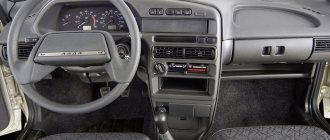
The combination of devices of Lada Granta and Lada Kalina 2nd generation is designed to display driving characteristics, the current state of vehicle systems that ensure traffic safety, as well as the correct operation of the entire vehicle as a whole. Next, we will consider a description of the Lada Granta dashboard, as well as the meaning of instruments and alarms.
Description of the Lada Granta/Kalina 2 panel:
- tachometer , shows the speed of the engine crankshaft, the red scale zone indicates a dangerous operating mode for the engine;
- engine management system malfunction indicator (Check Engine) , turns on orange when the ignition is turned on and goes out after the engine starts, the lamp is lit after starting the engine or while driving indicates the failure of any element of the engine management system (does not mean that the engine should be stopped immediately, however, the cause should be eliminated as soon as possible), the error can be determined using the diagnostic connector;
- left turn signal indicator;
- emergency low oil pressure indicator , turns on in red when the ignition is turned on and goes out after starting the engine, the lamp is lit when the engine is running and a constant (for 5 s) buzzer signal indicates insufficient oil pressure in the system;
- ABS anti-lock braking system status indicator (optional) turns on orange when the ignition is turned on and after 2 seconds. after the engine starts, it goes out; in other cases, the lamp is lit, indicating a system malfunction that should be repaired at a specialized service station;
- immobilizer mode indicator lights up orange and displays the status of the immobilizer and the vehicle security mode;
- The coolant overheat indicator turns on in red when the ignition is turned on and after 5 seconds. after starting the engine it goes out, the sound signal indicates engine overheating (t>115C), the signal will be repeated until the temperature drops below 110C, when the indicator turns on, it is prohibited to operate the car, otherwise it will lead to serious engine damage;
- brake system emergency indicator , turns on red when the ignition is turned on and goes out after the engine is started, the lamp is lit and the buzzer signal (5 lights on) when the engine is running indicates a drop in the brake fluid level below the “MIN” mark in the master cylinder reservoir, operate the car with the light on indicator is prohibited;
- indicator for turning on the right turn signal (with a green filter in the form of an arrow);
- battery charging indicator , turns on in red when the ignition is turned on and goes out after the engine starts, the lamp is lit or glows half-lit while the engine is running indicates a lack of charging current due to a malfunction of the generator or voltage regulator, as well as low voltage (or breakage) of the belt generator drive, operating the vehicle with the indicator on is prohibited;
- speedometer , shows how fast the car is currently moving;
- indicator of the operating mode of the exchange rate stability system (ESC) (in a variant version), turns on yellow when the ignition is turned on and goes out after starting the engine, the lighting of the “ESC OFF” lamp indicates that the system is turned off, and lighting and flashing while driving indicates the activation of the exchange rate control system stability, in other cases the burning of the lamp indicates a system malfunction;
- signaling device prohibiting transition to higher gear “O/D OFF” (not used);
- headlight high beam indicator , indicates that the headlights are on high beam;
- signaling device for turning on the rear fog lights , indicates that the ZPTF is turned on;
- low beam headlight indicator , indicates that the headlights are low beam;
- indicator for turning on the front fog lights , indicates that the PTF is turned on;
- daily mileage counter reset button , by pressing the button, set the daily mileage counter in the liquid crystal display to 0 or select the daily or total mileage display modes;
- liquid crystal display of the on-board computer , displays information from the BC, see description below;
- door open indicator , lights up red if the door is open;
- reserve fuel indicator indicates the need to refuel the vehicle; do not allow the gasoline to run out completely, as this may damage the fuel pump;
- low tire pressure indicator , lights up when tire pressure drops;
- the electric power steering status indicator (connected in a variant), turns on in orange when the ignition is turned on and goes out after the engine is started; the lamp is lit while the engine is running indicates a malfunction of the power steering, which must be eliminated as soon as possible;
- driver's seat belt warning light , lights up when the ignition is turned on if the seat belt is not fastened;
- power unit fault indicator (not used);
- Airbag status indicator turns on in orange when the ignition is turned on and goes out after the engine starts; in other cases, the lamp is lit indicating a system malfunction; you must contact service as soon as possible, because In addition to failure in an emergency, the airbag may unexpectedly inflate.
Sound insulation of Kalina panel/dashboard
| The disease of Russian cars is rattling, crickets and squeaks, and the LADA Kalina panel is no exception; it is also made of inexpensive plastic, like the rest of the interior elements. Let's figure out how to soundproof Kalina's instrument panel without removing or dismantling it. |
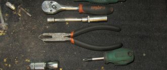
If you decide to make soundproofing for Kalina yourself, then you will have to buy:
- Anti-creak (modelin).
- Vibrating material (for example, STP).
- Plastic clamps.
- Hot-melt gun and hot glue.
- Bitoplast or splen, optional.
Instrument panel Kalina, sound insulation without removal
There is no need to remove the dashboard assembly, but you will have to remove the attached elements. As a result, you should see something like this:
About the main panel instruments
We offer you a description of the panel icons.
- Topping the “list” is the tachometer. This is the most important device that the dashboard contains, especially in sports cars. Its scale displays the number of revolutions of the Lada Kalina engine in a specific unit of time (per minute).
- Now about the speedometer. This component allows the owner to control the speed of movement. Traditionally, for domestic cars the scale is graduated in kilometers per hour.
- Fuel sensor. This analyzer shows the fuel level in the tank. When the arrow of the device enters the red zone, this indicates a minimum level. It is strictly not recommended to travel with such a supply of fuel, since air pockets in the line will damage the pump if it gets into the pump. If the instrument panel signals with an orange light, this indicates that the emergency fuel reserve of 5 liters has been included in the consumption, after the combustion of which the engine will stop naturally.
- Coolant temperature sensor in the engine cooling circuit. The arrow reading of this device must be monitored continuously. If disturbances occur in the system, the needle “vigorously creeps” into the red zone, terrifying the owner due to the risk of engine overheating. With this development of the situation, the temperature of the antifreeze reaches 115 degrees (Celsius). The movement cannot be continued.
- Fuel level warning device. This component produces an audible signal indicating the need to replenish the fuel tank.
- Direction indicators. Indicators in the form of arrows are directed to the right and left sides. The symbols flash green, accompanied by relay clicks.
- Reset daily mileage. The button located next to the odometer is responsible for its activation.
- Emergency Signal. In active mode, the button with the symbol present on it blinks vigorously, spreading a red glow around it. With her in the ensemble, the external marker lights blink. This mode should be turned on in emergency situations or other situations that put the driver at a dead end (got lost, got a call from an angry boss, etc.).
- Electric amplifier indicator. This orange symbol goes out more slowly the more the wheels are turned when the engine is started.
- High beam symbol. The lamp turns bright blue when the corresponding light mode is activated by the driver.
- Parking brake Lada Kalina. If you cock the handbrake, this lamp will light up red.
- Oil pressure. This symbol lights up red when the ignition is turned on and goes out 3-4 seconds after starting the engine. If it continues to glow, then the engine needs to be diagnosed (first the oil system, and then all other components).
- Dimensions. The green indicator lights up when the external side lighting is turned on.
- Airbag symbol. The orange lamp lights up when the ignition is turned on and immediately goes out when the engine starts.
- Immobilizer. This is also an orange indicator showing the status of this node in arming mode.
- On-board controller monitor on liquid crystals. The top line is occupied by the daily mileage indication. At the very bottom of the screen, an indication of the outside temperature, a timer and an indication of the average fuel consumption of the Lada Kalina car are displayed.
- Seat belt symbol. Those who do not fasten their seat belts will immediately be “caught” by a red indicator, which will “treacherously” light up as soon as the vehicle starts moving. In addition, the driver's ears will be shocked by an intermittent beep.
- Battery indicator. Illuminates when the ignition is activated and goes out when the engine starts. The color of the signal lamp is red.
- Symbol for minimum fluid in the brake system. Its signaling algorithm is similar to the action just indicated (for the battery).
- Brake force distributor. The indicator also lights up when the ignition system is turned on and is deactivated when the power plant starts.
- Wear of brake pads. “Welcomes” the driver when the pads reach the minimum thickness.
- ABS symbol. Lights up when there is a breakdown of components of the brake blocking system. Similar to the previous symbols, it activates and goes out. Its color is also orange.
- Motor indicator. Turning on the ignition of the LADA Kalina causes this warning lamp to “flare up” in orange, and starting the engine turns it into an inactive state.
Perhaps this is a complete description of the icons.
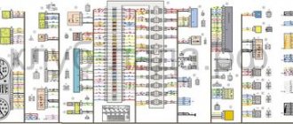
Electrical connection diagrams for the instrument panel of LADA KALINA 11174, 11184, 11194 cars
Electrical connection diagram for the instrument panel of LADA KALINA 11174, 11184, 1119 cars
4
Electrical connection diagram for the instrument panel of LADA KALINA 11174, 11184, 11194 cars.
(click to enlarge).
Dashboard diagram for LADA KALINA 11174, 11184, 11194 cars.
(click to enlarge).
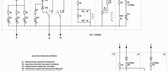
List of elements of the electrical connection diagram of the instrument panel wires of LADA KALINA 11174,11184,11194 cars
1,2,3,4 – blocks of the instrument panel wiring harness to the blocks of the rear wiring harness; 5,6 – blocks of the instrument panel wiring harness to the blocks of the front wiring harness; 7 – block of the instrument panel wiring harness to the block of the wiring harness 8 – block of the instrument panel wiring harness to the block of the front wiring harness; 9 – lighting control module; 10 – ignition switch; 11 – on-board computer mode switch; 12 – windshield wiper switch; 13 – sound signal switch; 14 – light signaling switch; 15 – instrument cluster; 16 – evaporator temperature sensor; 17 – interior air temperature sensor; 18 – air conditioner switch; 19 – controller of the automatic climate control system; 20 – heater damper gearmotor; 21 – rear window heating switch; 22 – alarm switch; 23 – brake signal switch; 24 – cigarette lighter; 25 – electric amplifier control unit; 26,27 – blocks of the instrument panel wiring harness to the radio; 28 – backlight lamp for the heater control panel; 29 – illuminator; 30 – mounting block: 31 – heater electric motor switch; 32 – heater electric motor; 33 – additional resistance of the heater electric motor; 34 – glove box lighting; 35 – glove box lighting switch; 36 – control unit of the APS-6 automobile anti-theft system; 37 – driver airbag module; 38 – passenger airbag module; 39,40 – blocks of the instrument panel wiring harness to the blocks of the ignition system wiring harness.
KZ – additional starter relay; K4 – additional relay; K5 – relay-interrupter for direction indicators and hazard warning lights; K6 – windshield wiper relay; K7 – headlight high beam relay; K8 – sound signal relay; K9 – relay for turning on fog lights; K10 – relay for turning on the heated rear window; K11 – electric seat heating relay; K12 – air conditioner compressor clutch activation relay;
Instrument panel wiring harness – 11186-3724030-20.
added 12/30/10 09:49:55 | viewed 21957 times
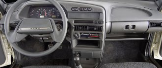
We dismantle the device ourselves
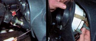
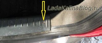
To remove the dashboard in Kalina-2, first dismantle the plastic cladding. The part is held in place by three self-tapping screws, two of which are immediately visible. Look at the tidy below and you will find them. The third screw, in turn, is located in the fuse compartment.
The fuse compartment will be covered with a cover.
In the figure, the required element is indicated by the number “3”.
In the absence of cladding, it is easy to find 4 screws holding the tidy in place. By unscrewing them, the block can be completely dismantled. But don’t rush: when dismantling, you will need to disconnect the connector. This means that even before performing all operations, the battery terminals are disconnected.
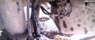
Usually only the negative terminal is disconnected. The part is held in place by one nut, and to unscrew it you need a 10mm wrench.
Electrical diagram of the rear wiring harness Kalina 2
1, 2 – rear wiring harness blocks to the instrument panel wiring harness blocks; 3 – right side direction indicator; 4 – left side direction indicator; 5 – hand brake sensor; 6 – rear wiring harness block to the tailgate wiring harness contacts; 7 – interior lighting unit; 8 – switch in the driver’s seat belt; 9 – trunk lighting; 10 – electric fuel pump module; 11 – right lamp; 12 – rear wiring harness block to the tailgate wiring harness contacts; 13 – left lamp; 14 – rear wiring harness block to rear left door wiring harness block; 15 – rear wiring harness block to rear right door wiring harness block; 16 – rear wiring harness block to the front right door wiring harness block; 17 – rear wiring harness block to the front left door wiring harness block; 18 – airbag control unit; 19 – rear wiring harness block to the front wiring harness block; 20 – block of the rear wiring harness to the block of the wiring harness of the parking system sensors; 21 – control unit and alarm unit of the safe parking system; 22 – parking system switch; 23 – speaker of the safe parking system; 24 – switch for interior lighting in the driver's door pillar; 25 – interior light switch in the right front door pillar; 26 – switch for the interior lighting in the pillar of the right rear door; 27 – interior light switch in the left rear door pillar; 28 – right seat electric heater switch; 29 – left seat electric heater switch; 30 – electric heater of the right seat; 31 – electric heater of the left seat; 32 – driver’s seat belt pretensioner; 33 – passenger seat belt pretensioner; 34 – central unit of body electronics; 35 – sensor for automatic glass cleaning system (rain sensor); 36 – rain sensor sensitivity regulator; 37 – rear wiring harness block to the instrument panel wiring harness block; 38 – right rear speed sensor; 39 – left rear speed sensor.
Adding a digital scale
For those who have experience working with plastic, the following tuning option is recommended.
In the instrument panel, under any of the two scales, you can cut out a window in which a standard indicator is fixed. We are talking about a digital indicator consisting of two or three separate segments.
The plane of the tidy is cut through, an indicator is attached to the window
When the modification is completed, the dashboard looks like this:
3-segment indicator installed and secured
If there are glares, use a simple solution: cover the inside of the glass with a matte tint film. Good luck.
Removing the instrument panel on Lada Kalina 1
The first step is to disconnect the battery from the power supply system. Disconnect the negative terminal from the battery. If the temperature in the cabin is below +15°C, it needs to be warmed up to +20°C. The dashboard of Lada Kalina 1 is well illuminated by a flashlight, but additional light sources can be used.
The procedure for dismantling the shield:
- The steering column is installed in the lowest position.
- Removing the instrument cluster trim, unscrew the 2 screws at the top.
- Pull the cover towards you, overcoming the efforts of the two lower clamps.
- Use a Phillips screwdriver to unscrew the 2 screws located on the sides of the instrument panel.
- Move the top part of the shield towards you, tilting it.
- Disconnect the connector with wires by turning the lock.
- Remove the instrument cluster from the recesses into which the structure's shafts are inserted.
Tip: the screws can fall behind the panel while unscrewing. It is recommended to use a screwdriver with a magnetic tip.
After this, the Lada Kalina 1 dashboard is repaired or replaced. You can replace the light bulbs by turning the desired socket counterclockwise.
The lighting devices are assembled with a socket, the power of each is 1.2 W. EEC designation W1,2W.
The procedure for removing the instrument panel on Lada Kalina 2
The dismantling steps for Lada Kalina 2 differ from the first model. The reason is that engineers increased the number of attachment points, which reduced the “rattling” effect after long-term use. Correct replacement of the dashboard is carried out in compliance with standard conditions: heated interior, lighting, disconnected battery.
How to remove the panel on Lada Kalina 2:
- Removing the protective plug located in the lower left part; it is secured with latches. In early models, it is necessary to unscrew the screws to completely remove the fuse box cover.
- Unscrew the 2 screws of the decorative trim and dismantle it.
- Remove 4 bolts on the dashboard (2 each on the bottom and side).
- Tilt the shield, disconnect the connector by turning the lock.
- Remove the panel.
To remove plastic parts, you can use a set of polymer pullers. It will also be needed to replace moldings, clips, and decorative overlays.
After dismantling, the on-board computer readings are reset to factory settings, with the exception of mileage. If the machine is used for personal purposes, you can reconfigure the system yourself. In company vehicles, it is recommended to record the data before starting work. They may be needed to check the condition of the machine.
conclusions
After reading the information given in the article, it will be easier for you to navigate behind the wheel and control the operation of the Lada Kalina car systems.
The instrument panel serves to inform the driver about all important processes occurring in his car. It is by using the scales, indicators, symbols and lamps located on this device that the person sitting behind the wheel is able to monitor the performance of components and systems. For the shield to function correctly as a single system, it requires regular diagnostics. It consists not only of scanning by connecting electronic reading devices to the computer, but also by visually monitoring the performance of all specified components of the dashboard (lamps, etc.).
So that the owner of the Lada Kalina, namely the instrument panel of this model we will talk about today, can easily navigate this complex device, the manufacturer kindly agreed to complete the car with the appropriate instructions. It is enough to familiarize yourself with its postulates and all the secrets of the dashboard will be revealed to you, then the instrument panel will not seem like something incredibly complicated.
The manufacturer did his best when developing the design of such a thing as the instrument panel on the Lada Kalina car. It is unlikely that you will be able to find owners dissatisfied with the “interface” of the device. The dashboard is painfully informative and primitive in terms of perceiving symbols and managing some of them.
Now let's move on to a more detailed consideration of the structural components of such an important element of the car as the dashboard. Many car owners will find a full description of the icons useful.
Replacing LEDs
Having disassembled the instrument panel unit, you will notice that the illumination of two scales and the display is provided by flat LEDs. They, in turn, can be replaced with parts of the same standard size. But remember one rule: the switching polarity cannot be violated. On a planar diode, polarity is indicated by the presence of a “bevel” on one side.
There is an example when standard elements were replaced with blue light diodes:
Blue backlight of the display and two scales
Blue backlight of the standard display
The next video will show how you can further improve the tidy by simply replacing the LEDs.
The operating voltage of one diode is 3-3.5 Volts. Do not install elements designed for other voltages. It is not recommended to use LEDs that are too powerful and consume significant current.
Which wire goes where?
First, let's look at the back of the instrument panel. At the top there are:
- fuel level indicator;
- dashboard lighting lamps;
- control of right and left turns (separately);
- tachometer;
- block with many plugs;
- coolant temperature gauge.
As you can see, there is really nothing particularly complicated here. At the bottom of the instrument panel on the back side there are controllers:
- high beam;
- "emergency lights";
- CHECK ENGINE;
- battery charge;
- parking brake;
- oil pressure;
- air damper (for models with a carburetor);
- outdoor lighting work.
In addition, there is also a speedometer and a brake fluid level indicator lamp.
Now let's take a closer look at the pads. There are two of them - white and red. In the first, the connectors and wires look like this (in order):
- Ground wire black.
- Red-brown – low-voltage supply from the ECU to the tachometer.
- Yellow – high-voltage supply to the tachometer from the coil.
- Red-blue - comes from the battery through the 6th fuse Const with a voltage of 12 volts.
- Green-white - leads to the coolant temperature sensor.
- Green-yellow – fuse F1, responsible for the side lights.
- This connector has no color, it goes to the throttle valve.
- Red and white – leading to the CHECK ENGINE indicator light.
- 2 orange wires leading to two F19 + 12 volt power fuses.
- Same as the previous connector.
- 2 blue-brown wires leading to the “VK” terminal of the handbrake.
- The output to terminal D of the generator is a brown-white wire.
- Gray and blue - wire going to the oil pressure sensor.
In the red block, the connector number according to the account, the color of the wires and the devices to which they lead are as follows:
- Red-blue – leads to the external temperature sensor.
- Orange – goes to power fuse F19 + 12 volts.
- 2 black ground wires.
- White – leads to the instrument lighting switch.
- Blue – to the right turn indicator.
- Blue-black - to the left turn indicator.
- Blue-pink - to the brake fluid level sensor.
- Brown – leads to the on-board computer.
- Gray - to the speedometer.
- Pink – to the fuel level indicator.
- 2 green-black wires leading to fuse F3, which is responsible for the high beam.
- Blue-white - to the hazard warning switch.
- The white wire leads to terminal 50 - the ignition switch.
It is worth especially noting here that the most typical and common pinout diagram is shown above. However, different manufacturers may have differences in color markings. For example, in the instrument panel manufactured by the Kursk "Schetmash" there will be minor differences from the above diagram, in particular in the red block (connector number and wire color):
- black;
- red-brown;
- yellow;
- red and white;
- green-white;
- 2 brown wires;
- empty;
- red and white;
- blue;
- orange;
- blue-brown;
- white-brown;
- blue-gray.
As you can see, there are still certain differences, even if they are small. However, these little things are very important. Therefore, it is best, before starting work, to find out which panel your car has (by year of manufacture and manufacturer), and then find the correct pinout diagram. However, there is another option - the self-adhesive pieces of paper already mentioned above. When disconnecting the wires, be sure to label them - this will greatly facilitate the assembly process.
Rear door wiring harness diagram Kalina 2
1 – contacts of the tailgate wiring harness to the rear wiring harness block; 2 – block of the wiring harness of the rear additional (tailgate) to the block of the wiring harness of the license plate lights; 3 – gear motor for the electric drive of the tailgate lock; 4 – rear window heating element; 5 – rear window wiper gear motor; 6 – tailgate lock; 7 – contacts of the tailgate wiring harness to the rear wiring harness block 2; 8 – additional brake signal.
How the “non-ITELMA” dashboard works, video example
Using the instrument panel, the driver can monitor the vehicle’s condition, driving characteristics and other functions and processes that affect the safety of movement. Also, with the help of indicators, the car owner will be able to operate it correctly. Next, a description of the indicators on the instrument panel will be given to make it easier for a novice driver to understand.
Diagram, instrument panel pinout
By the way, do you know how to apply these schemes in action?
All other schemes are suitable for Kalina 2 hatchback.
Electrical diagram of the car: 1 - right headlight; 2 — hood open sensor; 3 — sound signal; 4 - starter; 5 - battery; 6 - generator; 7 — windshield wiper gear motor; 8 — left headlight; 9 — right front door power window switch; 10 — motor-reducer for window lifter of the right front door; 11 — connection blocks to the right front speaker; 12 — electric drive for locking the lock of the right front door; 13 — windshield washer electric motor; 14 — ambient temperature sensor; 15 — block for connecting the wiring harness of the engine control system; 16 — electric drive for locking the left front door lock; 17 — brake fluid level sensor; 18 — connection blocks to the left front speaker; 19 — power window switch for the right front door, located on the driver’s door; 20 — left front door power window switch; 21 — door lock switch; 22 — motor-reducer for window lifter of the right front door; 23 — mounting block; 24 — control unit for the automobile anti-theft system; 25 — security alarm control unit; 26 — instrument cluster; 27 — right side turn signal; 28 — glove box lighting lamp; 29 — switch for the glove compartment lighting lamp; 30 — brake signal switch; 31 — ignition switch with transponder of the automobile anti-theft system; 32 — control unit for external lighting, instrument lighting and headlight beam direction control; 33 — steering column switch; 34 — left side direction indicator; 35 — connection blocks to the right rear speaker; 36 — electric drive for locking the right rear door; 37 — rear window heating switch; 38 — reverse lock switch; 39 — alarm switch; 40 — heater fan operating mode switch; 41 — additional resistor of the heater fan electric motor; 42 — heater fan electric motor; 43 — connection blocks to the left rear speaker; 44 — electric drive for locking the left rear door; 45 — electric fuel pump with fuel level indicator sensor; 46 — reverse light switch; 47 — parking brake warning switch; 48 — cigarette lighter; 49 — reverse lock solenoid; 50 — connection blocks to the head unit of the sound reproduction system; 51 — backlight lamps for the ventilation and heating system control unit; 52 — electric power steering control unit; 53 — interior lamp; 54 — right rear light; 55 — electric drive for locking the trunk lock; 56 — trunk light switch, built into the trunk lid lock; 57 — license plate lights; 58 - additional brake signal; 59 — rear window heating element; 60 — trunk light; 61 - left rear light. This diagram does not show the connection points and wiring harness terminals.
Electrical diagram of the front wiring harness Kalina 2
1 – right headlight; 2 – electric motor for washers; 3 – left headlight; 4 – starter; 5 – rechargeable battery; 6 – main fuse block; 7 – generator; 8 – sound signal; 9, 10, 11 – front wiring harness blocks to the instrument panel wiring harness blocks; 12 – air conditioning fan electric motor; 13 – electric fan of the engine cooling system; 14 – ABS hydraulic unit; 15 – right front speed sensor; 16 – left front speed sensor; 17 – front wiring harness block to rear wiring harness block; 18 – right fog lamp; 19 – left fog lamp; 20 – ambient temperature sensor; 21 – automatic transmission control controller; 22 – air conditioning compressor; 23 – audible alarm signal; 24 – rear window washer electric motor; 25 – automatic gearbox; 26 – block for automatic gearbox; 27 – block to the automatic transmission selector switch; 28 – block to the automatic transmission speed sensor.
Rework by replacement
This option seems obvious: the speedometer and tachometer can be left in place, and the computer display can be replaced. In reality, such a replacement is difficult to perform. The on-board computer in Kalina-2 is integrated into the tidy circuit, so you cannot get rid of it. The instrument cluster unit is usually replaced as an assembly, and third-party companies have been able to provide several suitable solutions.
Tidying with a computer from a third-party company (option 1)
Tidying with a computer from a third-party company (option 2)
Tidying up the updated Priora, ITELMA
You can install a more “complicated” dashboard than in Kalina, produced by ITELMA. This company is a supplier of electronics for all VAZ cars. We will leave the choice to the owner. Happy tuning!
Installation of the dashboard Kalina 1
Installation is done in reverse order. For prevention, all surfaces are cleaned of dust and dirt, checked for defects and damage. The rag is dry; moisture may get on the surface of the electrical connector. Before installing a new instrument panel, check the correct location of the fastening units.
Installation steps:
- Install the plug connecting to the car's electrical network.
- Turn on the battery and check the operation of the dashboard.
- Disconnect the battery.
- Insert the lower rollers into the mounting recesses.
- Fix the shield, tighten 2 screws.
- Install the cover plate into the lower latches and screw in the mounting screws.
Several types of instrument panels have been developed for the Lada Kalina. They differ in appearance and functionality, but their installation diagram is the same.
When connecting the plug, you need to carefully move the latch to the “closed” position. This part is made of thin plastic and may break if pressed hard. First, insert the plug tightly, then turn the latch.
VAZ-2110 dashboard: pinout
Probably, hardly anyone will argue with the fact that the VAZ “ten” is not the pinnacle of design thought.
However, there is nothing surprising here, because this car was designed back in the last century. At the same time, the compensator, and quite a serious one, in this case is the price. In other words, a certain compromise is proposed - the imperfection of the car in exchange for an acceptable cost. Well, the choice is ultimately made by the car owner himself, deciding whether this option is suitable for him. You can talk about the advantages and disadvantages of this model for quite a long time. However, this is not what we will talk about now. Those who decide that the “ten” is a suitable option in terms of the ratio between price and quality often want to somewhat refine their iron horse during operation, making changes to both the exterior and the interior.
If we talk about tuning the car interior, then one of the main objects of improvement here is the dashboard. Many people simply don’t like the native version, which, frankly, doesn’t look very attractive. Yes, after the “Zhiguli” this is an undoubted step forward, but it’s already the 21st century outside the window, and I want something more beautiful and pleasing to the eye.