Thanks to system diagnostics, you can quickly find out which sensors are failing. The computer sends a signal to them and then deciphers the return pulse. The received code indicates the place where the sensor responded to the request incorrectly. Let's look at what faults self-diagnosis will help you find on a VAZ-2115 car.
How to do a self-diagnosis
If a fault check is done at a service station, a special device is connected to the on-board computer, which displays errors in a four-digit format. However, domestic manufacturers have provided another way to obtain information about the condition of the car - to do this, it is enough to run self-diagnosis. It’s easy to do it yourself if you follow the following instructions:
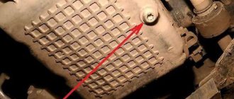
- Below the speedometer on the dashboard there is a dedicated odometer button.
- Press it and turn the ignition key to the first position.
- Immediately after turning the ignition key, release the button.
- After these actions, the instrument needles should begin to move.
- Press the button again and release immediately. If you did everything correctly, data about the firmware version of the on-board computer will appear on the speedometer.
- Press the button one last time and release it. After this action, fault codes should appear on the display.
Determining the fault yourself
Of course, we, like real drivers, always strive to solve any problem with our own hands. Well, you don’t like it when someone else’s guy treats your “swallow” and I understand you perfectly. However, if we consider the issue of the on-board computer, then everything is somewhat different, but in certain cases you can handle it yourself. I warn you right away: do not listen to pessimists who will foam at the lips to prove that you cannot defeat computer errors. But remember once and for all, the error codes will differ from the service station options, since by and large we will be testing the dashboard without resorting to the help of that same “on-board driver”. Instead of a number with a four-digit value, we will be presented with a two-digit one.
Before I tell you about the different combinations, follow a few simple steps. They will help not only determine the firmware version, but also find out about existing faults. Self-diagnosis begins with these actions!
- Find the odometer button and hold it down.
- Turn the key to position 1.
- Release the odometer (the arrows will start moving).
- Press the odometer again and immediately release (information about the firmware will appear).
- Repeat the previous steps again, after which, if there are any obvious faults, you will see their error codes.
If the Check Engine light is on, this means a failure in the electronics system, then you cannot do without specialists. In other cases, after carrying out these actions using the following information, it will be possible to read errors. Combinations that may appear on the instrument panel:
- 1 – failure of the microprocessor;
- 2 – fuel level sensor is faulty;
- 4 – increased voltage in the electrical circuit;
- 8 – low voltage in the electrical circuit;
- 13 – there is no signal from the oxygen indicator;
- 14 – increased coolant temperature;
- 15 – reduced coolant temperature;
- 17 – low voltage on-board network;
- 19 – malfunction of the sensor that determines the position of the crankshaft;
- 24 – speed sensor has failed;
- 41 – phase sensor error;
- 51 – permanent storage device, unstable;
- 53 – CO potentiometer is faulty;
- 61 – lambda probe does not work correctly.
Even after eliminating the malfunction, the corresponding codes will still appear on the error panel. “How to remove these readings?” you ask. Yes, very simple! Turn on the ignition and disconnect the positive terminal from the battery for a few seconds.
After which, we check the result, there is almost a 100% guarantee that if the error is corrected, the problems will disappear. Another nuance that can mislead you is the addition of errors. That is, if there are several of them, for example: 24 and 41, then you will see the number 65.
How to decipher codes
If you do not know what the data displayed on the display means, then it is pointless to independently check the functionality of the sensors. Therefore, it is important to know how to decipher combinations. The following numbers appear most frequently:
- If code 1 appears, then the fault lies in the microprocessor of the on-board unit itself. This error can be corrected by changing the computer software. It is important to use only official firmware, otherwise you will damage the entire electrical system of the car.
- If the malfunction is hidden in the incorrect operation of the fuel sensor, then 2 will appear on the display. The same number means problems with the electrical wiring, especially if it is displayed in addition to 8.
- When the voltage in the network is high, error 4 appears, and when voltage is low, error 8 appears. If you notice these data, then you need to check the generator and battery. VAZ-2115 owners most often encounter generator malfunctions. It will need to be repaired or completely replaced.
- Malfunctions in the operation of the control lamp in the diagnostic circuit are displayed on the display in the form of a combination - 12.
- Failure of the oxygen level sensor is displayed as error 13. Check the filters, most often they are the cause of this combination. Combinations 33 and 34 indicate mass air flow. In this case, you may need to replace the sensor itself. A malfunction of the controller itself is indicated by code 61 displayed on the display. Experts recommend that if one of these combinations occurs, a full check of the functionality of the vehicle components is carried out. Start with the electrical wiring.
- Car enthusiasts often encounter combinations 14 and 15, which may appear along with an indicator indicating the need to add antifreeze. It is important to interpret this malfunction correctly - the appearance of this data on the display means that the temperature in the system is increased or decreased. The reason for this may be a malfunction of the thermostat. If the node is not damaged, then the problem most likely lies in the control unit.
- Combinations 16 and 17 are output when the voltage in the on-board network is insufficient or too high. It is necessary to check all wiring for short circuits and breaks.
- Code 19 occurs if the crankshaft position sensor does not respond correctly to the test. In this case, it is necessary to check the vehicle with an external device. If it shows a combination in the range from P0340 to P0343, then the breakdown may be hidden in the controller itself.
- With error 24, the on-board computer stopped receiving data about the vehicle speed.
Troubleshooting
Having figured out how the error is formed, what provokes it and on what cars it can occur, you need to answer the main question. It concerns how exactly to get rid of the error.
Experts give several recommendations in this regard.
- Using diagnostic equipment in the form of a scanner, check the ECU in deep diagnostic mode. This will open all errors that are in memory. If there are other errors than the one in question, they should be corrected by identifying the causes and then reset. After this, another diagnosis is carried out. It is possible that 0133 was the result of other malfunctions.
- If we are talking about the obvious presence of error P0133 and the reset did not give anything, then you will have to check the condition of the oxygen sensor and the associated components.
- First of all, it is recommended to check the current condition of the catalyst. Make sure there is no internal or external damage. If the integrity of the catalyst is compromised, a new one will need to be installed.
- Using diagnostic equipment, measure the voltage of the signal that comes from the oxygen sensor. This can be done with a regular multimeter set to voltage test mode. When the ignition is turned on, the reading should ideally be around 450 mV. If the ignition is turned off, wait for a reading of approximately 150 mV on the device. If they are different, the sensor needs to be replaced.
- A voltage of less than 150 mV when the engine is turned off supports the theory that the lambda probe is faulty. There is only one solution: replacing it.
- If the voltage is less than 150 mV under the same conditions, there are breaks in the wiring. You need to find them, carry out repairs, or better yet, replace the damaged wiring.
- When the car is equipped with gas equipment, to eliminate the error that appears, you will need to perform the correct settings and select the most suitable mixture. Quite often, it is because of problems with the gas rail that the error in question appears.
- Fuel injectors in the car should be cleaned and washed with special products. Their contamination negatively affects the air-fuel mixture, affects the behavior of the oxygen sensor, and the operation of the latter is ultimately disrupted. This entails the appearance of a corresponding error with code 0133.
- Be sure to check the exhaust system corrugation. Its integrity may be compromised. If the corrugation is burnt out, error P0133 will almost certainly appear until the fault is completely eliminated.
This is interesting: Clutch drives: what does it mean, why and what to do
To summarize, we can say the following. The appearance of error 0133 indicates that there are problems with the oxygen sensor. Its performance is impaired, the device reacts more slowly, which is why the ECU perceives this as an error in the engine’s operation.
The problem is quite common, but not critical. The main trouble is the change in dynamics and the increase in fuel consumption.
Diagnosing a malfunction is not difficult, nor is it difficult to fix it yourself. But sometimes the help of more qualified specialists may be required.
Errors that the injector may produce
Errors in the fuel injection unit and combinations associated with engine problems should be included in a separate group. During self-diagnosis, they may appear with the following signals:
- 35 – malfunction of the idle speed sensor, it will need to be replaced;
- 43 – incorrect signal from the detonation regulator, often appears when there is a break in the electrical circuit;
- 44 and 45 – problems with the injection system, fuel is excessively rich or, conversely, lean;
- 54 – the octane corrector controller does not respond;
- 55 – at high speeds the fuel mixture is lean.
It is worth considering combinations 44, 45 and 55 in more detail. If the malfunction is not hidden in the sensors themselves, then you can notice signs of it on the engine side:
- he will triple;
- Jerking may be felt when changing gears;
- in rare cases, the VAZ-2115 simply stalls for no reason.
If you notice one of these combinations on the display, then it is worth conducting a more thorough diagnosis of your car. In some cases, major repairs may be required. Those who are faced with the problems described should contact a service station, because often it will not be possible to repair the car on your own.
P0133 value
Modern cars are equipped with many sensors that send information depending on engine operating conditions to the ECU. These inputs are then processed by the controller to configure the various outputs to keep the motor running as efficiently as possible.
That's why modern vehicles are able to produce more power while using less fuel and meeting strict emissions regulations.
The DC is a very important input to the control unit as it senses the amount of oxygen in the exhaust stream and allows the ECU to adjust the air/fuel ratio to keep the engine running smoothly and efficiently.
The oxygen sensor associated with code P0133 is installed before the catalytic converter in bank 1. If the vehicle has 4 cylinders, there is usually only 1 bank. If you have a V-twin engine, then you need to find out where bank 1 is located.
A properly functioning upstream oxygen sensor should constantly switch between 0 and 1 volts. When the controller detects that the sensor is not switching quickly enough or is not responding promptly to various driving conditions, it stores a P0133 trouble code.
Incorrect data during self-diagnosis
According to reviews from experienced VAZ-2115 owners, the on-board computer on this model cannot be called perfect. They recommend not relying entirely on self-diagnosis, since the data obtained from it does not accurately indicate problems with transport nodes.
The self-diagnosis system is based on signal processing from common sensors. They are unable to convey the specific data needed to accurately identify the problem. There are imperfections in almost every node. Several controllers are located on the air system and the fuel injection mechanism. They can fail both in the event of a serious breakdown or in the event of a broken conductor.
Most often, VAZ-2115 owners have to deal with incorrect operation of the generator. It is this unit that often produces too low or high voltage, which causes malfunctions of all controllers.
Diagnosis and problem solving
The first step in the process of troubleshooting P0118 is to review the Technical Service Bulletins (TSBs). For known problems with a specific vehicle.
Perform a thorough visual inspection to check the wiring for obvious defects such as scratches, scuffs, exposed wires, or burn marks. Next, you should check the connectors and connections for safety, corrosion and damage to the contacts.
Be sure to carefully check the integrity of the wire harnesses and secure any loose wires. If you find a burnt wire, solder it and make sure it is properly insulated.
Checking the coolant and thermostat
Make sure the coolant level is correct, both in the radiator (when cold) and in the coolant overflow reservoir. Make sure there are no leaks and that the sealing cap is working properly.
If there is not enough coolant in the system, the engine may not warm up properly. Because if the temperature sensor is not in contact with the coolant, it will not read the temperature.
Using a non-contact thermometer or scan tool with real-time data streaming, check to see if the engine is warming up properly. Typically, the upper radiator hose should remain relatively cool until the thermostat opens. After which it will heat up quickly.
Using a thermometer or scan tool, check the engine temperature after 10-15 minutes of operation. If the temperature does not reach operating temperature, check the ECT sensor.
Checking the coolant temperature sensor (ECT)
Visually check the sensor for damage to the wiring or connector and repair if necessary. Then connect the OBD2 scanner, if the engine temperature is excessively high, about 140°C, it is not normal.
Disconnect the sensor on the engine and see if the readings drop by, for example, 10°C. If so, then the sensor is most likely faulty, shorted internally, causing a low resistance signal to be sent to the PCM.
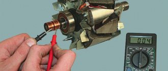
But, if you want to be completely sure that it is the sensor and not the wiring, you can run a test. Check the sensor's resistance to ground using an ohmmeter. The resistance of a normal sensor will vary slightly depending on the vehicle.
But basically, if the motor temperature is around 95 degrees Celsius, then the resistance will be around 200 ohms. At a temperature of about -20°C, the resistance will be more than 10,000 Ohms.
Removing the error from the device memory
This procedure is used in three cases:
- the occurrence of an error blocks the ability to operate the car (you need to get to the service station under your own power);
- a complete check of all components was carried out and no fault was found;
- The damaged part has been repaired or replaced.
To reset the on-board control system data, you must remove all terminals from the battery and then plug it back into the vehicle's power circuit. It will only take a few seconds to disconnect the battery. After this, the error record will be erased from the system memory. If you want to carry out this procedure for further operation of the vehicle, then remember that the trip should be short - to the nearest car service center.
Other indicators indicating breakdowns
The vehicle's instrument cluster contains indicator lights that warn of faulty systems. At the same time, the problem can be recorded by the controllers, the error code can be read during self-diagnosis or by a test device. Some of the faults displayed by the lamps do not prevent the vehicle from continuing to move. The location of the control indicators depends on the generation of the machine.
Color designations
Indicators are used to display faults:
- red (further operation of the vehicle is prohibited or undesirable);
- orange (movement into the repair area is allowed).
Troubleshooting
The red silhouette of a car with open doors indicates that they are not locked tightly. It's worth checking the trunk lid as well. The problem occurs if the sensors are damaged or shorted (the door locks are locked). To eliminate the error, close the covers tightly or make sure the limit switch is working properly. The orange airbag warning light should come on for a few seconds after the ignition is activated. A constant light on the indicator indicates problems with the airbags or the control unit.
The inclusion of red lamps for battery charging, emergency oil pressure, overheating, low brake fluid level or incorrect operation of the ABS hydraulic unit indicates the need to stop and turn off the power unit. Further operation of the machine is allowed after diagnostics are carried out and the reasons for the warning lights are determined (for example, a low oil pressure lamp may be triggered due to a sensor failure or pump failure).
The orange oil change indicator reminds the driver to perform maintenance. Further movement of the vehicle is allowed. A signaling device with a graphic pictogram (called a saw or a spiral by its owners) is used on cars with gasoline engines; the lamp can operate in 2 modes. When the red LED turns on, further movement and operation of the engine are prohibited (for example, cases of failure of the throttle unit with simultaneous recording of error U1123 have been noted).
Activation of the orange LED in the graph indicator indicates faulty electrical or electronic components that allow movement. The driver needs to slow down and get to the nearest car service center. On crossovers with diesel engines there is an indicator for water entering the fuel filter. When the LED turns on, the car is sent for service.
Installing a new adapter
Modern adapters elm 327 with the OBD-II program (puncture) are suitable for the VAZ 2110 . You can also install them yourself. First you need to purchase an elm 327 and a cable for it. You already know the location of the diagnostic connector. Be sure to study the instructions, which indicate the pinout of the block and the location of each connector.
Connection diagram for ELM327 to 12 PIN diagnostic block
The pad can be removed quite easily. Insert your own cable into each connector of the block, making sure that the pinout of the elm 327 complies with the manufacturer’s instructions. Check that each connector is connected correctly and each cable is in the correct place. After this, the block is installed in its place.
Connecting the diagnostic connector to the block
Fault detection programs for elm 327 can be downloaded on the Internet, many of them in a free version. Now your VAZ is ready to detect errors in various car systems, and you can always download error codes from us.
Connecting the diagnostic connector to the block Connecting the diagnostic connector to the block
Step-by-step instructions for diagnosing a VAZ-2110 with your own hands
To carry out computer diagnostics of a VAZ-2110 car, it is recommended to contact specialized car services that have all the necessary equipment at their disposal. However, this approach has several significant drawbacks. Firstly, the procedure for identifying faults in a service station can be quite expensive. Secondly, unscrupulous technicians have a bad habit of embellishing the results obtained and claiming faults that actually do not exist.
That is why in this article we will look at how to do computer diagnostics of a VAZ-2110 with your own hands, provide detailed step-by-step instructions and help you minimize costs.