After the next update, the Priora began installing a restyled dashboard in the car’s interior. A large display has become located in the center, which can display not only on-board computer information, but also navigation. We'll tell you how to change the old instrument cluster on a Priora or Kalina to a new instrument panel.
Life hack: dashboard of a Lada Priora car, everything you need to know
Priora has several panels, depending on the year of manufacture, plus non-standard ones made specifically for it.
Everyone knows how important it is to know the instantaneous status of instruments and machine parameters. The panel, also known as the control panel, on a Lada Priora car is, in fact, brief information about the condition of the car at the moment. It contains all the basic information, from movement speed to indicator readings on malfunctions of the main units and components of the machine. When something in it doesn’t work, it’s immediately alarming, because it’s current information. A description of all the icons and their meaning can be found below in the article. Technology is gradually developing, so the dashboard is becoming more and more technologically advanced. But since the Lada Priora is a low budget car, the panel on it is of the same quality. On the first devices, the backlight often does not light up, or is only half lit. Of course, this does not make the Priora look good. The instrument panel on the Priora car changed with the restyling of the 2nd Lada car. And Lux cars come with navigation. In fact, its basic functionality remains the same - all basic information is visible. Here you can monitor the operation of the engine, monitoring the speed, and understand that it is time to take the car for maintenance when one of the lights comes on. The price of a first (1) and second (2) generation part starts from 6,000 rubles and above. Tidying saves you from speeding, helps you refuel on time and prevent the Priora from boiling.
Why is a CAN bus still needed, and the principles of its operation?
A modern car has modern on-board electronics with a huge number of control and executive modules, these include all kinds of controllers, sensors, etc..., and for the exchange of information, reliable and fast data transfer was required for communication between devices.
The modern CAN bus provides a duplex system for the simultaneous reception and transmission of digital information, processing it in one unit, where the data transmission speed plays an important role. The implementation of the canbus is a twisted pair cable and has made it possible to significantly reduce the electromagnetic fields that arise during the operation of the generator and other important vehicle systems.
Typically, CAN bus wiring is orange, distinguished from each other by different colored stripes (CAN-Higt is black, and CAN-Low is orange-gray).
With the advent of the CAN bus and the beginning of its use, the circuit of automobile conductors was freed from a certain number of conductors, which provided communication between the control controller between the diagnostic connector, the engine, multimedia (navigation systems on Android OS), the vehicle security system, etc...., using the KWP 2000 protocol.
Vehicle control protocol using the KWP 2000 CAN bus
The data processing speed via the CAN bus can be up to 1 Mbit/s, and the processing speed of information between vital systems in the car, for example, the ABS braking safety system, the engine transmission is 500 kbit/s. In addition to the main systems, the car has an equipment system that includes airbags, multimedia for the car, control units in the car doors, etc.. can be 100 kbit/s.
When exchanging information between any control units and using a transceiver, the signals for receiving and transmitting information are amplified to the required level.
CAN bus topology and waveforms
Each block connected to the CAN bus has a certain input resistance, as a result of which a CAN module load is formed. The load on the central CAN bus depends on the simultaneous connection and use of actuators and electronic control units of the vehicle and various sensors, for example - the resistance of the power unit connected to the CAN bus is on average 68 Ohms, information and command systems “COMFORT equipment” from 2.0 up to 3.5 kOhm. When the entire system is de-energized, the load resistance of the modules operating via the CAN bus is also turned off.
Fragment of a CAN bus with load distribution in the wires: CAN High CAN Low.
System, automotive control units, in addition to various load resistances, also have a data transfer rate, which can lead to an obstacle when processing different types of impulses.
To solve the technical problem of pulses of different characteristics, a gateway converter is used for communication between buses.
The converter is the so-called gateway interface, in a car it is used in the control unit or as a separate unit, etc... The converter interface is used for various input / output of information from the OBD diagnostic connector, via a specific wire connected to the diagnostic connector and connecting the central control unit with the OBD connector via CAN bus.
OBD is a unified diagnostic connector with a lot of conveniences and advantages for scanning a car for errors and diagnostics.
Block diagram of the gateway CAN interface.
As shown in the picture, communication in the car of the CAN bus electronic blocks occurs using different blocks, but doing one thing, the CAN bus power unit, the information command system and the Comfort system, depending on the brand of the car and their composition, the blocks may differ , but the essence of the idea remains unchanged.
Diagnosis of a vehicle for faults is carried out by connecting specialized diagnostic equipment with the necessary software, the so-called CAN bus analyzer, or using an oscilloscope (with a CHN bus analyzer) and a multimeter (digital).
Checking for CAN bus operation begins with measuring the resistance between the CAN wires. But it is necessary to remember that the CAN block of the information and command system bus and the COMFORT system are constantly under voltage, which cannot be said about the power unit. To do this, it is recommended to disconnect the battery at the time of checking; you can get by with one of the 2 terminals (plus or minus).
Basically, all CAN bus malfunctions consist of a break or short circuit of lines, load resistors, a violation of the operating logic, or a decrease in the signal level. In the case of a logic violation, searching and detecting the problem can only be done using a CAN bus analyzer.
Standard instrument panel - article number and price
The original car tidy exists in three types.
- the first is an option for a pre-restyling car;
- the second panel is for a restyled car;
- and the third is the “Lux” option for the restyled one, which has become faintly similar to all previous torpedoes.
Each of them contains standard elements such as a tachometer, so their functionality does not decrease. . Who wants to do tuning of the instrument panel, this option is for them.
Priora first generation
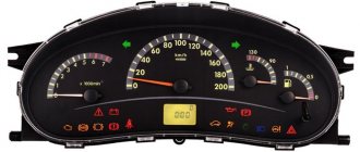
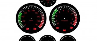
The instrument cluster for the first generation Lada Priora received catalog number 2170-3801010. Cost – about 6,000 rubles. Everything is standard with it - from left to right there are four arc scales with red arrows: odometer, speedometer, coolant temperature, fuel level. Below the speedometer there is a small on-board computer display, and above the arches are all the indicators, including the direction indicators.
Priora 2
For the Priora “Lux” variation there are two more “subtypes” - with or without a CAN bus. Different subtypes were made so that the panel could be connected to any car. Catalog number – 2170-3801010-50 without tire, 2170-3801010-60 with tire. It is distinctive in that it contains an elongated display with a screen that can highlight the navigator.
The catalog number of the combination for the “Norma” assembly is 21720-03801010-20. Cost – 6,500 rubles. Like the “Lux” version, it received a brighter speedometer and odometer, and the coolant temperature along with the fuel level indicator is hidden at the bottom of the speedometer and odometer. The base will not create a route on the display, but will show all the information in color.
The ignition key can be in one of three positions
0 – “off”; I – “ignition”; II – “starter” In the lock position “0” – “off” the power circuits are energized: side light; lighting of the interior, glove compartment and trunk; brake signals; sound signal; central lock; hazard warning lights. The key can only be inserted and removed from the ignition switch in the lock position “0”. When the ignition key is removed, the anti-theft locking mechanism may be activated, blocking the steering shaft. To lock the steering shaft, turn the steering wheel left or right until the locking element clicks. To unlock the shaft, insert the key into the ignition lock and, slightly rocking the steering wheel left and right, turn the key to position “I” - “ignition”. When the key is in position “I”, along with the above consumers, the power circuits are energized: elements of the engine control system; instrument clusters; headlights; direction indicators; fog light and reversing light in the rear lights; windshield wiper and washer; heater; electric door windows, heated rear window elements, electric drives and heated exterior rear-view mirrors. In the lock position “II” – “starter”, the starter is turned on. The key position is not fixed. Immediately after starting the engine, release the ignition key and it automatically returns to position “I”. If the first attempt fails to start the engine, turn off the ignition and, after waiting about 30 seconds, try to start the engine again. Hold the key in position “II” for more than 10 is not recommended, since this can lead to overheating of the starter motor and its failure. The ignition switch is designed to block an attempt to start an already running engine, which does not allow turning the key a second time from position “I” to position “II”, bypassing the “0” position. If the driver’s door is opened when the ignition is turned off and the key is left in the ignition switch, the buzzer emits a continuous sound trill, warning about the key being left in the ignition switch. If the key is removed from the ignition switch, but the side light remains on, then when When the driver's door is opened, the buzzer emits two intermittent beeps, warning that the exterior lighting has been left on.
Icons on the factory dashboard
All indicators should light up like a Christmas tree for three seconds when the engine starts. If some icon remains, it means the system is signaling a breakdown. To make it easier to understand all the indicators, here is a schematic picture:
1,5,9,10 are already known scales that display the main parameters that can change. 19 – on-board computer display. Further:
- 2 – Icon indicating the operation of the braking system.
- 3 – Battery condition. If the light remains on, the battery is discharged or the charge level is too low.
- 4.7 – Doublers for direction indicators (“turn signals”).
- 6 – Oil level (indicates low level).
- 8 – Handbrake. Lights yellow when the lever is tightened.
- 11 – “Gasoline light bulb.” Lights up when there are only 10 liters left.
- 12 – Button for switching on-board computer modes.
- 13 – “Emergency”.
- 14 – Electric power steering (indicates a breakdown).
- 15 – High beam on.
- 16 – Side lights/low beam.
- 17 – Airbag condition (malfunction).
- 18 – Immobilizer (if you hear a beep and the icon itself blinks, the immobilizer is faulty).
- 20 – Seat belts not fastened.
- 21 – Unsatisfactory condition of the service brake system.
- 22 – Disabling the airbag.
- 23 – ABS malfunction.
- 24 – “Check”, “Check Engine” - engine failure.
The exclamation mark is on - what to do?
We have noticed that new topics often appear on car forums where drivers ask about the exclamation marks that are displayed on the Lada Priora panel. They rarely specify where it is lit and what is depicted on the icon. In this section we have collected a small FAQ Below are all the exclamation marks that can light up on the instrument panel of a VAZ 2170 car. The designations of these icons are as follows:
- The red exclamation mark in the circle (bottom) is lit. The indicator indicates that there is a problem with the vehicle's brake system. This is usually a low brake fluid level. Add it to the tank and, most likely, the sign will stop lighting. If this does not happen, then it is worth checking the system for damaged components. When igniting, the indicator lights up for 4 seconds and then goes off.
- The red exclamation mark in the triangle/circle (above) is lit. Modern versions use a triangle instead of a circle. The indicator tells us about defects in the operation of the brake force distributor. Use extreme caution if the light comes on while driving.
- Exclamation mark next to the steering wheel icon. When illuminated for a long time, it indicates a malfunction in the electric power steering (EPS). Like other icons, it lights up when ignited and goes out after a few seconds if the system is working properly.
Sometimes the indication is caused by faults in the electronics. Terminals are coming off, contacts are oxidized, defects in the on-board computer are a few reasons for the random appearance of icons. To avoid damaging one of the systems, check the electronics first. To do this, it is enough to dismantle the device on the Lada Priora and see if the terminals are securely seated in the sockets. If the brake system indicator lights up, first check the fluid level in the reservoir, and only then fill in new antifreeze.
Possible faults
The instrument cluster does not always tell the truth, and sometimes its readings can mislead the driver - they may seem absurd. For each common malfunction, a brief commentary will be given on the possibility of eliminating them:
- The fault lamp does not light up (check the lamp);
- the lamp is on - check the sensor, reset the error via the diagnostic connector.
If none of the above measures help resolve the problem, carefully inspect the wiring - damage to it may cause the light bulb to activate or deactivate.
Pinout of the instrument panel of a Priora car
The panel pinout looks quite complicated, but there is a more simplified diagram that will help you figure out the wires connected inside:
- EUR
- "emergency light"
- Engine oil
- Handbrake
- Immobilizer
- Airbags
- Headlights and dimensions
- Right turn signal
- Left turn signal
- Electronic control unit
- Pad wear sensor
- Seat belts (closing sensor)
- ABS
- Reset button
- Brake system, brake fluid
- ABS
- High beam headlights
- Torpedo shield lighting
- "Weight"
- Thirtieth terminal
- Fifteenth terminal
- Fuel consumption
- Forward key
- Back key
- Ambient temperature sensor (minus)
- Ambient temperature sensor (plus)
- Fuel level
- Speed sensors
- Coolant temperature
- Odometer
- Diagnostics of the shield (service)
- Generator regulator
How to enable self-diagnosis of the instrument panel
Using the panel you can “dig into the brains” of the Priora:
- Hold the button under the fuel gauge and turn on the ignition. The display should indicate the start of the test.
- Press the button again. The display should show the operating system version.
- Click again. The system should show error codes:
- (2) – High voltage level;
- (3) – DT malfunction;
- (4) – DTOZH malfunction;
- (5) – DTV malfunction;
- (6) – Motor overheating;
- (7) – Low oil level;
- (8) – Malfunction of the brake system;
- (9) – Battery discharge;
- E – Brain error, EEPROM.
- If necessary, reset the error: hold the button for three seconds.
- Release the button. Click again. All indicators should light up.
- Leave all the buttons. After 30 seconds, the self-test will automatically complete.
Required
The Itelma instrument panel with navigation can be of two types (externally they are no different):
- 2170-3801010-50 without CAN bus;
- 2170-3801010-60 from CAN bus.
They are not interchangeable, so before purchasing, you should determine whether your vehicle uses a CAN bus or not.
- until 06.2012, cars were produced without a CAN bus;
- remove the instrument cluster and look at the article number or at the block with wires (see pinout of connectors below).
For Kalina (VAZ 1117, 1118, 1119) - all cars without a CAN bus.
- Right steering column switch with joystick (catalog number: 1118-3709340-20);
- Antenna (for roof installation): 1118-7903074.
You can also buy ready-made kits (device + antenna + switch):
- for Lada Priora - 2170-3801010-55;
- for Lada Kalina 1 - 1118-3801010-55.
Installation
Replacing the old instrument panel without CAN with a dashboard with navigation without CAN (2170-3801010-50) is carried out without modifications. We remove the old panel and install a new one in its place, insert the connector with wires, connect the antenna (we fix it on the roof) and, if necessary, change the right steering column switch.
If the old instrument cluster without navigation, but with CAN, and instead of it it is planned to install a new dashboard with navigation with CAN (2170-3801010-60), then you need to rearrange contacts 10-11 to 28-29 (if after connecting it still does not work, change 28 and 29 places). See instrument cluster pinout.
After installing the new instrument panel, the mileage will be reset to zero.
Navigation in the instrument panel runs on Windows CE 6.0 along with Navitel software. It is possible to update the software and download navigation maps from a USB card via a special USB input. Operating the car will become much more pleasant, the only drawback is the high price.
Equipment:
- Combination of devices;
- Change in understeer;
- Antenna.
The kit includes a complete combination installation kit. There is no need to saw or drill anything; everything falls into place without modifications.
Software: Navitel 5.0
After the next update, Priors began installing a redesigned dashboard inside the car. They began to place a large display in the center, on which you can view not only information from the on-board computer, but also navigation. We will tell you how to change the old instrument cluster on a Priora or Kalina to a new instrument cluster.
Required
The Itelma instrument panel with navigation can be of two types (externally they are no different):
- 2170-3801010-50 without CAN bus;
- 2170-3801010-60 from CAN bus.
They are not interchangeable, so before purchasing, you should determine whether your vehicle uses a CAN bus or not.
- until 06.2012, cars were produced without a CAN bus;
- remove the instrument cluster and look at the article number or at the block with wires (see pinout of connectors below).
For Kalina (VAZ 1117, 1118, 1119) - all cars without a CAN bus.
- Right steering column switch with joystick (catalog number: 1118-3709340-20);
- Antenna (for roof installation): 1118-7903074.
You can also buy ready-made kits (device + antenna + switch):
- for Lada Priora - 2170-3801010-55;
- for Lada Kalina 1 - 1118-3801010-55.
Functionality:
- GPS-GLONASS navigator;
- On-board computer;
- Time and date;
- Average consumption;
- Instant consumption;
- Travel time;
- Remaining fuel in the tank;
- Total daily mileage;
- Voltmeter;
- Outside temperature;
- Engine temperature;
- Remaining fuel consumption;
- Vehicle speed;
- Engine speed.
Note! This instrument cluster is installed ONLY on Lada Priora cars with a CAN bus from mid-2012. If it is not available on your car, you can install the Lada Kalina instrument cluster with some modifications, read more in the product description.