Print this article Font size 16
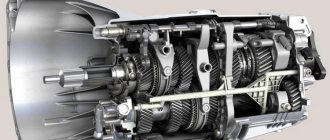
VAZ 2109 and 21099 cars are equipped with four- and five-speed manual transmissions. All gears, except reverse, are equipped with synchronizers. The box is also combined with the differentials.
Gearbox housing
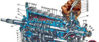
The gearbox housing is connected by pins to the clutch housing 29 during gearbox assembly and they together form a single unit. On the other hand, a rear cover 17 is attached to the gearbox housing, into which a breather 19 is pressed, connecting the crankcase cavity to the atmosphere. This prevents pressure build-up in the crankcase and oil leakage through the seals. The crankcase contains seats for the bearings of the primary and secondary shafts, as well as for the gearshift rod clamps. The clamps are closed with a common cover 8 (see Fig. 62), and the reverse lock is closed with plug 12. To fill the gearbox with oil, there is a hole closed with plug 2 (see Figure 59), and for draining the oil there is a hole closed with plug 3. The oil level should reach the bottom edge of the filler hole.
Useful tips
It is extremely important to monitor the serviceability of the gearbox, and if signs of breakdown are detected, fix them immediately. Do it yourself or with the help of a car service - this is your personal decision.
When operating a car in city conditions, you have to change gears more often. Therefore, it is recommended to use motor oil here. This ensures that the synchronizers remain effective longer. Transmission oil is better suited for highways, increasing the life of bearings and gears, although the synchronizer lasts less.
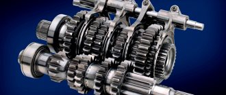
Internal structure of the box
Primary shaft
The input shaft 23 rotates in two bearings. The cylindrical roller bearing 26 is installed in the clutch housing socket, and the ball bearing is installed in the gearbox housing socket. The front end of the shaft at the exit from the crankcase is sealed with an oil seal, which is closed by the flange of the guide sleeve of the clutch release bearing. This flange is attached to the clutch housing with three bolts. The sleeve contains the clutch release bearing 31. The rear bearing 18 is fixed on the shaft with a nut and is held against axial displacement in the crankcase socket by an adjusting ring, which is pressed by the cover 17 to the gearbox housing. The nut is fixed by caulking its collar into the groove of the shaft.
The input shaft is made in the form of a block of drive gears of 1st, 2nd, 3rd, 4th gears and reverse. The clutch driven disc is located at the splined end of the shaft.
Malfunctions and their elimination
Gearbox repair largely depends on the nature and type of fault. There are several options for the breakdown of this unit, in each of which appropriate actions should be taken to eliminate them.
| Malfunction | Possible reasons | What do we have to do |
| There is noise in the gearbox |
|
|
| Gears are difficult to shift |
|
|
| Spontaneous gear disengagement occurs |
|
|
| Gears are switched on with noise and crackling |
|
|
| There is an oil leak from the gearbox |
|
|
In most cases, problems with the gearbox are eliminated by dismantling and disassembling it. Do not take on this type of work without the proper skills and experience.
Secondary shaft
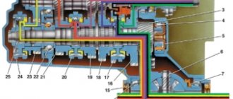
The secondary shaft 33 is manufactured integrally with the main gear drive gear. The front end of the shaft rests on a cylindrical roller bearing 32, and the rear end on a ball bearing 16. The front bearing is located in the clutch housing socket, into which a rubber plug is pressed for sealing. The rear bearing is secured to the shaft with a nut, which is fixed in the same way as on the input shaft. The secondary shaft is held together with the rear bearing from axial displacement by its mounting ring.
Driven gears of 1st, 2nd, 3rd and 4th gears and two synchronizers are installed on the secondary shaft on needle bearings with plastic cages. Bracelet-type needle bearings, which facilitates the installation of gears on the shaft. Installing gears on needle bearings reduces friction losses and increases gearbox efficiency. Gear 6 of the first gear is clamped between the thrust washer and the locking ring of the synchronizer hub of 1st, 2nd gears and reverse gear, gear 8 of the second gear is sandwiched between the second locking ring of the same synchronizer hub and the thrust half-rings 10 of the secondary shaft. The half rings are fixed on the shaft with a ball and a retaining ring 9, placed on the half rings. The gears of the 3rd and 4th gears are installed on the shaft in the same way. Only the needle bearing of gear 13 of the fourth gear is put on the bushing and a spacer ring is located between the bearing and the foot, and a thrust washer 15 is located between the bushing and the ball bearing.
Step-by-step instruction
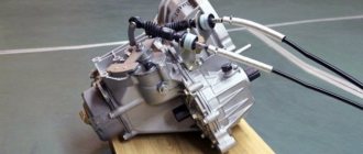
The gearbox weighs relatively little - 27 kg, but it is still not easy to remove it with your own hands, so invite an assistant. All work is carried out after installing the machine on the ramp or above the pit. Additionally, the car still needs to be jacked up and placed on supports so that the wheels are in the air.
First of all, remove the mudguard, the motor crater protection and disconnect the battery. Further:
- drain the gearbox oil;
- remove nuts from wheels and drives;
- remove the clutch cables and also the speedometer;
- disconnect all the ball joints by tightening the bolts holding them to the knuckles;
- dismantle the longitudinal tie;
- pull out all the drives included in the gearbox (you will need the help of a friend), remove the central nuts and remove them completely;
- unplug and remove the starter.
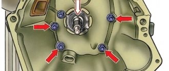
After this, all that remains is to disconnect the gearshift linkage and the gearbox itself from the engine (it is held in place by four nuts). But before this action, the power unit must be secured.
It is either hung out, leaning on the spar (or rather, on its glasses) or propped up from below with a jack.
The gearbox still needs to be disconnected from the body supports, and only then can it be removed. This is done in this way: the box is rocked a little and moved away from the engine by 10 cm - this is enough for the input shaft to leave the disc and clutch basket
In order not to damage the latter, you must act very carefully
The gearbox is installed in place after all problems and malfunctions associated with it have been fully eliminated.
Before the reassembly process you should:
- make sure that all elements affected by the dismantling process are in good condition;
- check the alignment of the clutch;
- Renew the lubricant on the splines of the release and input shaft bearing flanges.
When installing a gearbox on a car, the following scheme is used:
- the power unit is lowered on a jack or stretcher with a slope of 15 degrees;
- the box itself is lifted and inserted until it stops (do not try to tighten the engine and gearbox with bolts until it sits tightly in its designated place);
- tighten all four elements securing the gearbox to the engine;
- install “pillows” (supports) under it;
- attach the clutch cable and adjust its tension (its pedal is normally located a centimeter above the brake);
- return the previously removed starter together with the rear speed sensor to its place;
- install the flywheel protective housing;
- screw the speedometer cable and ground wire;
- connect the shift gear mechanism - its lever is aligned according to the marks made during dismantling;
- assemble the drive, install ball joints, couplers;
- put the car on the wheels and tighten the bolts on them;
- tighten the drive nuts;
- add fresh oil.
Synchronizer
The synchronizer consists of a hub 5 (Fig. 60), rigidly connected to the secondary shaft using splines, a sliding coupling 2, two locking rings 1, three cotters 4 with clamps 3 and springs, as well as synchronizer gears. The sliding clutch 7 (see Fig. 59) of the 1st to 2nd gear synchronizer has an outer ring for engaging reverse gear.
Rice. 60. Synchronizer parts:
1 — blocking ring; 2 — synchronizer sliding clutch; 3 — locking ball; 4 — retainer block; 5 — synchronizer clutch hub.
The synchronizer hub for 1st and 2nd gears is mounted on the splines of the secondary shaft and is secured on the shaft against axial displacement by two locking rings. The hub has six longitudinal grooves, three of which have slots for retainer springs. Rusks 4 (see Fig. 60) with retaining balls are installed in the same grooves. Springs press the clamps against the annular grooves of the coupling. On both sides of the hub there are bronze locking rings I with toothed rims, the pitch of which is equal to the pitch of the internal teeth of the sliding clutch and the gear rims of the gears of 1st and 2nd gears. The locking rings have six protrusions that fit into the grooves of the hub, with three short protrusions going into the grooves in which the clamps are located, and longer and wider ones into other grooves. These projections are installed in grooves with a lateral clearance equal to half the thickness of the coupling (hub) tooth, and limit the angle of rotation of the blocking ring relative to the hub. Thus, the hub rotates together with the blocking rings. With their conical surface, the blocking rings come into contact with the bevel belts of the 1st or 2nd gear gear at the moment the gear is engaged. To break the oil film at the point of contact and increase friction forces, especially fine threads and longitudinal grooves are cut on the conical surface of the ring.
The sliding clutch with its inner rim is seated on the outer gear rim of the hub and can move along the hub. To do this, the gear shift fork fits into the annular groove of the coupling. The ends of the coupling teeth are beveled at the same angle as the teeth of the blocking rings and synchronizer rims.
How to adjust the link?
You should drive the car onto a lift, pit or overpass. It is not recommended to carry out the procedure alone; you will need an assistant to switch the lever. You must proceed as follows:
- Crawl under the bottom, loosen the clamp located on the gearbox rod and remove the drive from the rod.
- Pull off the boot or remove this part altogether, unscrew the screw on the cardan.
- Use a hammer to carefully knock down the cardan shaft and remove the boot, if this was not done initially.
- If necessary, replace the oil seal.
- Installation is carried out similarly, but in reverse order.
After the above steps, you will need the help of a second person. He should sit behind the wheel, set the gearbox lever to neutral and tilt it slightly to the right. It should be held in this position until the universal joint clamp is properly tightened.
idler gear
Intermediate gear 5 (Fig. 61) for reverse gear is straight-cut. A bushing is pressed into its hole, through which axle 4 passes. It is installed in the holes of the clutch and gearbox housings. The reverse gear fork 6 fits into the groove of the gear.
Rice. 61. Reverse intermediate gear:
1 — gear selection current; 2 — gear selection rod lever; 3 — three-arm gear selection lever; 4 — axis of the reverse intermediate gear; 5 — reverse intermediate gear; 6 — reverse fork; 7 — reverse light switch; 8 — reverse fork clamp.
Step-by-step instruction
Drivers who do not want to tinker with their car use the services of a service station. The procedure for removing the gearbox can be done by yourself. True, you will need an assistant to carry it out.
What will you need?
To carry out work with the gearbox, the car must be driven into an inspection hole, raised using a lift, or installed on an overpass. Before you begin the process of removing the gearbox from a VAZ 2109, you need to drain the oil from it.
To remove the gearbox you will need:
- a set of keys;
- mount;
- for draining oil, a container with a volume of about 5 liters.
It is recommended to perform the procedure with an assistant.
Stages
The procedure for removing the gearbox on a VAZ 2109 includes the following steps:
- Before carrying out work, the car must be de-energized - disconnect the negative terminal on the battery.
- Next, the protection from the engine crankcase is removed. To do this, unscrew the screws with which it is attached to the body.
- The ground wire must be removed from the stud by unscrewing the bolt holding it.
- Next, release the clutch cable by loosening the nuts on the tip of the clutch cable. And then remove it from the clutch lever.
Disconnecting the clutch cable
- The next step is to disconnect the block supplying the power wires from the starter.
- Next, unscrew the nut and remove the power cable going to the battery from the stud.
- To disconnect the starter from the clutch basket, unscrew three mounting nuts.
Removing the starter By carefully pulling the starter towards you, you need to remove it from under the hood. - To perform further work, you need to move under the car. The gear shift drive rod is disconnected from the joint tip by loosening the clamp.
- Then the reverse sensor is disconnected.
Disconnect the reverse light connector - After unscrewing the fastening nut, disconnect the cable from the speedometer drive.
- The next stage is working with stretch marks. There is no need to remove them, just loosen the nuts securing them to the suspension arms.
- Then, the bolts securing the bracket to the car body or the nut that secures the braces to the bracket are unscrewed; the braces need to be moved apart so that they do not interfere.
- Next, the cotter pin of the nut is removed, with the help of which the ball is attached to the swing arm and the fastening nut of the ball is unscrewed.
- Now, using a puller, press the ball joint pin out of the strut swing arm.
- Then the steering tips are disconnected from the steering cams.
- At the next stage, using a small pry bar as a lever, you need to rest one of its ends against the drive hinge and push the grenade out of the box.
- After removing the drive, you need to install a technical plug in its place; you can use an old grenade. Now you can start removing the second one. If you do not install the plug and start removing the second drive, the differential gears located inside the box may shift, which will then be difficult to install due to the fact that the grenade shanks will not be able to get into place.
- Next, the mounting bolts are unscrewed and the shield is removed.
Removing the shield After this, you should loosen the screws and nut that secure the clutch housing and cylinder block together. - The next step is to fix the engine in a suspended state. This must be done, since when removing the VAZ 2109 gearbox, the mounting bolts of the power unit supports are unscrewed. To do this, a reliable wooden beam is installed on the front fenders, on which the engine will hang. First, material should be laid on the fenders to protect the paintwork, and wooden support bars should be placed under the beam in the area of the front pillar supports.
- Next, the engine is suspended using a strong rope or wire.
Suspending the engine Now you need to unscrew the nuts holding the rear support of the unit.Unscrew the left support fastener
- After unscrewing the nut, remove the left engine mount bolt.
- Then unscrew the nuts securing the motor to the gearbox and remove the support.
- Next, you need to finally unscrew all the fasteners on the other side of the gearbox. Then you should remove the box from the car by pulling it towards you. In this case, you need to act carefully so as not to break the clutch basket.
The procedure for removing the gearbox on a VAZ 2109 with your own hands is completed. Then you can continue repair work.
Differential
The differential is two-satellite. Its box 36 (see Fig. 59) rotates in two tapered bearings 35, the preload in which is adjusted by selecting the thickness of the ring 4. The driven gear 34 of the main gear is attached to the flange of the differential box, and the plastic gear 40 of the speedometer drive 42 is pressed onto the differential box. Gear 34 is in constant mesh with the drive gear of the main gear of the secondary shaft.
The satellites 37 and the semi-axial gears 39 have spherical bearing surfaces. The use of a solid sphere in the differential box, coupled with gears and satellites, made it possible to eliminate the support washers of the semi-axial gears.
The satellites are located on an axle 43, which is held in the holes of the differential box by retaining rings 44. The landing journals of the axle have grooves to retain lubricant. The holes of the semi-axial gears have internal splines into which the splined shanks of the housings of the internal hinges of the front wheel drives fit.
Features of replacing transmission fluid
Transmission oil must be changed at regular intervals, usually every 15-20 thousand kilometers. However, it may exhaust its resource earlier. This can be determined using a probe. Take a piece of white cloth and use a dipstick to transfer a drop of oil onto it. It is necessary to change the lubricant in cases where a drop of oil:
- colorless or has a black tint;
- contains metal particles or grains of dust;
- opaque and viscous;
- sticky to the touch;
- absorbs into fabric for a long time;
- cloudy or foamy.
Most often, reverse gear is difficult to engage if the oil has become cloudy. This is a sure sign that it has entered the engine. If the problem is not detected in a timely manner, you will soon need to carry out a complete gearbox repair or even an expensive transmission replacement.