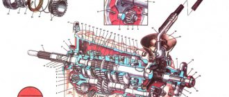
Disassembly and assembly of the gearbox
Disassembly and assembly of the gearbox
Repair and operation manual - Transmission VAZ-2101 - VAZ-2107 - Dismantling and assembling the gearbox
Disassembling and assembling the gearbox
Internal view of the clutch housing
The red arrows indicate the nuts securing the clutch housing to the gearbox.
The white arrow indicates the hole in the front cover for releasing oil from the gearbox housing to prevent oiling of the clutch discs.
Internal view of the rear gearbox cover
The arrow indicates the direction in which you need to move the lever to disengage it from the heads of the gear shift rods and remove the rear transmission cover.
1 – screw with an eye for fastening the tension spring of the gear shift lever; 2 – lever release spring; 3 – gear shift lever; 4 – screw for limiting the lateral travel of the lever.
Gear shift drive
1 – reverse fork; 2 – tension spring of the gear shift lever; 3 – guide cup of the lever; 4 – ball joint of the lever; 5 – gear shift lever; 6 – spherical washer; 7 – lever spring; 8 – retaining ring; 9 – damper locking sleeve; 10 – elastic damper bushings; 11 – damper spacer bushing; 12 – damper thrust pad; 13 – gear shift lever rod; 14 – shift fork for III and IV gears; 15 – shift fork for 1st and 2nd gears; 16 – fork rod for 1st and 2nd gears; 17 – fork rod for 3rd and 4th gears; 18 – reverse fork rod; 19 – blocking crackers; 20 – clamp cover; 21 – bushing; 22 – clamp spring; 23 – locking ball; 24 – rear cover of the gearbox; 25 – reverse light switch; 26 – remote bushing for the reverse fork rod.
Main shaft parts
1 – retaining ring; 2 – spring washer; 3 – bearing; 4 – input shaft; 5 – synchronizer spring; 6 – synchronizer blocking ring; 7 – retaining ring; 8 – bearing.
Secondary shaft parts
1 – retaining ring; 2 – spring washer; 3 – synchronizer hub; 4 – synchronizer clutch; 5 – retaining ring; 6 – synchronizer blocking ring; 7 – synchronizer spring; 8 – washer; 9 – third gear gear; 10 – secondary shaft; 11 – 2nd gear gear; 12 – washer; 13 – synchronizer spring; 14 – blocking ring; 15 – retaining ring; 16 – synchronizer hub; 17 – synchronizer clutch; 18 – retaining ring; 19 – synchronizer blocking ring; 20 – synchronizer spring; 21 – washer; 22 – 1st gear gear; 23 – bushing of the 1st gear gear; 24 – bearing; 25 – reverse gears; 26 – spring washer; 27 – retaining ring; 28 – speedometer drive gear; 29 – rear bearing; 30 – oil seal; 31 – elastic coupling flange; 32 – nut; 33 – seal; 34 – centering ring; 35 – retaining ring.
Shift Lever Parts
1 – tension spring bolt; 2 – washer; 3 – tension spring; 4 – gasket; 5 – guide cup; 6 – gasket; 7 – washer; 8 – limit bolt; 9 – gear shift lever; 10 – ball joint; 11 – spherical washer; 12 – spring; 13 – support washer; 14 – retaining ring; 15 – gasket; 16 – flange; 17 – spring washer; 18 – nut; 19 – cuff; 20 – inner cover; 21 – lever rod; 22 – handle; 23 – thrust pad; 24 – elastic bushing; 25 – spacer sleeve; 26 – elastic bushing; 27 – locking sleeve.
Gearbox disassembly
EXECUTION ORDER
1. Wash the gearbox and install it on a stand. Drain the oil and remove the bottom cover with gasket.
2. Remove the clutch release fork, and from the guide sleeve of the front cover of the gearbox, remove the clutch assembly with bearing and connecting spring.
3. Remove the clutch housing with the gasket and the front cover of the gearbox (along with the oil seal and spring washer) (see Fig. Internal view of the clutch housing).
4. Remove the speedometer drive with the gasket and the reverse light switch, being careful not to deform its housing.
5. Remove the bolt securing the shift fork for 3rd and 4th gears. Install clamp 41.7816.4068 on the input shaft or engage two gears at the same time. This will prevent the primary, secondary and intermediate shafts from turning and will allow subsequent disassembly operations to be performed.
6. Remove the snap ring from the end of the transmission output shaft.
7. Having straightened the lock washer, unscrew the nut a few turns to move the centering ring of the elastic coupling, and tighten the nut again. Using a pusher A.40006/1 with a puller A.40005/4, remove the centering ring of the elastic coupling of the cardan shaft from the end of the secondary shaft.
8. Remove the seal of the centering ring of the elastic coupling from the end of the secondary shaft, unscrew the nut and use puller 4 A.40005/3/9B/9 to remove the flange of the elastic coupling 1 (2 – bolts securing the device to the flange; 3 – strip 9C of puller A.40005/ 3).
9. Remove the rear cover of the gearbox by unscrewing the nuts securing it and screw 4 (see Fig. Internal view of the rear cover of the gearbox) limiting the lateral travel of the lever, and also moving the gear shift lever to the left to free it from the gear shift rods.
10. Remove the rear bearing from the output shaft. Remove the speedometer drive gear.
11. Remove the fork with the spacer bushing from the reverse control rod, and the reverse intermediate gear from the axle.
12. Remove the reverse drive gear retaining ring from the intermediate shaft, remove the gear and spring washer.
13. Remove the reverse driven gear retaining ring from the output shaft, pressing the spring washer with mandrel 41.7816.4069 to relieve the load on the retaining ring. Remove the reverse driven gear and spring washer.
14. Using shaped mandrels (such as screwdrivers) and rod drifts, remove the front and rear intermediate shaft bearings from the gearbox housing. Make marks on the inner rings of the double-row front bearing, according to which these rings should be installed in their original places in the outer ring of the bearing.
15. Remove the intermediate shaft from the gearbox housing by tilting it as shown in the figure.
16. Remove cover 20 (see Fig. Gear shift drive) of the rod clamps along with the gasket, remove the springs and clamp balls. Remove rod 18 for reverse gear and rod 17 for shift fork for 3rd and 4th gears from the gearbox housing. Unscrew the bolt securing the forks of 1st and 2nd gears, remove the rod and forks. When removing the rods, simultaneously remove three locking blocks 19.
17. Unscrew the screws securing the locking plate of the secondary shaft intermediate bearing with a drill screwdriver and remove the locking plate of the secondary shaft intermediate bearing and the axis of the reverse intermediate gear (the arrow indicates the direction of the impact stroke of the screwdriver cage when struck with a hammer).
18. Using mandrels (such as screwdrivers), remove the input shaft along with the bearing and synchronizer ring and remove the needle bearing from the front end of the secondary shaft.
19. Knock the secondary shaft out of the intermediate bearing, remove the intermediate bearing and, tilting it as shown in the figure, remove the secondary shaft assembled with gears, clutches and synchronizer rings from the crankcase. Remove the synchronizer clutch for 3rd and 4th gears from the shaft.
Disassembling the gearbox input shaft
20. Remove the retaining ring 7 (see Fig. Parts of the input shaft), the blocking ring 6 and the synchronizer spring 5.
21. Place the shaft on the press and, using a mandrel 41.7816.4069, compress the spring washer 2, remove the locking ring 1, then the spring washer and bearing 3.
Dismantling the secondary shaft of the gearbox
22. Remove gear 22 from the rear side of the shaft (see Fig. Details of the secondary shaft) of the 1st gear with sleeve 23, hub 16 with a sliding clutch for switching 1st and 2nd gears, gear 11 of the 2nd gear together with the synchronizer blocking ring 14.
23. Install the secondary shaft with a mandrel 41.7816.4069 on a press, place support half-rings 3 under the 3rd gear gear, and, pressing the mandrel on the spring washer, remove the locking ring 2, then the spring washer 4, the hub of the sliding clutch for shifting 3rd and 4th gears and the gear III gear.
Disassembling the gear shift lever and rear cover
24. Remove the cuff 19 (see Fig. Parts of the gear shift lever), the lever cover 20, then the lock ring 14, washer 13, spring 12 and spherical washer 11.
25. Unscrew the nuts securing the flange 16, disconnect the tension spring 3 of the lever from the eye of the bolt 1 and remove the lever together with the flange, support 10 and cup 5.
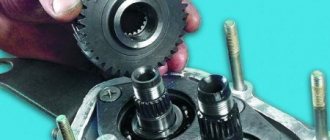
Installing the reverse gear retaining ring on the secondary shaft
1 – spring washer; 2 – mandrel 41.7816.4069; 3 – locking ring; 4 – reverse gear of the secondary shaft.
Gearbox assembly
EXECUTION ORDER
The gearbox is assembled in the reverse order of disassembly. Please note that: – spring 22 (see Fig. Gear shift drive) of the reverse fork rod lock ball differs from others in elasticity, it is painted green or has a cadmium coating; – when installing the clutch housing with the front cover of the gearbox, the hole in the front cover should be located as shown in Fig. Internal view of the clutch housing; – before installation, coat the working surface of the oil seals with LITOL-24 lubricant; – when installing the reverse gear retaining ring, use mandrel 41.7816.4069, and when installing bearings and shaft seals, use mandrels 41.7853.4028, 41.7853.4032, 41.7853.4039.
Quote
Possible malfunctions of the MTZ gearbox
Problems when starting off and with steering in motion associated with gearbox failure can be divided into two groups:
- Difficulties in fixing the selected speed (poor retention, “knocking out” the gear, etc.).
- Extraneous sounds made by the gearbox when shifting gears or while the tractor is moving.
The first stage of the gearbox, which doubles the available speeds, complicates the design of the box. Externally similar symptoms can be caused by the breakdown of various parts inside the unit; an accurate diagnosis can be made after partial or complete dismantling of the gearbox. Problems with the gearbox are the same for MTZ-80 with one drive axle and MTZ-82 with two axles.
Bearings.
Knocking out the speed
A shift out of gear while driving can be caused by problems with the shift forks, retainer springs, shafts, or bearings. If the gears are not properly engaged, the lever may return to the neutral position.
Impossibility or poor gear engagement
The problem with turning on speeds can be caused by the same reasons as their spontaneous switching off or switching, i.e. with defects in forks or retaining springs. The distance between the gear shift bars should not be more than 1.6 mm. The second source of problems with gear shifting is a malfunction of the clutch mechanism. The tractor may stall when starting due to defects in the fuel supply control system.
Rumble and grinding noise when the gearbox operates
Extraneous sounds when the gearbox is running can be of 2 types:
- constant (hum or noise);
- discrete (knock).
The presence of constant noise indicates wear of the shaft mounts. If the problem is not corrected, the shaft may break off the mounting and jam the transmission. Another source of persistent noise can be bearing wear. The reason for the simultaneous occurrence of noise and free play of the reduction gear control lever may be wear of the fork. Uncharacteristic sounds in the final drive gearbox may indicate a malfunction of the front axle.
Breakdown of the gearbox shift mechanism
A malfunction of the gear shift unit can result in play, which makes it impossible to set the lever to the desired position. The reasons may be:
- deformation of the springs during operation, as a result of which, in a compressed state, their length exceeds the maximum permissible;
- wear of shift forks;
- broken grooves of sliding carriages.
If there are signs of wear on the tip of the MTZ gearbox shift lever, it must be replaced.
Tension and compression deformation of a spring.
Dismantling
To dismantle the box, we recommend that you rely on the instructions, strictly follow the sequence and reinforce your skills with visual videos.
- Disconnect the negative terminal from the battery and drain the oil from the gearbox system.
- Unscrew the bolts that hold the crankcase guard in place and remove it.
- Disconnect the ground (wire) from the clutch housing.
- At the end of the clutch cable, loosen the tension on the nuts slightly.
- Remove the cable end from the clutch lever.
- Disconnect the block from the traction relay.
- Disconnect the wire going to the starter traction relay.
- Dismantle the starter itself directly.
- Disconnect the drive rod from the joint tip. We are talking about traction, which switches gears.
- Disconnect the cable from the car's speedometer drive.
- Unscrew the tie rod ball joint.
- Remove and press the steering rod hinge pin out of the strut swing arm.
- The shank of the inner CV joint of the front wheel drive should be pressed out and moved to the side.
- Disconnect the second CV joint.
- Remove the clutch housing shield.
- Release the gearbox from the fasteners holding it to the engine.
- Remove the box.
Removing the gearbox
Be sure to move it horizontally away from the engine before directly removing the gearbox. Then disengage the input shaft. Be careful not to damage the clutch spring petals.
Required Tools
VAZ-2109 gearbox maintenance and repair sooner or later has to be done by every owner of a domestic car.
To repair a gearbox with your own hands, you need to stock up on the necessary set of tools in advance:
- 2 types of hammers, one of which is made of rubber, and the other is ordinary;
- screwdrivers with different tips;
- mark;
- set of union heads;
- impact screwdriver;
- a wrench to help remove locking type rings.
Useful tips
It is extremely important to monitor the serviceability of the gearbox, and if signs of breakdown are detected, fix them immediately. Do it yourself or with the help of a car service - this is your personal decision.
When operating a car in city conditions, you have to change gears more often. Therefore, it is recommended to use motor oil here. This ensures that the synchronizers remain effective longer. Transmission oil is better suited for highways, increasing the life of bearings and gears, although the synchronizer lasts less.
Box device
How to independently diagnose (defect) an automatic automatic transmission
Self-diagnosis of automatic transmissions should be carried out in a certain sequence.
Steps to check an automatic transmission:
- checking the transmission fluid level, gearbox characteristics and condition;
- quick check of the functioning of the internal combustion engine in idle mode, connectors and condition of the wiring, stage selection cable and throttle cable;
- reading fault codes of engine and automatic transmission control units;
- checking the functioning of the vehicle at full engine power and a complete stop;
- diagnostics when driving in different modes;
- checking the pressure level in the control system.
Without visiting a service station, you can check your car for errors using the Rokodil ScanX universal scanner.
The device comes with detailed instructions for connecting it and selecting software.
Checking the throttle cable
The cable that controls the throttle valve connects the control mechanism of the box with the throttle assembly or fuel injection pump control. A long period of operation leads to damage to the cable sheath, its drying out, shortening and coming out of the fastening.