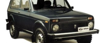
During the operation of the car, problems may arise that can only be solved after studying the electrical circuits. The article presents detailed wiring diagrams for the Lada 4×4 SUV (VAZ 2121), which will help you not only repair the car, but will also be useful when installing additional electrical equipment, for example, a car alarm, DVR and other accessories..
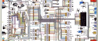
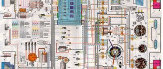
Electrical diagram of VAZ-21213
1 — headlights; 2 — side direction indicators; 3 — electric motor for windshield washer; 4 — headlight washer motor*; 5 - switch; 6 - battery; 7 - starter; 8 - generator; 9 — headlights; 10 — gearmotors for headlight cleaners*; 11 — sound signal; 12 — spark plugs; 13 — carburetor limit switch; 14 — carburetor solenoid valve; 15 — ignition coil; 16 — windshield wiper gearmotor; 17 — carburetor solenoid valve control unit; 18 — ignition distributor sensor; 19 — coolant temperature indicator sensor; 20-oil pressure warning lamp sensor; 21 — plug socket for a portable lamp**; 22 — brake fluid level warning lamp sensor; 23 — windshield wiper relay; 24 — relay for turning on the rear fog light***; 25 — relay for turning on the heated rear window; 26 — relay for turning on headlight cleaners and washer*; 27 — relay for turning on low beam headlights; 28 — relay for turning on the high beam headlights; 29 — ignition relay; 30 — starter activation relay; 31 — relay-breaker for alarm and direction indicators; 32 — heater electric motor; 33 — additional resistor of the heater electric motor; 34 — backlight lamps for heater control levers; 35 — external lighting switch; 36 — main fuse block; 37 — additional fuse block; 38 — reverse light switch; 39 — brake light switch; 40 — instrument lighting regulator; 41 — ignition switch; 42 — three-lever switch; 43 — alarm switch; 44 — tailgate glass cleaner and washer switch*; 45 — heater motor switch; 46 — switch for heating the rear door glass; 47 — rear fog light switch; 48 — lamp switches located in the door pillars; 49 — interior lamps; 50 - cigarette lighter; 51 — switch for the warning lamp for covering the carburetor air damper; 52 — control lamp for covering the carburetor air damper; 53 - switch for differential lock warning lamp; 54 — parking brake warning lamp switch; 55 — sensor for level indicator and fuel reserve; 56 — instrument cluster; 57 — tailgate glass washer motor; 58 — rear lights; 59 — block for connecting additional brake lights; 60 — blocks for connecting side marker indicators; 61 — pads for connecting to the heated glass element of the tailgate; 62 — license plate lights; 63 — gear motor for tailgate glass cleaner.
The order of conditional numbering of plugs in the blocks : a - windshield wipers, headlights and tailgate glass, windshield wiper relay breaker; b — ignition distributor sensor; c — relay-interrupter for alarm and direction indicators; g - switch; d — three-lever switch; e — alarm switch; g — relay for turning on the rear fog light; h — rear lights (numbering of terminals in order from top to bottom); and — instrument clusters.
In the instrument panel wiring harness, the second ends of the white wires are brought together to one point, which is connected to the instrument lighting control. The second ends of the black wires are also brought together to a point connected to ground. The second ends of the yellow wires with a blue stripe are brought together to a point connected to terminal “A” of the main fuse block. And the second ends of the orange wires are also brought together to a point connected to terminal “B” of the main fuse block.
* Installed on parts of manufactured cars; **not installed since 2000; *** installed since 2001. Previously, the rear fog light was switched on directly by switch 47, powered by fuse 3 of the additional fuse box.
Relays and fuses Niva
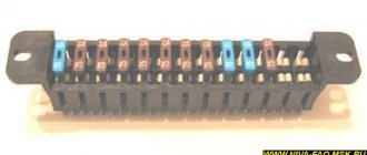
The main fuse box is located in the passenger compartment under the instrument panel, to the left of the steering wheel. To access the blocks, pull the latch located on top of the blocks and remove the cover.
- engine control system fuse box;
- windshield wiper relay;
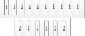
- fuse blocks VAZ-2121;
- engine control system relay block.
Main fuse box
| Designation and current, A | Protected Circuits |
| F1 (16) | Heater Blower Motor Switch, Tailgate Defroster Switch, Tailgate Wiper Motor, Tailgate Wiper/Washer Switch (Windshield Washer Pump) |
| F2 (8) | Steering column switch, windshield wiper motor, hazard warning switch, breaker relay (in turn signal mode), reverse light switch, instrument cluster (coolant temperature gauge, fuel level gauge, tachometer, indicator lamps: turn indicators, differential locks, parking brake, emergency condition of the service brake system, insufficient oil pressure, fuel reserve, battery charge) |
| F3 (8) | Left headlight (high beam), high beam indicator lamp |
| F4 (8) | Right headlight (high beam) |
| F5 (8) | Left headlight (low beam) |
| F6 (8) | Right headlight (low beam) |
| F7 (8) | Side light lamps in the left front and left rear lights, license plate lights, side light indicator lamp |
| F8 (8) | Side light lamps in the right front and right rear lamps, backlight lamps for the instrument cluster, cigarette lighter, switches, heating and ventilation control unit |
| F9 (16) | Hazard switch, breaker relay (in hazard mode), heated tailgate glass relay contacts |
| F10 (16) | Sound signal, interior lamps, brake lamps in the rear lights |
| F11 (8) | Reserve |
| F12 (8) | Reserve |
| F13 (8) | Fog light relay contacts in rear lights |
| F14 (16) | Cigarette lighter fuse |
| F15 (16) | Reserve |
| F16 (8) | Reserve |
Engine control system fuse box
| Designation and current, A | Protected Circuits |
| F1 (30) | Right electric fan relay contacts |
| F2(30) | Left electric fan relay contacts |
| F3 (15) | Relay windings of the right and left electric fans, controller, injectors, ignition coil |
| F4 (15) | Heating elements for control and diagnostic oxygen concentration sensors, phase sensor, mass air flow sensor, canister purge valve |
On the left under the instrument panel, on the body, there is a block of four fuses for the engine management system and a diagnostic connector. To access the block, unscrew two self-tapping screws and remove the casing.
Engine control relay
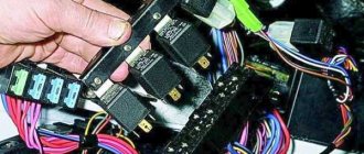
Below the main fuse box are the engine management system relays.
- ignition relay;
- Niva main relay;
- right electric fan relay;
- left electric fan relay;
- fuel pump relay;
- fuel pump fuse (F5, 15 A).
Relay box under the dashboard
Under the instrument panel, just above the gas pedal, there is a block with four relays.
- Niva rear fog light relay;
- relay for turning on the heated glass of the tailgate;
- low beam headlight relay;
- high beam headlight relay.
Above this block, behind the instrument cluster, there is a turn signal and hazard warning relay.
Blocks for LADA 4X4 2022
The relay and fuse diagram may differ depending on the configuration and production date of the vehicle. Current diagrams of the mounting block are presented in the operating manual as of the date of manufacture of the vehicle.
The fuses are grouped in two fuse blocks located on the left under the instrument panel. The fuse ratings and the circuits they protect are shown in the table.
The fuses for the VAZ 2131 injection system are located in a separate block on the left side under the instrument panel.
The electric motors of VAZ-2121 gearmotors (windshield wipers, tailgate glass, headlights - if installed) are protected by automatic reusable bimetallic fuses. The power supply circuit of the injection system is protected by a fuse-link made of wire with a conductor of reduced cross-section (1 mm2). The battery charging, ignition, engine starting, and “generator – ignition switch – fuse box” circuits are not protected. Powerful consumers (starter, headlights, electric motors Niva 2131 cooling system fans, electric fuel pump, etc.) are connected via a relay.
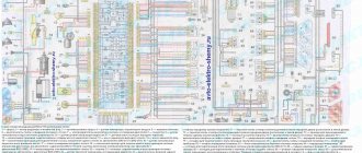
Electrical diagram of VAZ-2121
1 — headlights; 2 — side direction indicators; 3 — headlight washer motor*; 4 - voltage regulator; 5 — battery charge warning lamp relay; 6 - battery; 7 - starter; 8 - generator; 9 — headlights; 10 — gearmotors for headlight cleaners*; 11 — sound signals; 12-spark plugs; 13 — carburetor solenoid valve; 14 — ignition coil; 15 — windshield wiper gearmotor; 16 — coolant temperature indicator sensor; 17 — ignition distributor; 18 — windshield washer electric motor; 19 — oil pressure indicator sensor; 20 — oil pressure warning lamp sensor; 21 — brake fluid level warning lamp sensor; 22 — plug socket for a portable lamp; 23 — relay for turning on headlight cleaners and washer*; 24 — relay for turning on low beam headlights; 25 — relay for turning on the high beam headlights; 26 — windshield wiper relay; 27 — additional fuse block; 28 — main fuse block; 29 — additional resistor of the heater electric motor; 30 — reverse light switch; 31 — brake light switch; 32 — heater electric motor; 33 — relay-interrupter for alarm and direction indicators; 34 — parking brake warning lamp switch; 35 — alarm switch**; 36 — cigarette lighter; 37 — switch for cleaners and headlight washers*; 38 — heater motor switch; 39- external lighting switch; 40 — three-lever switch; 41 — ignition switch; 42 — instrument lighting switch; 43 — lamp switches located in the door pillars; 44 — interior lamps; 45 — oil pressure gauge with insufficient pressure warning lamp; 46 — fuel level indicator with reserve warning lamp; 47 — tachometer; 48 — parking brake warning lamp; 49 — battery charge indicator lamp; 50 — control lamp for the carburetor air damper; 51 — side light indicator lamp; 52 — turn signal indicator lamp; 53 — control lamp for high beam headlights; 54 — speedometer; 55 — carburetor air damper warning lamp switch; 56 — relay-interrupter for the parking brake warning lamp; 57 — coolant temperature indicator; 58 — brake fluid level warning lamp; 59 — differential lock warning lamp; 60 - switch for differential lock warning lamp; 61 — rear lights; 62 — license plate lights; 63-sensor for level indicator and fuel reserve.
The order of conditional numbering of plugs in the blocks : a - windshield and headlight wipers, windshield wiper relay breaker; b — relay-interrupter for alarm and direction indicators; c — three-lever switch; d — hazard warning switch.
* Installed on parts of manufactured cars; ** on cars produced in the 90s, due to the installation of breaker relays 33 without the fifth terminal, the brown wire connecting switch 35 to breaker relay 33 is missing.
How to check if the battery is charging
Before looking for a fault in the charging circuit, it is necessary to find out whether this very undercharging actually exists. After all, the problem could be:
- in charge indication circuits;
- in a faulty battery.
Healthy! To check, we use a DC voltmeter with a measurement limit of 20 V or a multimeter (tester). Both pointer and digital devices are suitable. The accuracy of both will be sufficient.
We connect a voltmeter or multimeter turned on in the DC voltage measurement mode to a limit of at least 20 V. We start the engine and raise its speed to 1,000 per minute. If the voltmeter shows a voltage in the range of 13.5-14.2 V, then the charging circuits are OK. The fault is with the charging indication elements that mislead us, or with the battery.
In the first case, we check the control circuits (their circuits and testing algorithm will be described below), in the second case, we test the battery using a load fork.
Engine control system VAZ-21214
Connection diagram of the VAZ-21214 engine management system with central fuel injection under US-83 toxicity standards with controller 21214-1411010 (EFI-4 type) on VAZ-21214 vehicles : 1 - “CHECK ENGINE” control lamp; 2 — instrument cluster (fragments); 3 — electric fans of the engine cooling system*; 4 — electric heater of the intake pipe; 5 — air temperature sensor; 6 — absolute pressure sensor; 7 — coolant temperature sensor; 8 — block connected to the throttle position sensor; 9 — central fuel injection unit; 10 — block connected to the idle speed regulator; 11 — block connected to the nozzle; 12 — diagnostic block; 13 - controller; 14 — knock sensor; 15 — speed sensor; 16 — oxygen concentration sensor; 17 - adsorber; 18 — battery; 19 - main relay; 20 — fuse block of the engine control system; 21 — relay for turning on the electric fuel pump; 22 — relay for turning on the electric fan*; 23 — relay for turning on the electric heater of the inlet pipe; 24 — electric heater protection fuse; 25 — starter activation relay; 26 — ignition relay; 27 — main car fuse box (fragment); 28 — spark plugs; 29 — tachometer; 30 — electric fuel pump with fuel level sensor; 31 — ignition module; 32 — crankshaft position sensor; 33 - courtesy light switch, located on the driver's door pillar; 34 — control unit of the automobile anti-theft system**; 35 — status indicator of the car anti-theft system**; A - wire going to plug “50” of the ignition switch; B - wire going to plug “15” of the ignition switch; B - wire going to terminal “30” of the generator; G - rear wiring harness wires connected to the fuel level indicator; D - rear wiring harness wire connected to switch 33.
The order of conditional numbering of plugs in blocks : a - controller; b — control unit of the automobile anti-theft system; c — indicator of the state of the automobile anti-theft system; g — speed sensor; d — central fuel injection unit; e — electric fuel pump and oxygen concentration sensor; g — ignition module; h - absolute pressure sensor.
Connection diagram of the VAZ-21214 engine management system with distributed fuel injection under Euro-2 toxicity standards with controller 2123-1411020-10 (type MP 7.0) on VAZ-21214 vehicles : 1 - control lamp of the engine management system; 2 — instrument cluster (fragments); 3 — electric fans of the engine cooling system; 4 — courtesy light switch, located on the driver’s door pillar; 5 — status indicator of the car anti-theft system; 6 — control unit of the automobile anti-theft system; 7-coolant temperature sensor; 8 — air flow sensor; 9 — throttle assembly; 10 — block connected to the throttle position sensor; 11 — block connected to the idle speed regulator; 12 - controller; 13 — oxygen concentration sensor; 14 — knock sensor; 15 — crankshaft position sensor; 16 — speed sensor; 17 - adsorber; 18 — battery; 19 - main relay; 20 — diagnostic block; 21 — fuse block of the engine control system; 22 — relay for turning on the electric fuel pump; 23 — relay for turning on electric fans; 24 — main car fuse box (fragment); 25 — block connected to the additional wiring harness*; 26 — ignition module; 27 - tachometer; 28 — electric fuel pump with fuel level sensor; 29 — nozzles; 30 — spark plugs; A - rear wiring harness wire connected to switch 4; B - wires connected to plug “1” of fuse block 24 (one wire goes to plug “15” of the ignition switch, and the other to plug “85” of the ignition relay); B - rear wiring harness wires connected to the fuel level indicator.
The order of conditional numbering of plugs in blocks : a - controller; b — control unit of the automobile anti-theft system; in - air flow sensor; g — speed sensor; d — indicator of the state of the automobile anti-theft system; e — electric fuel pump and oxygen concentration sensor; g - throttle pipe; h — ignition module.
Electrical connection diagram of the EURO-4 ME17.9.7 ECM for cars of the LADA 4x4 family with engine 21214
:
1 – controller; 2 – diagnostic block; 3 – mass air flow sensor; 4 – coolant temperature sensor; 5 – phase sensor; 6 – electric fuel pump module; 7 – pads for the instrument panel harness and rear harness; 8 – ignition coils; 9 – spark plugs; 10 – electronic accelerator pedal; 11 – throttle pipe with electric drive; 12 – electric fan of the engine cooling system, right; 13 – electric fan of the engine cooling system, left; 14 – knock sensor; 15 – pads for the ignition system harness and injector harness; 16 – nozzles; 17 – solenoid valve for purge of the adsorber; 18 – control oxygen sensor; 19 – diagnostic oxygen sensor; 20 – crankshaft position sensor; 21 – APS control unit; 22 – APS status indicator; 23 – ECM fuse block; 24 – fuse for the power supply circuit of the electric fuel pump; 25 – electric fuel pump relay; 26 – left engine cooling system electric fan relay; 27 – relay for the electric fan of the right engine cooling system; 28 – ignition relay; 29 – pads for the ignition system harness and instrument panel harness; 30 – instrument cluster; 31 – vehicle speed sensor; 32 – brake signal switch; 33 – clutch pedal position signal switch; 34 – main fuse block; 35 – additional relay; 36 – contacts of the instrument panel harness pads and the front harness; 37 – contacts of the instrument panel harness and rear harness pads
Download all schemes in high quality To download files you need to log in to the site
turbomotor412 posted a number of diagrams in his BZ:
Let us remind you that you will find detailed instructions for repairing the Lada 4×4 SUV in this section.
0 0 0 0 0 0
Share on social networks:
The belt has stretched or broken
The drive belt for the generator and water pump from the engine shaft does not break very often, but it stretches regularly. As a result, it begins to slip on the pulleys, the generator, especially under load (high beams plus air conditioning, etc.), does not develop the required speed, and the voltage at its output drops. As a result, the battery is undercharged and may even be discharged, helping the “exhausted” generator and feeding the on-board network with its energy.
Poor belt tension is characterized by a drop in the voltage of the on-board network and a peculiar whistle when the speed increases sharply, especially in wet weather. The problem is treated quite simply. Find the generator mounting bolt on the tension bar. We loosen it, use a pry bar to move the generator to normal belt tension and tighten the bolt.
Expert opinion
Alexey Bartosh
Specialist in repair and maintenance of electrical equipment and industrial electronics.
Ask a Question
Healthy! An over-tightened belt is just as bad as a loose one. It can tear, leaving you spending the night on the road, and will very quickly stretch again. So you shouldn’t tighten the belt “for future use”. Its tension force should be approximately the same as indicated in the diagram below.
Features of the modification
Electrical diagram describing the VAZ 2121 Niva carburetor.
First of all, the changes affected the engine control system and control devices. In particular:
- The wiring diagram for Niva 21213 received an additional wiring harness in the engine compartment for connecting a microcontroller and sensors;
- On the Niva model of recent years of production, a more advanced power unit with the VAZ-21214 index is installed. Instead of a carburetor, it has a fuel frame with injectors from GM. The price of a car with injection has increased because of this;
- The instrument panel has changed - the design is borrowed from the VAZ 2108 model.
Ignition system
The VAZ 21213 engine uses a non-contact ignition system consisting of:
- ignition distributor sensor (marking 3810.3706). It is responsible for creating control pulses supplied to the electronic switch;
- switch (model marking – 3620.3734) in climatic version U2.1 (corresponds to GOST 15150);
- ignition coils (marking 27.3705).
For reference: this device provides increased spark energy, which helps start the engine in cold weather, and also improves the performance of the power unit when operating the vehicle on low-quality fuel.
Dashboard
A modified instrument panel appeared on the car. In particular, instead of a voltmeter, the manufacturer installed a low battery discharge lamp (no. 12 in the diagram).
Tip: if you often operate your car in off-road conditions, you can buy and connect a voltmeter to the instrument panel yourself. It is more informative than a warning light and will allow you to identify electrical system faults long before the battery discharges.
Search form
Brake light switch. At this moment, the holes fall under vacuum; fuel from the float chamber through jet 26 rises up the tube, air is mixed from air jet 14, and the emulsion flows through the emulsion channel through the outlet holes under the throttle valve.
Below is a diagram of the VAZ You also have the option to opt-out of these cookies. The transition system of the second chamber ensures a smooth transition of engine operation at the moment the throttle valve of the second chamber begins to open.
When the generator is running, the battery is charged. Glove box light switch.
Only the main dosing system of the first chamber operates in throttling mode. These cookies will be stored in your browser only with your consent.
The starting device ensures the preparation of a rich combustible mixture when starting a cold engine. Scheme of operation of the starting device. Out of these cookies, the cookies that are categorized as necessary are stored on your browser as they are as essential for the working of basic functionalities of the website.
Limit switch Electromagnetic. VAZ is the same carburetor with a similar engine size. If it is a carburetor, then the electrical wiring will have certain differences. Air damper drive rod.
Circuit breakers
Through the main fuel jets 36 and 28, fuel enters the emulsion wells. Similar wires are insufficient wiring of the elk, which did not equip the circuit to realize its endless potential. Consciously: in Russia and the leading CIS countries it was not officially applied with a diesel snare. VAZ is the same carburetor with a similar engine size. When the throttle valve is opened sharply, the cam presses the lever 40 and, through a spring in the pusher, acts on the diaphragm 39, overcoming the resistance of the return spring.
Adjusting screw 1 allows you to adjust the amount of opening of the damper. A 30 A fuse protects the power supply circuit of the electric radiator fans, and three 15 A fuses protect the electric fuel pump, the control unit, the constant power input and the injection system main relay circuit, respectively, see Ignition coil. VAZ is the same carburetor with a similar engine size. Excitation of the Niva generator The simplest and most reliable circuit for supplying voltage to the excitation windings of the generator
Chevrolet Niva spare parts stores in Moscow
You can select the part you are interested in for Chevrolet NIVA Chevrolet NIVA cars and order and purchase spare parts in Moscow online, as well as install them in one of our service centers according to the standards of an official dealer
Specify the make, model and VIN number of the car for a more accurate selection of spare parts or select it from the garage.
Indicate the catalog numbers of spare parts or simply write down which spare parts you need in a list, and our specialist will select the correct numbers, check prices and availability.
Pay for your order online or in our offices upon receipt. Pick it up at a car dealership convenient for you in Moscow.
Lada 4×4 3D 2121 › Logbook › Electric fans 21214 in 2121
Just a short note about the installation. Inspired by an article on Niva-Fak and tired of constant boiling, I broke my piggy bank and went to the local car market, where I purchased: 1. Electric valves 21214 2. Tee for a sensor from a GAZelle 3. Sensor TM-108 87-92 degrees 4. Relay 711.3747-01 5. Fuse 30A 6. VAZ-2101 heater control button 7. Rubber radiator pads from VAZ-2108 2 pcs. So, part one is installation. In the article at the link, the guy writes that he barely inserted the valves into the face, raised the steering wheel, tightened it, sawed it off and installed it - DON’T DO THIS!
The valves rest with their lower legs against the holes in the muzzle, and with the upper rubber bands they press the radius against the top of the muzzle, and that’s it. Nothing warps or rubs, everything works PERFECTLY. And the sides on the upper elastic bands hint to me personally that this is how it should be, there is no need to cram in what cannot be squeezed in. At the same time, they unscrewed the native Carlson so that it would not take away the power from the already shaky Pihl. Also in the process, the gene belt was replaced, because it was slightly worn. The threesome with the sensor was cut into the lower pipe, it didn’t go in without a curse, but it went in.
The photo is not so great, but the car looks clearly better
Part two - connection. The diagram in the article, unlike the instructions, is more clear. Everything was connected according to it, only the wires on the button were swapped: ground with any other.
Result: the scheme works, but they hum - mother, don’t worry. for some reason you immediately feel like you’re on a Junkers
The sensor turned out to be too hot - according to the display meter, it turns on when the needle has already crept well over 90. The voltage at 2000 rpm with the valves on drops to 13 volts
Maintenance Tips
The factory instructions require troubleshooting the ignition system in the following sequence:
- From the ignition switch (terminal 15), connect the wire to the coil (terminal +B) to a test lamp;
- Connect its negative terminal to ground;
- Turn on the ignition - turn the key in the lock to position “II”;
- If the control lamp lights up, then the circuit is working. If not, look for damage to the wire;
- With the ignition on, pull out the central wire from the coil from the distributor;
- Bring its metal tip to the cylinder block so that a gap of 3-4 mm forms between them;
- Turn on the starter for a few seconds;
- If the spark jumps, the coil is working.
Tip: you can quickly check the switch in one way - take it from a working car. If the car starts with the new switch, then you need to buy a new one.
Operating principle
The cooling system of VAZ Niva models does not come into contact with the atmosphere in operating condition, and therefore requires pressure. The coolant is antifreeze with a freezing point of 40 degrees Celsius. The composition of the solution is water and ethylene glycol. The total volume of the cooling circuit is 10.7 liters. Antifreeze can boil after a temperature of +110 degrees Celsius.
The main functional unit in the system is the thermostatic valve, which distributes the coolant flow depending on the engine temperature. The thermostat, controlled by a temperature-sensitive sensor, regulates the direction of movement of antifreeze. A simplified work flow looks like this:
In summer and during transition periods in models with an injector, the movement of the cooler is limited by a special tap. The Niva Chevrolet model does not have such a blocker, so the heating is turned off by directing the air flow past the heat exchanger.
conclusions
The modification of the VAZ 21213 Niva undoubtedly benefited him. The new engine and improved ignition system have made its operation even easier and more confident in harsh conditions.
Every modern car today is equipped with an electrical part. The electrical diagram of the VAZ 21214 Niva injector allows, if necessary, to find all the elements included in the on-board network, which is especially important when faults occur in the wiring. Everything a driver needs to know about electrics in domestic SUVs is described in this article.
[Hide]
Dashboard
All control devices are interconnected. This combination consists in particular of:
- speedometer;
- tachometer;
- coolant temperature indicator;
- 12 indicator lamps;
- battery charge sensor;
- fuel level indicator.
All of them are located on the panel.
The schematic diagram shows the combinations available on the instrument panel:
- tachometer (1);
- stabilizer (2);
- panel illumination (3);
- coolant heating indicator (4);
- gasoline level (5);
Warning lamps:
- toxicity reduction systems (6);
- heated luggage door glass (7);
- fog lights (8);
- high beam (9);
- outdoor lighting (10);
- turn signals (11);
- TG level (13);
- oil pressure (14);
- differential locks (15);
- fuel reserve (16);
- seat belts (17);
- parking brake (18).
D1, D2 are diodes (type IN4002).
Cars manufactured before 1996 also have a voltmeter (12 in the diagram).
Finally, there are two resistors:
- R1 – at 470 Ohm (0.25 W);
- R2 –51 Ohm, (5 W).
Review of the composition and location of elements and indicators of the VAZ 2110 instrument panel
The main reference point for driving a car is the dashboard. A serviceable VAZ 2110 instrument panel informs the driver of all the main characteristics of the devices and allows for optimization of control. Each car has its own combination of devices; they can be located completely differently on the dashboard.
Old-style VAZ 2110 instrument panels:
Instrument panel of VAZ 2110 with a mechanical odometer. Article 2110-3801010 VDO instrument panel with one window. Article: 2110-3801010-08 2110-380101-02Schetmash instrument panel with one window. Article: 2110-3801010-05 2110-3801010-06 Instrument panel Automotive instrument with one window. Article: 2110-3801010-04 VDO instrument panel with two windows.
Article: 2115-3801010 2115-3801010-04Schetmash instrument panel with two windows. Article: 2115-3801010-03 2115-3801010-T 2115-3801010-03 Instrument panel Automatic instrument, with 2 windows and zeros before the numbers. Article: 2115-3801010-05 Automatic instrument panel With 2 windows and without zeros in front of the numbers. Article number: 2115-3801010-01 VDO instrument panel (VAZ-21106 with an Opel engine).
Article 21106-3801010
New instrument panels:
VDO instrument panel. Article 1118-3801010 Instrument panel Schetmash. Article: 1118-3801010-12 2170-3801010-01 1118-3801010-13 2170-3801010-03 Instrument panel Auto device. Article: 1118-3801010 1118-3801010-01 1118-3801010-02 541.3801010 2170-3801010-02
Functional
The pinout of this VAZ model is as follows:
- Electronic speedometer;
- Electronic type tachometer;
- Coolant temperature indicator;
- Fuel level indicator in the tank;
- Indicator lamps in the amount of 12 pieces.
Instrument panel diagram
This combination is fixed on a special board, in a separate socket using two screws. The panel is removed after unscrewing them. The accuracy of the board is ensured by the printing method of production and installation of this pinout; foil getinax is used for printing.
Instrument panel pinout
* - on VDO and Schetmash panels with two windows, an external VDO temperature sensor is used, mounted under the bumper. Not used on panels with one window. For panels with a mechanical odometer, this contact receives a signal from terminal “W” of the fuel level sensor (FLS).
Color coding for wiring of old-style panels:
Connecting wires to the VDO panelConnecting wires to the "Schetmash" panel, Kursk Connecting wires to the "AP" panel, Vladimir
The instrument panel is securely attached to the rear of the panel housing and all instruments work efficiently. If the readings of one of the devices are incorrect, repair or replacement of parts should be carried out.
Summarizing
The need to understand the wiring diagram may arise if there are malfunctions in the operation of the system and they need to be eliminated. Of course, complex malfunctions associated with the operation of the generator unit and other devices that are not simple in terms of design will be problematic to solve in a garage without certain knowledge. However, even simple knowledge of the electrical circuit and the ability to decipher the symbols can greatly help the car enthusiast during repairs. In addition, the need to understand wiring may also arise if you decide to upgrade your speakers or install a more advanced audio system.