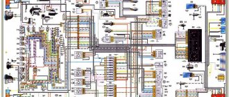
During the operation of the car, problems may arise that can only be solved after studying the electrical circuits. The article presents detailed wiring diagrams for the Lada 4×4 SUV (VAZ 2121), which will help you not only repair the car, but will also be useful when installing additional electrical equipment, for example, a car alarm, DVR and other accessories..
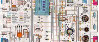
Electrical diagram of VAZ-21213
1 — headlights; 2 — side direction indicators; 3 — electric motor for windshield washer; 4 — headlight washer motor*; 5 - switch; 6 - battery; 7 - starter; 8 - generator; 9 — headlights; 10 — gearmotors for headlight cleaners*; 11 — sound signal; 12 — spark plugs; 13 — carburetor limit switch; 14 — carburetor solenoid valve; 15 — ignition coil; 16 — windshield wiper gearmotor; 17 — carburetor solenoid valve control unit; 18 — ignition distributor sensor; 19 — coolant temperature indicator sensor; 20-oil pressure warning lamp sensor; 21 — plug socket for a portable lamp**; 22 — brake fluid level warning lamp sensor; 23 — windshield wiper relay; 24 — relay for turning on the rear fog light***; 25 — relay for turning on the heated rear window; 26 — relay for turning on headlight cleaners and washer*; 27 — relay for turning on low beam headlights; 28 — relay for turning on the high beam headlights; 29 — ignition relay; 30 — starter activation relay; 31 — relay-breaker for alarm and direction indicators; 32 — heater electric motor; 33 — additional resistor of the heater electric motor; 34 — backlight lamps for heater control levers; 35 — external lighting switch; 36 — main fuse block; 37 — additional fuse block; 38 — reverse light switch; 39 — brake light switch; 40 — instrument lighting regulator; 41 — ignition switch; 42 — three-lever switch; 43 — alarm switch; 44 — tailgate glass cleaner and washer switch*; 45 — heater motor switch; 46 — switch for heating the rear door glass; 47 — rear fog light switch; 48 — lamp switches located in the door pillars; 49 — interior lamps; 50 - cigarette lighter; 51 — switch for the warning lamp for covering the carburetor air damper; 52 — control lamp for covering the carburetor air damper; 53 - switch for differential lock warning lamp; 54 — parking brake warning lamp switch; 55 — sensor for level indicator and fuel reserve; 56 — instrument cluster; 57 — tailgate glass washer motor; 58 — rear lights; 59 — block for connecting additional brake lights; 60 — blocks for connecting side marker indicators; 61 — pads for connecting to the heated glass element of the tailgate; 62 — license plate lights; 63 — gear motor for tailgate glass cleaner.
The order of conditional numbering of plugs in the blocks : a - windshield wipers, headlights and tailgate glass, windshield wiper relay breaker; b — ignition distributor sensor; c — relay-interrupter for alarm and direction indicators; g - switch; d — three-lever switch; e — alarm switch; g — relay for turning on the rear fog light; h — rear lights (numbering of terminals in order from top to bottom); and — instrument clusters.
In the instrument panel wiring harness, the second ends of the white wires are brought together to one point, which is connected to the instrument lighting control. The second ends of the black wires are also brought together to a point connected to ground. The second ends of the yellow wires with a blue stripe are brought together to a point connected to terminal “A” of the main fuse block. And the second ends of the orange wires are also brought together to a point connected to terminal “B” of the main fuse block.
* Installed on parts of manufactured cars; **not installed since 2000; *** installed since 2001. Previously, the rear fog light was switched on directly by switch 47, powered by fuse 3 of the additional fuse box.
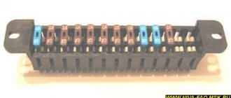
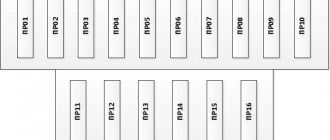
Fuses used in the electrical circuit of the Niva 2121 car
Fuses are used to protect almost all electrical circuits in the system.
In the event of a short circuit, they instantly burn out and open the connection, turning off the protected equipment.
The use of fuses on the Niva 2121 car has a number of its own features:
- All electric motors of the gearmotors that control the windshield wipers are reliably protected by fusible inserts that can be reused. They are of the bimetallic type and operate fully automatically;
- to minimize the risk of a short circuit in the equipment circuit, fuses with a wire with a cross-section of 1 mm are used to supply power to the fuel injection system. Such inserts burn out instantly, opening the network and completely eliminating spontaneous combustion;
- circuits of equipment such as a battery, ignition and engine starting systems, and a generator do not need protection, so fuses are not integrated into them at all;
- the power supply system to the electric cooling radiator fan is protected by an insert that can withstand current and more amperes;
- the electric fuel pump, optical equipment, electric fan motor and other high-power consumers are connected to the on-board network through a special relay equipped with its own fuse and do not require any additional protection;
- 15 amp fuses are installed to protect the electrical circuits of the electronic control unit, fuel pump and main relay of the fuel injection system.
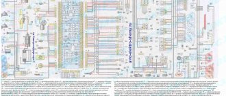
Electrical diagram of VAZ-2121
1 — headlights; 2 — side direction indicators; 3 — headlight washer motor*; 4 - voltage regulator; 5 — battery charge warning lamp relay; 6 - battery; 7 - starter; 8 - generator; 9 — headlights; 10 — gearmotors for headlight cleaners*; 11 — sound signals; 12-spark plugs; 13 — carburetor solenoid valve; 14 — ignition coil; 15 — windshield wiper gearmotor; 16 — coolant temperature indicator sensor; 17 — ignition distributor; 18 — windshield washer electric motor; 19 — oil pressure indicator sensor; 20 — oil pressure warning lamp sensor; 21 — brake fluid level warning lamp sensor; 22 — plug socket for a portable lamp; 23 — relay for turning on headlight cleaners and washer*; 24 — relay for turning on low beam headlights; 25 — relay for turning on the high beam headlights; 26 — windshield wiper relay; 27 — additional fuse block; 28 — main fuse block; 29 — additional resistor of the heater electric motor; 30 — reverse light switch; 31 — brake light switch; 32 — heater electric motor; 33 — relay-interrupter for alarm and direction indicators; 34 — parking brake warning lamp switch; 35 — alarm switch**; 36 — cigarette lighter; 37 — switch for cleaners and headlight washers*; 38 — heater motor switch; 39- external lighting switch; 40 — three-lever switch; 41 — ignition switch; 42 — instrument lighting switch; 43 — lamp switches located in the door pillars; 44 — interior lamps; 45 — oil pressure gauge with insufficient pressure warning lamp; 46 — fuel level indicator with reserve warning lamp; 47 — tachometer; 48 — parking brake warning lamp; 49 — battery charge indicator lamp; 50 — control lamp for the carburetor air damper; 51 — side light indicator lamp; 52 — turn signal indicator lamp; 53 — control lamp for high beam headlights; 54 — speedometer; 55 — carburetor air damper warning lamp switch; 56 — relay-interrupter for the parking brake warning lamp; 57 — coolant temperature indicator; 58 — brake fluid level warning lamp; 59 — differential lock warning lamp; 60 - switch for differential lock warning lamp; 61 — rear lights; 62 — license plate lights; 63-sensor for level indicator and fuel reserve.
The order of conditional numbering of plugs in the blocks : a - windshield and headlight wipers, windshield wiper relay breaker; b — relay-interrupter for alarm and direction indicators; c — three-lever switch; d — hazard warning switch.
* Installed on parts of manufactured cars; ** on cars produced in the 90s, due to the installation of breaker relays 33 without the fifth terminal, the brown wire connecting switch 35 to breaker relay 33 is missing.
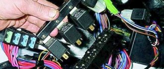
Fuse location
All fusible links used in the electrical circuit of the Niva 2121 car are divided into two groups.
They are located in the fuse boxes located under the dashboard to the right of the driver's seat. You can easily find a description of each of these safety devices, as well as their technical characteristics, in your vehicle's owner's manual. If any electrical equipment in your car has failed, the first thing you need to do is check that the fuse is working properly. To do this, it is very important to follow the following safety rules:
- Before replacing the fuse link, it is necessary to identify and eliminate the cause of its failure;
- In no case should you install fuses that do not meet the requirements of the car manufacturer;
- It is strictly forbidden to close the contacts of the inserts with any metal objects;
- Do not remove fuses from the block using a screwdriver or knife without first turning off the power supply.
In the figure below you can see a detailed diagram of the location of the fuses of the Niva 2121 car, as well as the connections of all electrical equipment.
Engine control system VAZ-21214
Connection diagram of the VAZ-21214 engine management system with central fuel injection under US-83 toxicity standards with controller 21214-1411010 (EFI-4 type) on VAZ-21214 vehicles : 1 - “CHECK ENGINE” control lamp; 2 — instrument cluster (fragments); 3 — electric fans of the engine cooling system*; 4 — electric heater of the intake pipe; 5 — air temperature sensor; 6 — absolute pressure sensor; 7 — coolant temperature sensor; 8 — block connected to the throttle position sensor; 9 — central fuel injection unit; 10 — block connected to the idle speed regulator; 11 — block connected to the nozzle; 12 — diagnostic block; 13 - controller; 14 — knock sensor; 15 — speed sensor; 16 — oxygen concentration sensor; 17 - adsorber; 18 — battery; 19 - main relay; 20 — fuse block of the engine control system; 21 — relay for turning on the electric fuel pump; 22 — relay for turning on the electric fan*; 23 — relay for turning on the electric heater of the inlet pipe; 24 — electric heater protection fuse; 25 — starter activation relay; 26 — ignition relay; 27 — main car fuse box (fragment); 28 — spark plugs; 29 — tachometer; 30 — electric fuel pump with fuel level sensor; 31 — ignition module; 32 — crankshaft position sensor; 33 - courtesy light switch, located on the driver's door pillar; 34 — control unit of the automobile anti-theft system**; 35 — status indicator of the car anti-theft system**; A - wire going to plug “50” of the ignition switch; B - wire going to plug “15” of the ignition switch; B - wire going to terminal “30” of the generator; G - rear wiring harness wires connected to the fuel level indicator; D - rear wiring harness wire connected to switch 33.
The order of conditional numbering of plugs in blocks : a - controller; b — control unit of the automobile anti-theft system; c — indicator of the state of the automobile anti-theft system; g — speed sensor; d — central fuel injection unit; e — electric fuel pump and oxygen concentration sensor; g — ignition module; h - absolute pressure sensor.
Connection diagram of the VAZ-21214 engine management system with distributed fuel injection under Euro-2 toxicity standards with controller 2123-1411020-10 (type MP 7.0) on VAZ-21214 vehicles : 1 - control lamp of the engine management system; 2 — instrument cluster (fragments); 3 — electric fans of the engine cooling system; 4 — courtesy light switch, located on the driver’s door pillar; 5 — status indicator of the car anti-theft system; 6 — control unit of the automobile anti-theft system; 7-coolant temperature sensor; 8 — air flow sensor; 9 — throttle assembly; 10 — block connected to the throttle position sensor; 11 — block connected to the idle speed regulator; 12 - controller; 13 — oxygen concentration sensor; 14 — knock sensor; 15 — crankshaft position sensor; 16 — speed sensor; 17 - adsorber; 18 — battery; 19 - main relay; 20 — diagnostic block; 21 — fuse block of the engine control system; 22 — relay for turning on the electric fuel pump; 23 — relay for turning on electric fans; 24 — main car fuse box (fragment); 25 — block connected to the additional wiring harness*; 26 — ignition module; 27 - tachometer; 28 — electric fuel pump with fuel level sensor; 29 — nozzles; 30 — spark plugs; A - rear wiring harness wire connected to switch 4; B - wires connected to plug “1” of fuse block 24 (one wire goes to plug “15” of the ignition switch, and the other to plug “85” of the ignition relay); B - rear wiring harness wires connected to the fuel level indicator.
The order of conditional numbering of plugs in blocks : a - controller; b — control unit of the automobile anti-theft system; in - air flow sensor; g — speed sensor; d — indicator of the state of the automobile anti-theft system; e — electric fuel pump and oxygen concentration sensor; g - throttle pipe; h — ignition module.
Electrical connection diagram of the EURO-4 ME17.9.7 ECM for cars of the LADA 4x4 family with engine 21214
:
1 – controller; 2 – diagnostic block; 3 – mass air flow sensor; 4 – coolant temperature sensor; 5 – phase sensor; 6 – electric fuel pump module; 7 – pads for the instrument panel harness and rear harness; 8 – ignition coils; 9 – spark plugs; 10 – electronic accelerator pedal; 11 – throttle pipe with electric drive; 12 – electric fan of the engine cooling system, right; 13 – electric fan of the engine cooling system, left; 14 – knock sensor; 15 – pads for the ignition system harness and injector harness; 16 – nozzles; 17 – solenoid valve for purge of the adsorber; 18 – control oxygen sensor; 19 – diagnostic oxygen sensor; 20 – crankshaft position sensor; 21 – APS control unit; 22 – APS status indicator; 23 – ECM fuse block; 24 – fuse for the power supply circuit of the electric fuel pump; 25 – electric fuel pump relay; 26 – left engine cooling system electric fan relay; 27 – relay for the electric fan of the right engine cooling system; 28 – ignition relay; 29 – pads for the ignition system harness and instrument panel harness; 30 – instrument cluster; 31 – vehicle speed sensor; 32 – brake signal switch; 33 – clutch pedal position signal switch; 34 – main fuse block; 35 – additional relay; 36 – contacts of the instrument panel harness pads and the front harness; 37 – contacts of the instrument panel harness and rear harness pads
Download all schemes in high quality To download files you need to log in to the site
turbomotor412 posted a number of diagrams in his BZ:
Let us remind you that you will find detailed instructions for repairing the Lada 4×4 SUV in this section.
0 0 0 0 0 0
Share on social networks:
Maintenance Tips
The factory instructions require troubleshooting the ignition system in the following sequence:
Ignition system: wiring for Niva 21213
- From the ignition switch (terminal 15), connect the wire to the coil (terminal +B) to a test lamp;
- Connect its negative terminal to ground;
- Turn on the ignition - turn the key in the lock to position “II”;
- If the control lamp lights up, then the circuit is working. If not, look for damage to the wire;
- With the ignition on, pull out the central wire from the coil from the distributor;
- Bring its metal tip to the cylinder block so that a gap of 3-4 mm forms between them;
- Turn on the starter for a few seconds;
- If the spark jumps, the coil is working.
Tip: you can quickly check the switch in one way - take it from a working car. If the car starts with the new switch, then you need to buy a new one.
Summarizing
The need to understand the wiring diagram may arise if there are malfunctions in the operation of the system and they need to be eliminated. Of course, complex malfunctions associated with the operation of the generator unit and other devices that are not simple in terms of design will be problematic to solve in a garage without certain knowledge. However, even simple knowledge of the electrical circuit and the ability to decipher the symbols can greatly help the car enthusiast during repairs. In addition, the need to understand wiring may also arise if you decide to upgrade your speakers or install a more advanced audio system.
Features of electrical equipment
The standard wiring on the VAZ 21213 differed from the circuit used on the VAZ 2121. In particular:
- The fuse box on the VAZ 21213 uses more modern “knife” fuses, for which the contact pad is modified;
- The power system uses EPHH - forced idle economizer, for which there is a separate harness with a block in the engine compartment wiring;
- The ignition system uses a non-contact circuit built on a microcontroller.
Differences in the engine compartment
The EPHH control unit is located in the engine compartment and is a plastic box with a connector for connecting a wiring harness to it. Its purpose is to ensure stable engine operation when coasting, including fuel economy.
Self-diagnosis capability
To make it easier to determine engine failure, car owners use a search algorithm based on the car manufacturer’s recommendations.
The manufacturer recommends using it first, and only then resorting to the help of another car:
- Use of known good parts;
- Easy start (“lighting up”), etc.
Conclusions: self-service of a car has long become the norm for our car owners. Moreover, video manuals with explanations of the work have become more accessible today, allowing you to avoid mistakes when troubleshooting the electrical network.
Dashboard
For subsequent modifications of the VAZ 2121, the instrument panel was thoroughly redesigned. In particular, the design and location of the warning lamps have changed, and new scales have appeared on the instrument panel indicators.
Conclusions: the owners of the VAZ 2121 car often serviced it themselves. And servicing electrical systems is impossible without original circuit diagrams. This was especially true for modernized versions, where changes were made to the operation scheme of components and assemblies.