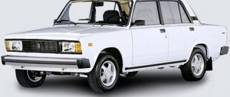
The VAZ 2104 with rear-wheel drive and a station wagon body was produced from 1983 to 2012. The model was constantly improved: electrical equipment was changed, a fuel injection system, a five-speed gearbox and semi-sports front seats appeared. The VAZ 21043 modification was supplemented with a system for cleaning and heating the rear door window. Information on the diagrams is intended for self-repair of cars. Electrical circuits are divided into several blocks for ease of viewing via a computer or phone; there are also files in the form of a single picture with a description of each element - for printing on a printer.
VAZ-2104 diagram (old version)
- block headlights;
- – side direction indicators;
- - accumulator battery;
- – starter enable relay;
- – carburetor electro-pneumatic valve;
- – carburetor microswitch;
- – generator 37.3701;
- – gearmotors for headlight cleaners;
- – electric motor of the engine cooling system fan*;
- – fan motor activation sensor*;
- – sound signals;
- – ignition distributor;
- - spark plug;
- – starter;
- – coolant temperature indicator sensor;
- – engine compartment lamp;
- – oil pressure warning lamp sensor;
- - ignition coil;
- – brake fluid level sensor;
- – windshield wiper gearmotor;
- – carburetor electro-pneumatic valve control unit;
- – electric motor of the headlight washer pump;
- – electric motor of the windshield washer pump;
- – brake light switch;
- – windshield wiper relay;
- – instrument lighting regulator;
- – relay-breaker for alarm and direction indicators;
- – reverse light switch;
- – plug socket for a portable lamp*;
- – cigarette lighter;
- – glove box lighting lamp;
- – mounting block;
- – lamp switches on the front door pillars;
- – lamp switches on the rear door pillars;
- – lampshades;
- – parking brake warning lamp switch;
- – switch for the carburetor air damper warning lamp;
- – tailgate glass cleaner and washer switch;
- – hazard warning switch;
- – three-lever switch;
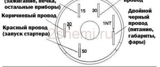
- – ignition switch;
- – ignition relay;
- – external lighting switch;
- – rear fog light switch;
- – fog light circuit fuse;
- – oil pressure warning lamp;
- – instrument cluster;
- – fuel reserve warning lamp;
- – fuel level indicator;
- – courtesy light for the rear part of the cabin;
- – battery charge indicator lamp;
- – coolant temperature indicator;
- – carburetor air damper warning lamp;
- – parking brake warning lamp**;
- – control lamp block;
- – rear fog light indicator lamp;
- – control lamp for heated rear door glass;
- – brake fluid level warning lamp;
- – voltmeter;
- – speedometer 2104;
- – control lamp for external lighting;
- – indicator lamp for direction indicators;
- – high beam warning lamp;
- – heater fan switch;
- – switch for heated rear door glass with backlight;
- – heater fan electric motor;
- – additional resistor for the heater electric motor;
- – electric motor of the tailgate glass washer pump;
- – rear lights;
- – gearmotor for tailgate glass wiper;
- – pads for connecting to the rear glass heating element;
- – license plate lights;
- – sensor for level indicator and fuel reserve.
A
– headlight units, headlight and tailgate glass cleaners, windshield wiper relay breaker, carburetor electric pneumatic valve control unit;
b
– mounting block and three-lever switch;
c
– rear lights (pin numbering in order from top to bottom);
d
– alarm relay and direction indicators.
Main components
But everything is in order. The electrical circuit of the VAZ-2104 (carburetor) is single-wire, that is, all electrical devices are connected to each other by only one wire - “positive”. The role of the negative one is played by the car body and metal components (power plant, transmission).
All devices included in electrical equipment can be divided into several components:
- Working equipment (with the help of which the start and operation of the power plant is ensured);
- Light and sound alarm;
- Auxiliary equipment (facilitating the operation of the car);
- Comfort devices;
Operating equipment includes the battery, starter, generator, elements of the ignition system, as well as devices that control these parts.
At the same time, the battery can be attributed to almost all components, since it provides power to all the car’s devices until the engine is started.
Related link:
Repair of a VAZ-2105 car gearbox
But its main task is to provide power to the starter - the power electric motor with which the engine is started, as well as the ignition system. After the engine is started, the functions of the battery are taken over by the generator, that is, it generates energy that powers all devices. Its task is also to restore the charge expended by the battery when starting the engine. Moreover, in the case of heavy load (many electrical appliances are turned on), when the generator can no longer fully power the equipment involved, the battery begins to feed the network so that the excessive load does not damage the generator.
The ignition system creates a spark charge in the engine cylinders, as a result of which the air-fuel mixture ignites. It includes an ignition coil, a distributor (distributor), spark plugs, and high-voltage wires.
The main control element of the working equipment is the ignition switch, through which electricity is directed to the necessary working devices (ignition system, starter).
Light and sound alarms provide illumination of the roadway in the dark (high and low beam headlights), inform other road users about maneuvers performed by the driver (turning, overtaking, braking, reversing), as well as information about the dimensions of the car (side lights). This also includes the horn and interior lamps. All lighting devices are powered from the battery (while the engine is not running) and the generator (while the engine is running).
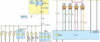
Electrical diagram of VAZ 2104
Scheme of VAZ-2104, for cars of early years of production. It is distinguished from the standard circuit by the G-222 generator, 10-pin hazard warning switch, 5-pin relay for direction indicators and hazard warning lights, top dead center sensor of the 1st cylinder, diagnostic block, rear window heating indicator lamp directly in the switch , the absence of a carburetor choke warning lamp, a two-position exterior lighting switch and a three-position steering column light switch.
1 – headlights; 2 – side direction indicators; 3 – battery; 4 – battery charge warning lamp relay; 5 – carburetor electro-pneumatic valve; 6 – top dead center sensor of the 1st cylinder; 7 – carburetor microswitch; 8 – generator G-222; 9 – gearmotors for headlight cleaners*; 10 – electric motor of the engine cooling system fan*; 11 – fan motor activation sensor*; 12 – sound signals; 13 – ignition distributor; 14 – spark plugs; 15 – starter; 16 – coolant temperature indicator sensor; 17 – engine compartment lamp; 18 – oil pressure warning lamp sensor; 19 – ignition coil; 20 – brake fluid level sensor; 21 – windshield wiper gearmotor; 22 – carburetor electro-pneumatic valve control unit; 23 – electric motor of the headlight washer pump*; 24 – electric motor of the windshield washer pump; 25 – diagnostic block; 26 – brake light switch; 27 – windshield wiper relay; 28 – relay-breaker for alarm and direction indicators; 29 – reverse light switch; 30 – plug socket for a portable lamp; 31 – cigarette lighter; 32 – glove box lighting lamp; 33 – mounting block (a jumper is installed instead of a short-circuit relay); 34 – lamp switches on the front door pillars; 35 – lamp switches on the rear door pillars; 36 – lampshades of VAZ 2104; 37 – parking brake warning lamp switch; 38 – rear window cleaner and washer switch*; 39 – alarm switch; 40 – three-lever switch; 41 – ignition switch; 42 – instrument lighting switch; 43 – external lighting switch; 44 – rear fog light switch; 45 – oil pressure warning lamp; 46 – instrument cluster; 47 – fuel reserve warning lamp; 48 – fuel level indicator; 49 – courtesy light for the rear part of the cabin; 50 – battery charge indicator lamp; 51 – coolant temperature indicator; 52 – relay-interrupter for the parking brake warning lamp; 53 – control lamp block; 54 – brake fluid level warning lamp; 55 – rear fog light indicator lamp; 56 – parking brake warning lamp; 57 – voltmeter; 58 – speedometer; 59 – indicator lamp for external lighting; 60 – turn signal indicator lamp; 61 – control lamp for high beam headlights; 62 – heater fan switch; 63 – switch for heated rear window with control lamp*; 64 – heater fan electric motor; 65 – additional resistor of the heater electric motor; 66 – electric motor of the rear window washer pump; 67 – rear lights; 68 – rear window wiper gear motor*; 69 – pads for connecting to the rear window heating element; 70 – license plate lights; 71 – sensor for level indicator and fuel reserve.
Electrical diagram - full view:
Instructions for diagnosing and replacing electrical wiring
The task of a car's electrical wiring is to ensure high-quality transmission of electric current to all consumers included in the electrical circuit. If any device or component does not work, before changing it, it is necessary to test the electrical wiring that connects it to the power source and other components of the electrical network.
To check the electrical network you need to prepare:
- Multimeter.
- 12V test light with two wires.
Photo gallery
If you have problems with electrical appliances, you should do the following:
- Check voltage. To do this, the multimeter must be switched to voltage meter mode. One probe of the device must be connected to the mass, the role of which is played by the body. We connect the second to the power cord, having previously removed it from the device or instrument. If the tester shows the presence of voltage, then everything is in order. If there is no voltage, the source of the malfunction is located on the section of the circuit being tested.
- Short circuit. In this case, there is completely no voltage in the network. To check the mounting block, you need to remove the fuse and switch the tester into voltmeter mode. One probe must be connected to the terminals in the fuse socket. In this case, all devices included in the tested section of the network must be de-energized. If the numbers on the device jump when you move the wire, it means the wire is shorted.
- Grounding. Since VAZ cars mainly use a single-wire wiring diagram, it is necessary to check the quality of the grounding, since the body is used as a minus for electrical equipment. During operation, metal parts of the body oxidize, become rusty, and their fastening becomes loose. In this case, electrical contact is lost and electrical appliances operate intermittently.
Grounding testing is carried out according to the following algorithm:
- Remove the negative terminal from the battery. Connect one multimeter probe to the car body.
- The second probe is connected to the connection or ground point being tested.
- When values appear on the device, they should be checked against the recommended factory parameters. If the values match, then the grounding is OK.
Checking circuit integrity. This test is necessary to find open circuits.
The verification procedure is as follows:
- The section of the circuit being tested is de-energized: the negative terminal on the battery is disconnected or the corresponding fuse is removed.
- To test the circuit, the multimeter wires are connected to its ends, and one of the probes is connected to ground.
- If numbers appear on the display, this indicates the integrity of the circuit. If nothing appears on the screen, then there is a break in the circuit.
When replacing electrical wiring, use standard wiring or homemade wiring using elements from the standard one. You can use wiring from another car if it meets its specifications.
To replace the wiring, you need to disassemble the front part of the car. If the length of the wires is not enough, they should be increased. All connections must be well insulated. It is better to connect the wires by soldering. It is not advisable to twist the ends of the wires.
Scheme of VAZ-21043 and VAZ-21047 carburetor
1 – headlights; 2 – side direction indicators; 3 – battery; 4 – starter activation relay; 5 – carburetor electro-pneumatic valve; 6 – carburetor microswitch; 7 – generator 37.3701; 8 – gearmotors for headlight cleaners*; 9 – electric motor of the engine cooling system fan; 10 – fan motor activation sensor; 11 – sound signals; 12 – ignition distributor; 13 – spark plugs; 14 – starter VAZ 21047; 15 – coolant temperature indicator sensor; 16 – engine compartment lamp; 17 – low oil pressure indicator sensor; 18 – ignition coil; 19 – low brake fluid level indicator sensor; 20 – windshield wiper gearmotor; 21 – carburetor electro-pneumatic valve control unit; 22 – electric motor of the headlight washer pump*; 23 – electric motor of the windshield washer pump; 24 – reverse light switch; 25 – brake signal switch; 26 – hazard warning and direction indicator relay; 27 – windshield wiper relay; 28 – mounting block; 29 – lamp switches on the front door pillars; 30 – lamp switches on the rear door pillars; 31 – diode for checking the serviceability of the warning lamp for insufficient brake fluid level; 32 – lampshades; 33 – parking brake warning switch; 34 – indicator lamp for insufficient brake fluid level; 35 – signaling unit; 36 – plug socket for a portable lamp**; 37 – glove box lighting lamp; 38 – tailgate glass cleaner and washer switch; 39 – alarm switch; 40 – three-lever switch; 41 – ignition switch; 42 – ignition relay; 43 – econometrician; 44 – instrument cluster; 45 – carburetor air damper closed indicator switch; 46 – battery charge indicator lamp; 47 – indicator lamp for closing the carburetor air damper; 48 – indicator lamp for turning on the direction indicators; 49 – speedometer; 50 – fuel reserve indicator lamp; 51 – fuel level indicator; 52 – instrument lighting regulator; 53 – hours; 54 – cigarette lighter; 55 – fog light circuit fuse; 56 – heater fan electric motor; 57 – additional resistor of the heater electric motor; 58 – electric motor of the tailgate glass washer pump; 59 – rear fog light switch with on indicator; 60 – heater fan switch; 61 – switch for heating the glass of the tailgate with a switch on indicator; 62-external lighting switch; 63 – voltmeter; 64-lamp indicator for turning on external lighting; 65-lamp for high beam headlights; 66 – indicator lamp for insufficient oil pressure; 67 – parking brake indicator lamp; 68 – tachometer; 69 – coolant temperature indicator; 70 – rear lights; 71 – pads for connecting to the heated glass element of the tailgate; 72 – sensor for level indicator and fuel reserve; 73 – courtesy light for the rear part of the cabin; 74 – license plate lights; 75 – rear door glass wiper motor.
Useful: VAZ-2101 diagram
Electrical diagram - full view:
Instructions for diagnosing and replacing electrical wiring
The task of a car's electrical wiring is to ensure high-quality transmission of electric current to all consumers included in the electrical circuit. If any device or component does not work, before changing it, it is necessary to test the electrical wiring that connects it to the power source and other components of the electrical network.
To check the electrical network you need to prepare:
- Multimeter.
- 12V test light with two wires.
Photo gallery
If you have problems with electrical appliances, you should do the following:
- Check voltage. To do this, the multimeter must be switched to voltage meter mode. One probe of the device must be connected to the mass, the role of which is played by the body. We connect the second to the power cord, having previously removed it from the device or instrument. If the tester shows the presence of voltage, then everything is in order. If there is no voltage, the source of the malfunction is located on the section of the circuit being tested.
- Short circuit. In this case, there is completely no voltage in the network. To check the mounting block, you need to remove the fuse and switch the tester into voltmeter mode. One probe must be connected to the terminals in the fuse socket. In this case, all devices included in the tested section of the network must be de-energized. If the numbers on the device jump when you move the wire, it means the wire is shorted.
- Grounding. Since VAZ cars mainly use a single-wire wiring diagram, it is necessary to check the quality of the grounding, since the body is used as a minus for electrical equipment. During operation, metal parts of the body oxidize, become rusty, and their fastening becomes loose. In this case, electrical contact is lost and electrical appliances operate intermittently.
Grounding testing is carried out according to the following algorithm:
- Remove the negative terminal from the battery. Connect one multimeter probe to the car body.
- The second probe is connected to the connection or ground point being tested.
- When values appear on the device, they should be checked against the recommended factory parameters. If the values match, then the grounding is OK.
Checking circuit integrity. This test is necessary to find open circuits.
The verification procedure is as follows:
- The section of the circuit being tested is de-energized: the negative terminal on the battery is disconnected or the corresponding fuse is removed.
- To test the circuit, the multimeter wires are connected to its ends, and one of the probes is connected to ground.
- If numbers appear on the display, this indicates the integrity of the circuit. If nothing appears on the screen, then there is a break in the circuit.
When replacing electrical wiring, use standard wiring or homemade wiring using elements from the standard one. You can use wiring from another car if it meets its specifications.
To replace the wiring, you need to disassemble the front part of the car. If the length of the wires is not enough, they should be increased. All connections must be well insulated. It is better to connect the wires by soldering. It is not advisable to twist the ends of the wires.
Scheme for VAZ-2104 injector
1 – electric motor of the engine cooling system fan; 2 – mounting block; 3 – idle speed regulator; 4 – electronic control unit; 5 – octane potentiometer; 6 – spark plugs; 7 – ignition module; 8 – crankshaft position sensor; 9 – electric fuel pump with fuel level sensor; 10 – tachometer; 11 – control lamp “CHECK ENGINE”; 12 – car ignition relay; 13 – speed sensor; 14 – diagnostic block; 15 – nozzle; 16 – adsorber purge valve; 17, 18, 19 – injection system fuses; 20 – ignition relay for the injection system; 21 – relay for turning on the electric fuel pump; 22 – intake pipe electric heater relay; 23 – electric heater of the intake pipe; 24 – intake pipe heater fuse; 25 – oxygen concentration sensor; 26 – coolant temperature sensor; 27 – throttle position sensor; 28 – air temperature sensor; 29 – absolute pressure sensor;
- A – to the “plus” terminal of the battery;
- B – to terminal “15” of the ignition switch;
- P4 – relay for turning on the fan motor.
Symptoms of a problem
You can determine that there are problems with electrical equipment by the following signs:
- Charger. The battery charging light flashes and goes out when the headlights are turned on. Knocks out the jumper in the voltage regulator. When the ignition is turned on, the charging indicator does not light up.
- Movement. Speed spontaneously increases when moving. Jerking when moving at low speed. Unstable idle. Loss of power during acceleration.
- Wiper. The wipers move jerkily. Windshield wipers do not turn on or do not work in rainy weather. The wipers move jerkily.
- Closures Fuse No. 9 burns out after turning on the ignition or at the start of movement. Fuse #1 blows. Fuse No. 7 burns out when the lights are turned on.
- Dashboard. When the power grid is loaded, the devices begin to display incorrect values.
- Start the engine. The starter does not turn or turns weakly.
- Lighting fixtures do not work.
Basic electrical wiring faults: short circuit or break. In the event of a short circuit, fuses, relays, devices burn out, and even a fire is possible. In the event of a break, either some node, system or device, device, etc. fails. You need to be able to understand the wiring diagram of VAZ 2103, 2104 and other models, find and fix faults (video author - MR.BORODA).
Brake system VAZ 2104
- Brake fluid level sensor built into the expansion tank cap;
- Electronic mounting block in the engine compartment with terminal “A” to the generator;
- Ignition relay with negative terminal to ground;
- Ignition switch on the steering column;
- Indicator lamp on the instrument panel indicating low brake fluid level;
- Indicator lamp for activated parking brake.
Electric windows
Some car owners install electric windows on their VAZ 2104.
The connection diagram for Forward electric windows in the front doors of a VAZ 2104 is quite simple
The features of installing such window lifters on a VAZ 2104 are determined by the size and design of the front door windows. Unlike other classic VAZ models, the front doors of the four (like the VAZ 2105 and 2107) do not have rotary windows. Fully lowered front windows take up more space inside the door frame.
Video: installation of Forward window lifters on the front doors of a VAZ 2107
When choosing electric window regulators, you should ensure that there is free space for installing the electric motor and drive mechanism.
Video: installation of “Granat” window lifters on a VAZ 2107
Thus, independent repair of electrical equipment of a VAZ 2104 for an inexperienced car owner is usually limited to replacing fuses, relays and warning lights, as well as searching for broken electrical wiring. It is quite simple to do this, having in front of your eyes the wiring diagrams for electrical appliances.
Engine Fan Circuits
Download
LADA car bodies. Technical requirements for acceptance for repair, repair and release from repair by enterprises of the service and sales network of JSC AVTOVAZ TU 017207.255.00232934-2006, control dimensions of the body, design, diagnostics, design features of VAZ Car bodies general information (Lada 1970-2015) These technical conditions repairs apply to car bodies produced by JSC AVTOVAZ and their components for repair (disassembly and assembly,
Sources
- https://divide.doitwork.ru/skachat-vaz-21043-shema-montazhnogo-bloka.html
- https://camp.provelsk.ru/skachat-vaz-21043-inzhektor-shema-elektrooborudovanija.html
- https://mobiauto.pp.ua/page/2842/
Scheme for switching on headlights and fog lights
1 — block headlights; 2 — mounting block 2104; 3 — headlight switch in a three-lever switch; 4 — external lighting switch; 5 — rear fog light switch; 6 — rear lights; 7 - rear fog light circuit fuse; 8 — fog light indicator lamp, located in the indicator lamp block; 9 — indicator lamp for high beam headlights, located in the speedometer; 10 — ignition switch; P5 - headlight high beam relay; P6 - low beam headlight relay; A - view of the headlight plug connector: 1 - low beam plug; 2 — high beam plug; 3 — ground plug; 4 — side light plug; B - to terminal 30 of the generator; B — terminals of the rear light printed circuit board (numbering of terminals from the edge of the board): 1 — to ground; 2 — to the brake light lamp; 3 — to the side light lamp; 4 — to the fog light lamp; 5 — to the reversing light lamp; 6 - to the turn signal lamp.
Injection motor
If a VAZ is equipped with an injection ignition system, then it is arranged according to the same principle.
Thanks to the installed sensors, the controller collects information and, after processing it, controls the operation of the power unit. A special program (firmware) determines the required amount of fuel for each cylinder so that the engine operates in optimal mode. The injection and spark formation time for each cylinder is determined. Based on the combustion quality of the fuel assembly, the fuel volume and ignition timing are adjusted. On the VAZ 21041 injector, the electrical circuit is similar to the VAZ 2104.
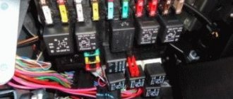
Fuse and relay block VAZ-2104
On newer “sevens” a block with 17 fuses and 6 relays is installed. VAZ 2107 fuses on the “new” unit protect the following electrical circuits and devices:
- Reversing lamps, heater fan, rear window defroster warning lamp and relay, rear wiper motor and rear washer pump.
- Electric motor for front wipers.
- Reserve socket.
- Reserve socket.
- Power supply for heated rear window.
- Clock, cigarette lighter, power socket “carrying”.
- Signal and radiator fan.
- Turn signal lamps in emergency mode.
- “Fog lights” and a relay that regulates the voltage of the on-board network.
- Instrument panel lamps.
- Brake light bulbs.
- Right high beam headlight.
- Left high beam headlight, high beam warning lamp.
- Side lights (rear right, front left), license plate and engine compartment lighting.
- Side lights (rear left, front right), glove compartment and cigarette lighter lamps.
- Low beam (right lamp).
- Low beam (left lamp).
The block relays perform the following functions:
- Heated rear window relay.
- Headlight cleaner and washer relay.
- Signal relay.
- Cooling system electric fan relay.
- High beam relay.
- Low beam relay.
Symptoms of a problem
You can determine that there are problems with electrical equipment by the following signs:
- Charger. The battery charging light flashes and goes out when the headlights are turned on. Knocks out the jumper in the voltage regulator. When the ignition is turned on, the charging indicator does not light up.
- Movement. Speed spontaneously increases when moving. Jerking when moving at low speed. Unstable idle. Loss of power during acceleration.
- Wiper. The wipers move jerkily. Windshield wipers do not turn on or do not work in rainy weather. The wipers move jerkily.
- Closures Fuse No. 9 burns out after turning on the ignition or at the start of movement. Fuse #1 blows. Fuse No. 7 burns out when the lights are turned on.
- Dashboard. When the power grid is loaded, the devices begin to display incorrect values.
- Start the engine. The starter does not turn or turns weakly.
- Lighting fixtures do not work.
Basic electrical wiring faults: short circuit or break. In the event of a short circuit, fuses, relays, devices burn out, and even a fire is possible. In the event of a break, either some node, system or device, device, etc. fails. You need to be able to understand the wiring diagram of VAZ 2103, 2104 and other models, find and fix faults (video author - MR.BORODA).
Car modifications
VAZ-2104 . The basic version of the station wagon, with a carburetor engine from the VAZ-2105, 1.3 liters and 64 horsepower. Equipped with a 4-speed gearbox.
VAZ-21041 . A prototype of a station wagon, it was equipped with a carburetor engine from a VAZ-2101, with a volume of 1.2 liters and a power of 62 hp. Just like the base model, it was equipped with a 4-speed manual transmission.
VAZ-21042 . Export version, the steering wheel was located on the right. The car also received a carburetor engine from the VAZ-2103, with a volume of 1.5 liters and a power of 72 hp.
VAZ-21043 . The car was equipped with electrics and interior from a VAZ-2107, some copies had a VAZ-2106 interior. The carburetor engine was borrowed from the VAZ-2103. The gearbox was either 4 or 5 speed.
VAZ-21044 . An export model, equipped with a 1.7-liter VAZ-2107 engine with mono-injection, as well as a 5-speed gearbox.
VAZ-21045 . The export version with a 1.8-liter engine did not enter mass production.
VAZ-21045D . It was produced in small series since 1999, equipped with a VAZ-341 diesel engine with a volume of 1.52 liters and a power of 50 horsepower. The gearbox is 5-speed.
VAZ-21047 . A prototype with an engine starting from a penny. An improved version of the “Four”, it was equipped with a VAZ-2107 interior and a VAZ-2103 carburetor engine with a volume of 1.5 liters and a power of 72 hp. The gearbox was 5-speed. On export versions, the radiator grille was installed from the VAZ-2107.
VAZ-21048 . Diesel station wagon, with a 1.77-liter VAZ-343 engine. The gearbox is 5-speed.
VAZ-21041i . A car equipped with a VAZ-21067 injection engine. volume 1.6 liters. The gearbox is 5-speed. The electrical equipment and interior are from a VAZ-2107 car, and the front seats are from the Izhevsk hatchback IZH-2126.
VAZ-21041 VF . The interior, electrics and front seats are the same as the previous modification; the radiator grille is also borrowed from the VAZ-2107. It was equipped with a 1.5 liter injection engine from the VAZ-2103 and a 5-speed manual transmission.
Summary
Overall, the car turned out to be of good quality, which allowed it to remain on the factory assembly line until 2012. Among the features of this attractiveness are low price, the possibility of increasing the interior, ease of maintenance and availability of spare parts.
Similar materials
Names such as the Paris-Dakar Rally and Mitsubishi Pajero are inextricably linked. Of course, after all, behind the wheel of this Japanese SUV, different racers won 12 victories.
Many car owners are thinking about how they can tune Dodge Caravan headlights, because now lensed designs of excellent quality are widespread.
The absence of fog lights on a modern car significantly worsens its safety in conditions of poor visibility. On Kalina cars the manufacturer already.
Model 3110 of the Gorky Automobile Plant was launched into production in 1997 and was conceived as a more modern and improved solution, comparable to the configuration.
Carburetor internal combustion engine
Most classic VAZ models with a carburetor are equipped with a KSZ contact ignition system. Since 1987, cars began to be equipped with a contactless ignition system. The engine for the VAZ 2104 was created on the basis of the VAZ 2103 power unit, and accordingly, the VAZ 2103 electrical circuit was used.
Classic ignition
The KSZ includes a distributor (2), a coil (5), spark plugs (1), high-voltage wires, and connecting wires. The system also includes a capacitor (3), a relay (7), a breaker cam (4), a mounting block (6), and a switch (8).
On machines with KSZ, a distributor 30.3706-01 is installed. It is located on the left side of the cylinder block in the front part. Thanks to it, the circuit of the primary winding is interrupted and high voltage is distributed across the spark plugs in the required sequence. The distributor consists of ignition timing regulators, a high-voltage pulse distributor, and a breaker with contacts.
A B-117A with an open magnetic circuit is used as an ignition coil. It is located in the engine compartment and is attached to the left mudguard using two nuts. The device is used to convert low-voltage current into high-voltage current. The installed A17DVR spark plugs serve to ignite the fuel-air mixture in the cylinders of the power unit.
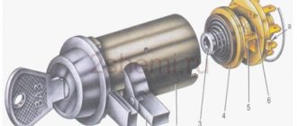
A VK347 type switch is installed, which has an anti-theft device. The anti-theft operating principle: when the key is removed from the lock in the “Parking” position, the locking rod extends, which blocks the steering shaft, entering a special groove.
Electronic ignition
The design of the contactless ignition system includes:
- distributor (distributor);
- sensor;
- switch that controls the system;
- high voltage coil;
- spark plug ;
- connecting and high-voltage wires.
On VAZs with BSZ, a distributor 38.3706-01 is installed, its location coincides with the KSZ distributor. The coil consists of two windings. One is connected to the ignition switch relay, and the second is connected through a high-voltage wire to the distributor.
Using small cross-section wires, the coil and distributor are connected to a switch, which is responsible for the timely supply of a spark. The commutator converts the sensor pulses into a pulse current, which is supplied to the primary winding of the coil. The coil is also located in the engine compartment, like the KSZ coil.
Do not disconnect the wires from the switch if the ignition is on. The switch may be damaged if the battery terminals are removed while the engine is running.
The operating instructions contain an electrical diagram of the VAZ 21043 carburetor with a description of the main components included in it.
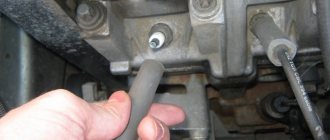
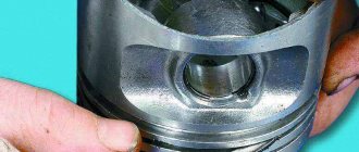
What is the structure of the generator from the inside
You can use a piece of pipe of a suitable size as it. To open the unit, you need to remove the cover by pushing it upward.
To check the regulator, connect a voltmeter or test lamp to the brushes. To charge the battery and normal operation of electrical equipment, the voltage should be 13.8 - 14.2 Volts.
Installation of the generator in place is fixed with a 17 nut and a lower bolt
I had to buy another relay regulator, after which the charge returned to normal values. At the stand Diagnostics at the stand is carried out at the service center, and if everything necessary is available, it can also be done at home. F2 10A Wiper motors. Indicator for turning on side lights.
Total information
The appearance of the VAZ 2104 station wagon on the domestic market was justified by several reasons:
- Firstly, its predecessor, the VAZ 2102, was based on a penny chassis, while the automaker was already mass-producing more modern models (see, for example, VAZ 21213: nuances of operation).
- And secondly, the country needed transport that would allow ordinary citizens to provide themselves with a universal vehicle that could be used to transport simple belongings over long distances.
The video presented in the article clearly demonstrates its capabilities as a multifunctional vehicle capable of not only transporting passengers within the city, but also as a means of active tourism:
- travel to mountainous areas;
- trips to nature;
- long-distance routes to sea coasts, etc.
The model turned out to be popular in the countries of the socialist camp.
It was supplied there from 1984 to 2009 inclusive, and was offered under the trade names:
- Lada Estate,
- Lada Combi or Lada Nova Combi,
- Lada Riva Break.
Export versions have always been distinguished by high-quality painting
Note! The electrical wiring diagram of the VAZ 2104 in the export version was distinguished by the presence of a heated rear window and a windshield wiper on the rear door. Also, similar equipment was found in the VAZ 21043, which borrowed the interior and electrical equipment from the VAZ-2107, and since 1994 it has become standard equipment for all “fours”.
You can read about other differences between AvtoVAZ export models in the article - how much better is the Samara Baltic version than its domestic counterparts.