Work progress
- First you will need to clean the piston head of carbon deposits. The piston must be replaced if there are burrs, burn marks, deep scratches, or cracks on it. Then clean the grooves for the piston rings. It is convenient to perform this operation using a piece of an old ring.
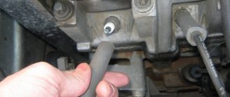
- You should also clean the oil drain holes. Use a suitable piece of wire.
- Check the clearances between the rings and grooves on the piston. Nominal clearance, mm: upper compression ring 1 – 0.04–0.075; lower compression ring 2 – 0.03–0.065; oil scraper ring 3 – 0.02–0.055; The maximum permissible gap for all rings is 0.15 mm.
- The most accurate way to determine clearances is by measuring the rings and grooves on the piston. To do this, measure the thickness of the rings with a micrometer in several places around the circumference, then...
- ...using a set of feeler gauges, measure the width of the grooves in several places around the circumference. Calculate the average clearance values (the difference between the ring thickness and the groove width). If at least one of the gaps exceeds the maximum permissible, replace the piston with rings.
- Measure the gaps in the ring locks by inserting the ring into a special mandrel. If there is no mandrel, insert the ring into the cylinder (in which it worked), use the piston as a mandrel to push the ring into the cylinder so that it is installed evenly in the cylinder, without distortions and...
- ...measure the gap in the ring lock with a feeler gauge. The nominal gap should be 0.25–0.45 mm, the maximum permissible (as a result of wear) is 1.0 mm. If the gap exceeds the maximum permissible, replace the ring.
- If the gap is less than 0.25 mm, carefully file off the ends of the ring with a file.
- Check the clearances between the pistons and cylinders. The clearance is defined as the difference between the measured diameters of the piston and cylinder. The nominal gap is 0.025–0.045 mm, the maximum permissible is 0.15 mm. If the gap does not exceed 0.15 mm, you can select pistons from subsequent classes so that the gap is as close as possible to the nominal one. If the gap exceeds 0.15 mm, bore the cylinders to the next repair size and install pistons of the corresponding repair size. Measure the diameter of the piston at a distance of 55 mm from its bottom in a plane perpendicular to the piston pin.
- Then measure the diameters of the cylinder in two perpendicular planes (along B and across A of the cylinder block) and in four zones (1, 2, 3 and 4). For this you need a special device - a bore gauge.
- When replacing parts of the connecting rod and piston group, it is necessary to select pistons to cylinders by class and one group by weight, as well as piston pins to pistons by class and connecting rods by weight. To select pistons for cylinders, calculate the gap between them. For the convenience of selecting pistons for cylinders, cylinders and pistons, depending on their diameters, are divided into five classes: A, B, C, D, E. Spare parts are supplied with pistons of nominal sizes of three classes A, C, E and two repair sizes. The first repair is increased by 0.4 mm, the second - by 0.8 mm. Based on weight, the pistons are divided into three groups: normal, increased by 5 g and decreased by 5 g. Pistons of the same group must be installed on the engine. For repair size pistons, spare parts include repair size rings increased by 0.4 mm and 0.8 mm. The number “40” is stamped on the rings of the first repair size, and “80” on the second.
- On the cylinder block, a group of cylinders is knocked out on the lower plane of the block (the mating plane under the oil sump) opposite each cylinder.
- The following data is stamped on the bottom of the piston: 1 – piston class based on the pin hole; 2 – piston diameter class; 3 – arrow showing the direction of installation of the piston; 4 – repair size (1st repair – triangle, 2nd repair – square); 5 – weight group (normal – “G”, increased by 5 g – “+”, reduced by 5 g – “-”).
- Replace pins with cracks. The finger should easily enter the piston using the force of the thumb. Insert your finger into the piston. If play is felt when rocking the finger, replace the piston. When replacing a piston, select a pin according to its class. The piston pins are divided by diameter into three classes (1st, 2nd, 3rd) every 0.004 mm. The class of the finger is marked on its end with paint. The piston pin class is stamped on the piston bottom, the connecting rod pin class is stamped on the connecting rod cap.
- Replace broken rings and oil ring expander.
- Replace broken or cracked circlips that hold the piston pin in place. The ends of the retaining rings must be in the same plane. Replace bent rings.
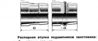
- Replace bent connecting rods. Replace the connecting rod if there are burrs and deep scratches in the bushing 1 of the upper head. Replace the connecting rod if, upon disassembling the engine, it is discovered that the connecting rod bearings have rotated in the connecting rod. The connecting rods are processed together with the covers, so they need to be replaced as a set.
- Insert a pin into the upper end of the connecting rod. If play is felt when rocking the pin, replace the connecting rod. Connecting rods assembled with covers are divided into classes based on the weight of the upper and lower heads.
- The engine must have connecting rods of the same class. The connecting rod is marked on its cover: 1 – connecting rod class by weight (letter or paint), 2 – connecting rod class by pin.
- If there are deep scratches, scratches, nicks on the surfaces on which the oil seals operate, the crankshaft must be replaced.
- Measure the main and connecting rod journals of the crankshaft. Nominal diameters of the crankshaft journals, mm: main – 50.799–50.819; connecting rods - 47.830–47.850. If the wear of the journals exceeds 0.03 mm or the ovality of the journals exceeds 0.03 mm, they need to be ground to the nearest repair size. There are four repair sizes with a reduction in the diameter of the journals: the first - 0.25 mm; second – 0.5 mm; third – 0.75 mm; fourth – 1.00 mm.
- If there are minor scuffs, marks, or scratches on the main and connecting rod journals 1, you need to grind them to the nearest repair size. It is recommended to carry out this work in a specialized workshop. Then polish the journals and blunt the sharp edges of the chamfers of the oil channels 2 with an abrasive cone. Wash the crankshaft and blow out the oil passages with compressed air. The ovality and taper of all journals after grinding should not exceed 0.005 mm. After grinding the journals, install inserts of repair sizes.
- If there are burrs, marks or peeling on the working surfaces of the thrust half-rings, replace the half-rings. It is prohibited to carry out any adjustment work on the half rings.
- Measure the axial clearance of the crankshaft. To do this, install the crankshaft and thrust half-rings into the cylinder block and tighten the bolts securing the main bearing caps.
- Install the indicator so that its leg rests against the shaft flange. Move the crankshaft as far as it will go from the indicator and set the indicator arrow to 0. Move the shaft in the opposite direction. The indicator will show the gap size. The nominal axial clearance of the crankshaft is 0.06–0.26 mm, the maximum permissible is 0.35 mm. If the gap exceeds the maximum permissible, replace the thrust half-rings. Spare parts are supplied with thrust half-rings of two sizes: nominal – 2.31–2.36 mm and repair (increased by 0.127 mm) – 2.437–2.487 mm.
- Inspect the connecting rod and main bearings. If they have cracks, burrs, or chipping, replace the liners. It is prohibited to carry out any adjustment work on the liners. Nominal thickness of liners, mm: main ones – 1.824–1.831; connecting rods - 1.723–1.730. The inserts are supplied in spare parts in four repair sizes, with increased thickness: the first – by 0.25 mm; the second – by 0.5 mm; third – by 0.75 mm; the fourth - by 1.00 mm.
- Check the clearances between the main bearing shells and the crankshaft journals. It is recommended to carry out this work in a specialized workshop. Measure the diameter of the journals and the diameters of the main bearings by installing the caps with liners on the block and tightening them to the appropriate torques. Calculate the gap. The gaps between the liners and the crankshaft journals are equal: main bearings (nominal) - 0.026–0.073 mm, maximum permissible - 0.15 mm; connecting rod bearings (nominal) – 0.02–0.07 mm, maximum permissible – 0.1 mm. If the gap exceeds the maximum permissible, the crankshaft must be ground to the next repair size.
- In a specialized workshop you can measure the runout of the crankshaft journals. The runout should be: main journals and seating surface under the drive gear of the oil pump - no more than 0.03 mm; landing surface for the flywheel – no more than 0.04 mm; seating surface for pulleys and oil seals – no more than 0.05 mm.
- Thoroughly clean and flush the crankshaft oil passages.
- It is not recommended to press out the plugs yourself; to do this, contact a specialized workshop.
- Thoroughly clean the surfaces of the cylinder block from any remaining old gaskets. Inspect the block carefully. If cracks are found, the block must be replaced as an assembly with the main bearing caps.
- Check the tightness of the cylinder block cooling jacket. To do this, plug the hole under the water pump (installing the pump with a gasket) and pour Antifreeze-A40 into the cooling jacket. If there is a noticeable leak in any place, then the unit is leaking and needs to be replaced.
- Inspect the cylinders. If there are scratches, burrs, holes, etc. on the cylinder mirror, bore the cylinders to the repair size (it is recommended to have this work done in a specialized workshop) or replace the cylinder block. For various defects with a depth of more than 0.8 mm, the block cannot be repaired and must be replaced.
- Clean the carbon deposits on the top of the cylinders. If a belt has formed there due to wear on the cylinders, remove it with a scraper. Check the wear of the cylinders by measuring their diameters (see point 10).
Disassembling the 2110 engine
The procedure for assembling the VAZ 2111 engine
Crankshaft pulley
The generator and water pump on the VAZ 2106 are driven by a belt from the crankshaft pulley. When carrying out repair work on the engine, attention should also be paid to the condition of the pulley: is there any visible damage (cracks, scuffs, dents). If defects are found, the part should be replaced.
When repairing an engine, carefully inspect the crankshaft pulley for damage. If defects are found, the part must be replaced
During the installation process, the pulley should sit smoothly on the crankshaft, without distortion. Despite the fact that the pulley fits quite tightly on the shaft, a key is used to prevent rotation, which can also be damaged. A defective part must be replaced.
To protect the crankshaft pulley from turning, a key is used. The part may break over time, which indicates the need to replace it.
Crankshaft marks
In order for the engine to work flawlessly, after installing the crankshaft, the correct ignition setting is necessary. There is a special casting on the crankshaft pulley, and on the cylinder block there are three marks (two short and one long) corresponding to the ignition timing. The first two indicate an angle of 5˚ and 10˚, and the long one - 0˚ (TDC).
There are marks on the crankshaft pulley and on the cylinder block by which the first piston is installed at TDC for correct ignition adjustment
The mark on the crankshaft pulley is located opposite the length of the marks on the cylinder block. There is also a mark on the camshaft sprocket that must be aligned with the casting on the bearing housing. To rotate the crankshaft, use a special wrench of the appropriate size. According to the marked marks, the piston of the first cylinder is at top dead center, while the slider on the ignition distributor must be installed opposite the contact of the first cylinder.
Despite the fact that the crankshaft is a critical component of any engine, even a novice auto mechanic can repair the mechanism, with the exception of the grinding stage. The main thing is to select the elements according to the dimensions of the shaft, and then follow the step-by-step instructions for assembling it.
Technical characteristics of VAZ 2106
Performance characteristics of the VAZ 2106 six Maximum speed: 150 km/h Acceleration time to 100 km/h: 17.5 s Fuel consumption per 100 km in the city: 10.1 l Gas tank volume: 39 l Curb vehicle weight: 1035 kg Permissible gross weight: 1435 kg Tire size: 175/70 SR13
Engine characteristics
Position: front, longitudinal Engine capacity: 1569 cm3 Engine power: 75 hp Number of revolutions: 5400 Torque: 116/3000 N*m Power system: Carburetor Turbocharging: no Gas distribution mechanism: OHC Cylinder arrangement: In-line Number of cylinders: 4 Cylinder diameter: 79 mm Piston stroke: 80 mm Compression ratio: 8.5 Number of valves per cylinder : 2 Recommended fuel: AI-92
Brake system
Front brakes: Disc Rear brakes: Drum
Steering
Steering Type: Worm Gear Power Steering: No
Transmission
Drive: Rear Number of gears: manual gearbox - 4 Gear ratio of the main pair: 4.1
Suspension
Front suspension: Double wishbone Rear suspension: Coil spring
Body
Body type: sedan Number of doors: 4 Number of seats: 5 Vehicle length: 4166 mm Vehicle width: 1611 mm Vehicle height: 1440 mm Wheelbase: 2424 mm Front track: 1365 mm Rear track: 1321 mm Ground clearance (clearance): 170 mm Trunk volume: 345 l
Production
Year of manufacture: from 1976 to 2005
Modifications of VAZ 2106
VAZ-21061 - VAZ-2103 engine with a volume of 1500 cm3. Initially, this index was supposed to denote a special version for Canada, which included being equipped with special bumpers - aluminum, without fangs, with linings and ends made of black plastic.
VAZ-21062 is an export modification of the VAZ-2106 with right-hand drive.
VAZ-21063 is an improved version of the VAZ-21011 engine, with an oil pressure sensor and an electric fan instead of a belt-driven impeller (in a variant, belt drive was allowed).
VAZ-21064 is an export modification of the VAZ-21061 with right-hand drive.
VAZ-21065 is a modernized modification with improved equipment, produced in 1990 - 2001. It differed from the base model by a more powerful generator, a five-speed gearbox, a rear axle gearbox with a gear ratio of 3.9, a contactless ignition system, a Solex carburetor (21053-1107010), halogen headlights, seat upholstery and headrests, as well as a standard rear fog lamp and electrically heated rear window. Equipment 21065-01 was equipped with an engine from model 2103.
VAZ-21066 is an export modification of the VAZ-21063 with right-hand drive.
VAZ-21067 - IzhAvto assemblies. The VAZ-21067 engine, which differs from the base one by the presence of a fuel injection system with a catalytic converter, which ensures compliance with Euro-2 toxicity standards.
VAZ-21068 - was released as a carrier of units during the development period of the new VAZ-2108 and VAZ-21083 engines.
VAZ-21069 - cars were manufactured for special services. Externally, it is completely identical to the VAZ-2106, but with a two-section VAZ-411 RPD with a power of 120 hp. Since 1983, a VAZ-413 engine with a power of 140 hp could be installed, and since 1997, a universal RPD for rear-wheel drive and front-wheel drive VAZ VAZ-415.
VAZ-2106 “Tourist” is a pickup truck with a tent built into the body, created by order of the technical directorate. The project was rejected by the plant's head management, and the only silver copy was repainted red and subsequently used as in-plant technical equipment.
VAZ-2106 “Half past six” is the only copy made according to a special order received from L.I. Brezhnev or someone from his entourage after the demonstration of experienced VAZ-2107 to the top leadership of the USSR in 1979. In addition to export bumpers, it was distinguished by seats and grille radiator from 2107, as well as a hood modified for its installation.
What engine can be installed on a VAZ 2103 instead of the standard one?
Domestic cars are good because with a sufficient budget it will be possible to implement almost any planned project. Even when connecting the engine to the gearbox there are no particular difficulties. Thus, almost any power unit is suitable for the VAZ 2103. The main thing is that it must fit in size.
Rotary engine
Until a certain time, only special police forces and the KGB were armed with cars with such engines. However, tuning enthusiasts in the USSR, folk craftsmen, found and installed a rotary piston engine (RPE) on their VAZ 2103.
The RPD can be easily installed on any VAZ car. It goes to Moskvich and Volga in a three-section version.
The rotary piston engine can be easily installed on any VAZ car
Diesel engine
The diesel engine is mated to the standard VAZ 2103 gearbox using an adapter plate, although the gear ratios of the engines are not at all suitable.
- Driving with a diesel Volkswagen Jetta Mk3 will not be very comfortable, especially after 70–80 km/h.
- The option with a diesel unit from the Ford Sierra is a little better. In this case, you will have to change the design of the tunnel, install a gearbox from a BMW and make some other changes.
Motors from foreign cars
In general, foreign-made engines have been and are often installed on the VAZ 2103. True, it is impossible to avoid additional modifications in this case.
- The most popular engine is the Fiat Argenta 2.0i. About half of the owners of tuned “threes” installed these engines. There are practically no problems with installation, however, the engine is a bit old, which is unlikely to please the owner.
- Engines from BMW M10, M20 or M40 are also suitable. We have to modify the struts, rework the flywheel and replace the axles.
- Engines from Renault Logan and Mitsubishi Galant are praised by craftsmen, but in these cases the gearbox has to be changed.
- And, probably, the best option is the power plant from Volkswagen 2.0i 2E. True, such an engine is not cheap.
How to replace bearings without removing the engine?
Many car owners think and write on forums that it is impossible to get to the liners without removing or removing them from the engine hood. However, such operations are carried out by repairmen on ships, where the size of the parts is enormous and too much force is required to remove the engine. And if the technique exists, it can be used for simple cars.
- Park the vehicle on a ramp to gain easy access to the engine. If there is protection installed on it, it should be removed and the lubricant drained.
- Remove the box, front cover and loosen the camshaft chain in advance. If you're not too lazy, it's better to remove it entirely so it doesn't interfere.
- Remove the starter and pan (if the beam does not interfere). If it interferes with operation, you will have to lift the motor and pull out the pan from under it.
- You now have access to the crankshaft. The easiest way is to replace the connecting rod bearings. The old bearings are pulled out after unscrewing the head screws; it’s easy to put new ones in place, just don’t forget to lubricate them well with the same engine oil that is in your engine.
- It is more difficult to replace the main bearings without removing the engine. You will need to lower the crankshaft by loosening its fastening. You don’t need to lower it much, ten, maximum fifteen centimeters.
- Now it will be easier to pull out the earbuds. But you will need an aluminum rivet, which must be inserted into the lubrication hole, so it will push the bearing out. The main thing is that the size of the rivet is suitable and does not scratch the crankshaft.
When may repair dimensions of crankshafts be required?
First of all, let's look at the different types of defects that occur, as well as the reasons for their occurrence. If the geometry of the seats for the support bearings of the block is broken, rapid wear of the journals should be expected. In other words, if this process is observed, the reason is most likely exactly the same as indicated above, or in the poor quality of the material of the shaft itself. Due to poor-quality oil or its irregular replacement, scuffs may appear on the necks; a clogged oil filter, or, which is even worse, low pressure in the system, can also be the source of this trouble.
Installation of pistons and connecting rods
The next step is to install the pistons on the connecting rods. Pistons and connecting rods have a certain direction in relation to the engine. The arrow on the pistons indicates the forward direction, that is, they should be directed from the flywheel towards the front cover.
There are numbers on the connecting rods; they should face forward in the same way.
Taking this direction into account, we connect the piston and connecting rod using a piston pin. Before installing the pin, the piston must be heated; just place it in hot water for a few minutes. In the piston, the pin is locked on both sides by retaining rings.
What's the result?
Taking into account the above information, we can conclude that the appearance of knocking in the engine is a sign for immediate cessation of operation of the vehicle. It should also be taken into account that the condition of the liners is greatly influenced by the operating temperature of the power unit. In other words, engine overheating can lead to cranking of the connecting rod or main bearings, engine jamming, etc. In this case, the engine may become completely unusable, as the crankshaft bed breaks, the crankshaft itself, the cylinder block, etc. fail.
As for engine oil, it is necessary to use only those fuels and lubricants that meet all the requirements and necessary approvals of the power unit manufacturer. Also, the oil and oil filter must be changed promptly to prevent dirt and mechanical particles from getting into the lubricant. The lubrication system itself also deserves increased attention, since decreased performance or malfunctions can lead to oil starvation, which significantly increases the risk of bearings turning.
Finally, we add that the gasoline engine needs to be warmed up after a cold start, then you need to drive without loads until the power plant reaches operating temperatures. In the case of a diesel engine, the engine warms up while driving; it is not recommended to sharply load the unit until it is completely warmed up. It should also be remembered that both a new engine and a motor after repair need to be run in, since loaded pairs and mating elements need to be ground in.
Crankshaft repair
Grinding of the crankshaft is performed on a rotating emery wheel. During operation, the shaft is rotated around the base axes of either the main or connecting rod journals. It is also necessary to ensure that the center-to-center condition is maintained and to be extremely careful about maintaining the shape of the fillets, otherwise repairs can only accelerate the destruction of the crankshaft.
After grinding, the shaft and flywheel assembly must be dynamically balanced to avoid vibration in the rebuilt engine. However, in practice this condition is rarely met, especially during individual repairs.
In some cases, it is impossible to repair damage to the journals by grinding. Then you can consider the option of surfacing or spraying (including plasma) followed by grinding to zero (nominal) size. Depending on the material being deposited, the strength of the journal may even increase compared to factory values. At the final stage of processing, the journals are polished and finished to achieve the optimal degree of roughness.
It is important to take into account that the sizes of necks of the same type must necessarily match. Different types may have different diameters
For example, the main ones can be of the second repair size, and the connecting rods can be of the third. The exception is situations of field repair, in which the journals may not have a standard repair size at all.
It should also be noted that the specific loads placed on the crankshaft often cause its failure. Most often this happens due to an increase in gaps with the liner, which entails deterioration of lubrication. A broken crankshaft cannot be repaired and must be replaced.
Is it possible to tune the Priora 126 engine?
Even with a strong desire, the 126 engine will not be able to reach a speed of 100 km/h in a few seconds. Without tuning the Lada Priora engine, overtaking prestigious brands will also not be possible.
According to many motorists, it is necessary to install a turbocharger from the very beginning. In this case, the engine power will increase by no more than 15 - 20%. Special filter elements are additionally installed here to clean the cold air as it enters the engine.
The main improvements to the 21126 motor are:
- cylinder boring;
- increase in piston stroke.
With the help of these modifications, it is possible to most effectively boost the 126 engine, the power of which increases by 50 horsepower. The main purpose of boring is to increase the volume of the cylinders. The process comes down to primitive actions:
- cylinder walls are reduced in thickness;
- more gasoline is burned in the resulting volume;
- engine performance increases;
- power increases.
When choosing a future car, we definitely pay attention to what kind of power unit (heart) it has. Not only the dynamics depend on the motor, but also how much money is required for its maintenance
Do you know which modern VAZ engine to choose?