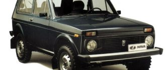
The relatively low-cost model of domestic production is extremely common among motorists in the CIS countries due to the low cost and sufficient cross-country ability of the crossover. The lightweight SUV stands out among its peers due to its combination of performance and minimal price.
A separate topic of conversation is the reliability of the car. Electronic components and assemblies of a machine often fail due to insufficient reliability of electronic components. The circumstance gives rise to questions among car enthusiasts about what the pinout of a Chevrolet Niva looks like and how its design can be repaired.
Electrical wiring components
The standard Niva Chevrolet wiring diagram is divided into several sections for better maintainability and ease of maintenance.
- Front part - a set of cables connects all equipment located in the engine compartment of the car.
- The interior part - the unit is additionally divided into independent zones, which allows you to power different groups of equipment without the risk of damaging or overloading the main elements.
- Instrument panel compartment - a bundle of cables combines the lines from all gauges, sensors and indicators.
- The stern assembly - the bundle is responsible for voltage and control of equipment located on the rear side of the vehicle.
About the main elements of an electrical circuit
The vehicle's electrical circuit includes the following components:
- Sources of electrical energy.
- Devices responsible for its consumption.
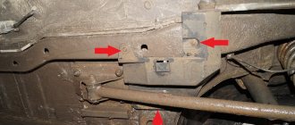
The main location of the block is to the left of the steering column. The device is closed from below with a special lid. You only need to unscrew two screws to get to the internal contents. After this, squeeze out the upper edge of the lid, gradually freeing this part from all fasteners. The entire connection diagram for the VAZ 2123 speed sensor and other devices becomes available.
A block will appear, which is held on a special bracket. Depending on the configuration and year of manufacture, the circuit itself varies, as does the total number of fuses.
Pinout of Niva Chevrolet connectors responsible for the front part of the wiring
- 1/6 – front right/left headlight block;
- 2 – joint assembly of the machine starter;
- 3 – voltage supply for traction starter;
- 4 – battery connection terminals;
- 5 – generator module for powering the electrical circuit;
- 7/15 – units for combining head optics fog lights;
- 8 – contact group for the drive of the electric motor for the front windshield washer;
- 9 – input of a temperature sensor that measures indicators outside the vehicle;
- 10 – contact plug for the engine compartment lighting lamp;
- 12 – standard sensor for measuring the remaining brake fluid level;
- 13 – plug of the standard electric motor for driving the windshield wiper;
- 14 – designation of a standard horn;
- 16/17 – plug inputs to the dashboard.
Minor repairs: restoring the driver's door switch
Greetings to readers and guests of the logbook of my car. Today I dealt with a breakdown that affected many shnivovods - a non-working limit switch in the door lock. Most often, the driver's door mic breaks, and that's understandable - the most popular door in the car))) Specifically, my mic has malfunctioned before, but rarely - about once a month, you open the door - the light does not come on, and the homemade door open indicator blinks for a fraction seconds. Usually it helped to slam the door hard a couple of times and everything would be restored, but since the day before yesterday this method stopped working. Therefore, today I dismantled the lock to study and defect the little bastard))
So, the first thing to do is to remove the door trim (for those who don’t know how, look here) and bend back the polyethylene in the lock area:
My driver's door microphone was acting up, but I think the locks on the other doors can be removed in the same way) Next, unscrew the 3 screws securing the lock to the door:
Next, we unhook the interfering rods: first, the rod on the inside door handle:
Simply lift the plastic latch up and remove the rod:
Next, use a thin screwdriver to unhook the rod on the door soldier and take it out. We also pay attention to the lock actuator rod (red arrow) - it doesn’t interfere with disassembling, but during reassembly it will need to be put back as it was)
Unwind the gray tape and disconnect the 3 plugs:
Remove the rod on the lock cylinder with a wide flat screwdriver:
... and in a similar way, pull from the outer door handle:
After this, the lock can be removed from the door:
To disassemble the lock, unscrew 3 self-tapping screws (the red arrow is a pin that comes out a little tight when disassembling)
...and unfasten these latches:
Then we move the lock cover to the side from under the mustache:
Now you can take out the mikrik - here it is, the brat)
By the way, the microphone is normally closed, when the doors are closed - the microphone bracket is pressed and the contacts open) We disassemble it with a thin screwdriver, but CAREFULLY
- Small parts inside!
Using tweezers, carefully remove the “spring” and remove the “contact”
And here is the very reason for the mikrik not working - a speck of soot:
Cleaned it out with a thin file.
After which you can reassemble everything in reverse order. In this case, you need to pay attention to: 1) We insert the micrik spring with tweezers and very carefully - it tries to fly away 2) When assembling the lock cover, you need to ensure that the tabs in it fall into place: the left one should fall into the hole, and the right one should go to the left of the plate:
3) The pull rods on the lock cylinder and on the outer handle are put on quite tightly.
Source
Chevrolet Niva wiring diagram, part of the ECM
- 1 – spark plug pins;
- 2 – contact group of injector drivers;
- 3 – ignition unit;
- 4 – control controller;
- 5 – main protective relay of the internal combustion engine;
- 6 – area for location of fuse links;
- 7 – main relay fuse;
- 8/9 – protective circuits of the right and left head fans of the radiator;
- 10 – protective element for the control fuse of the main fuel pump;
- 11 – controller circuit fuse;
- 12 – secondary protective element of the main radiator fan on the right side;
- 13 – auxiliary fuse of the above circuit;
- 14 – fusible link of the fuel pump control circuit;
- 15 – fan of the main radiator, located on the left side;
- 16 – standard oxygen concentration sensor in the intake manifold;
- 17 – drain output of the detonation channel meter;
- 18 – DPKV output;
- 19 – control by the adsorber purge valve;
- 20 – output of the mass air flow sensor group;
- 21 – idle speed control drive;
- 22/23 – activation of the left/right fan motor of the main engine cooling system;
- 24 – auxiliary resistor;
- 25 – control of the TPS device;
- 26 – output from antifreeze temperature sensor;
- 27 – status indicator of the above-described sensor;
- 28 – standard module for measuring lubricant pressure in the crankcase compartment of the power plant;
- A/B – battery terminal blocks;
- C – “mother” input for connecting to the dashboard;
- G1/G2 – grounding outputs of the wiring section.
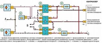
Electrical Harness System
Due to the ignition system, a spark appears in the cylinders corresponding to the current power strokes. In modern engines, wires go to sensors that are responsible for monitoring several indicators:
- Motor temperature.
- Ignition, and so on. The injector also becomes an important part.
The ignition system harness is in most cases connected to several other parts:
- controller;
- instrument panels;
- "mass".
Next, the wires are sent to the rear harness. Moving on to the engine compartment, the main harness splits into two wires. Of these, the largest is sent to the radiator, connecting with the following components along the way:
- DMRV.
- Crankshaft sensor.
- Resistor.
- Electric fans.
Through the power steering pump, other wires are thrown from the core, going to additional sensors:
- phases;
- idle move;
- throttle valve;
- detonation;
- injectors - a fuse for them is not added to the system.
Due to the wiring, the operation of the engine is clearly controlled. Ensures uninterrupted operation regardless of environmental conditions.
The second core goes up, after which it is divided into two parts. The wires to the plus and minus go to the right. The battery is also located there. To the left they connect to the adsorber, fuel pressure sensor and oxygen sensor. This is how electrical wiring is arranged in most cases.
Also interesting: VAZ Niva 2121 tuning recommendations
A branch from the harness may go to the air conditioning fuse if the car is equipped with such equipment.
If even one part of this system shorts, there is a high probability that the engine simply will not start. The controller stops seeing information regarding temperature, fuel supply to the injectors, and throttle valve position.
Under such circumstances, it is better not to resort to diagnostics, but to replace the entire harness at once. It may take too much time to find one wire, and the result will be questionable. The wiring works better when new.
Niva electrical circuit responsible for the equipment built into the front doors
The following is a general breakdown of the electrical equipment of Chevrolet Niva car doors manufactured after 2009. The representation is based on the fact that both sides are almost identical:
- 1/10 – door position limit switches;
- 2/11 – drive of electric window regulator gearboxes;
- 3/12 – plugs for control drives for adjusting the position of rear-view mirrors;
- 4/13 – door lock gearboxes;
- 5/14 – standard terminal blocks for the speaker outputs of the standard acoustic module;
- 6/15 – window switch drives.
Niva electrical circuit responsible for the equipment built into the cargo compartment door
- 1 – output of the contact group of the rear bundle of highways;
- 2 – door position limit switch;
- 3 – central locking gearbox;
- 4 – voltage for the rear windshield washer motor;
- 5 – plug for additional brake sign;
- 6 – heated aft windshield;
- 7 – stern glass wiper controller;
- 8 – relay of the above element.
Car alarm connection points for Niva Chevrolet 2010
Driver's door – white/blue Passenger's door – yellow/black Rear doors – white/black trunk – white/red hood – green/black All limit switches are negative
Turns – blue and blue/black
Central locking block behind the mounting block. Central lock (-) – closing – 7th leg, opening – 2nd leg. To control the central locking, you need to solder to the block.
On this car, the first press of the standard key fob opens the driver's door, the second press opens the passenger door. One of the well-known sites has connection points using an additional relay. But I don’t think this method is the best. That's why I offer mine. The central locking unit on the Chevy Niva is from Kalina.
Instrument panel pinout
Here is a description of the terminals and terminals of standard instrument panel wiring:
- 1 – diagnostic output, located on the underside of the board under the steering wheel;
- 2 – plug connector for connecting the ECM;
- 3/4 – standard modules for connecting the front connection of the cores responsible for the engine control systems;
- 5/7 – left and right steering column switches;
- 6 – ignition switch device connector;
- 8 – instrument panel combination;
- 9 – output for powering the connector of the contact group of the interior ventilation and heating system;
- 10/11 – lighting plugs for the above equipment;
- 12 – button switch of the alarm device;
- 13 – mounting box for fuse insertion;
- 14/15 – the lamp itself and the button to turn off the lighting of the glove compartment;
- 16 – contact pin for turning off the brake lights;
- 17 – switch of the standard sound warning module (horn);
- 18 – automatic protection of fog lights of head optics;
- 19 – automatic window lifters;
- 20 – protective relay for sound signal;
- 21 – safety module for the seat heating system;
- 22 – starter control relay;
- 23 – switch for the external lighting system;
- 24 – contact group for connecting the stove fan;
- 25 – built-in switch for turning on the heated windshield;
- 26 – device for turning off the front fog lights;
- 27 – switch for stern lights, fog lighting group;
- 28 – air conditioner setting button;
- 29 – position regulator of heating manipulators;
- 30 – cigarette lighter pin;
- 31 – buttons for adjusting the direction of the light flux of the head optics;
- 32 – adjust the brightness of the instrument panel illumination;
- 33 – auxiliary resistor mechanism of the heating fan;
- 34 – standard immobilizer module;
- 35/36 – standard-type onboard acoustic module terminals;
- 37/38 – terminal connectors for connecting the rear harness of the on-board circuit.
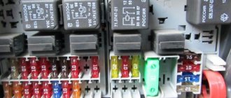
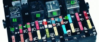
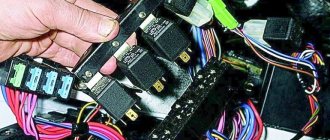
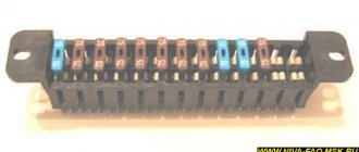
Relay and fuse locations
The main part of the fuses is located inside the cabin, under the panel to the left of the steering column. There are four blocks in total:
- Engine control system fuses.
- Windshield wiper.
- General fuses.
- The engine management system, which is always complemented by the Chevy Niva circuit.
The last block is located at the bottom.
The main and additional blocks are always connected to each other. 10 fuses are included in the top block. There are six of them in the lower one. Cooling works, among other things, due to such a device.
The relay box for the engine management system is located below the main, additional fuse box. There are a total of five relays and one fuse in this part. Sometimes the so-called starter relay is additionally included in the circuit; the year of manufacture becomes the determining factor.
There are also mounting blocks, which are also located to the right or left of the steering column.
Wiring diagram of the VAZ Niva, the part responsible for powering the head optics
- 1 – main lighting device;
- 2 – fuse box;
- 3 – headlight switching regulator;
- 4 – part of turning off the ignition;
- 5 – headlight switches;
- 6 – designation in the instrument cluster of the area responsible for turning on the high beam;
- K4/5 – protective relays for turning on the high- and low-range modes of the head optics;
- A – terminal pins going to the circuit’s power source.
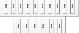
Pinout of contacts of the Niva Chevrolet fuse mounting block
The car is supplied to the market with several types of mounting blocks. The exact type of device depends on the configuration of the vehicle and its year of manufacture. Further description is given using the example of Bosch M,1,5,4:
- 1 – cylinder ignition system;
- 2 – empty;
- 3 – fuel pump connection contact;
- 4 – stepper motor;
- 5 – free;
- 6 – connection of the main power plant cooling fuse;
- 7 – incoming pulse from the MRI;
- 8 – empty;
- 9 – standard speedometer;
- 10 – not busy;
- 11 – knock sensor;
- 12 – voltage supply for sensors;
- 13 – L-line;
- 14 – weight on the body from the injectors;
- 15 – control of injector drives for cylinders 1-4;
- 16/17 – not used;
- 18 – power supply of devices from 12 volts;
- 19 – common ground cable for electrical appliances;
- 20 – ignition supply to cylinders 2 and 3;
- 21 – stepper motor terminal;
- 22 – engine check lamp;
- 23 – empty;
- 24 – mass of the stepper motor;
- 25 – air conditioning system relay output;
- 26/29 – stepper power plant;
- 27 – voltage to terminal No. 15 of the ignition switch;
- 28 – empty;
- 30 – mass of motor control sensors;
- 31/32 – not applicable;
- 33 – control of settings of injector drivers for cylinders No. 2/3;
- 34-36 – empty;
- 37 – device for powering the main relay;
- 38-40 – not used;
- 41 – submitting a request for an air conditioning module inside the cabin;
- 42 – empty;
- 43 – tachometer control signal;
- 44 – signal supply from the potentiometer;
- 45 – DTOZH;
- 46 – control of the main relay;
- 47 – device for confirming admission to ECU programming;
- 48 – low level of impulse from DPKV;
- 49 – opposite meaning;
- 50-52 – empty;
- 53 – receiving an impulse from the TPS;
- 54 – fuel consumption detail;
- 55 – K-line.
Car alarm connection points for Chevrolet Niva 2022, immo number 1118-6512010
Bypass immo on the steering column: white wire into the gap to the lineman.
All limit switches are on the immobilizer block.
The central locking unit does not have to be disassembled and soldered in there. Everything works perfectly according to the Priora scheme: a thin blue wire to the gap (the gap is closed, it is to ground - open).
Turns – blue and blue/black. Can be found in the gray connector, under the mounting block.
Monitoring engine operation (+) – one wire comes out of the generator very conveniently. We take it from him.
The handbrake is torn off and connected via a diode, otherwise it won’t work.
Keep in mind that removing the dashboard requires 4 self-tapping screws, but in the center of the panel it is so tightly latched that it is only possible to break this fastening bracket. Or install the whitefish behind the mounting block.
Articles on the topic
Alarm installation cards for Chevrolet Niva
“>
Prevention
To prevent breakdowns, the manufacturer recommends following several tips.
- Once a year, treat all terminals and connectors with special oil - this will prevent the formation of oxides.
- Periodically check the tightness of the contact connectors. If the connections are loosened, short circuits may form or the conductivity of the circuit may decrease, which will be perceived by the ECU as a mechanism failure.
- Check the degree of wear of power cables and lines. During active use of the vehicle, braids made of flexible polymer may wear out and crack. This circumstance can provoke short circuits and mechanical shedding of insulators. Therefore, it is better to prevent a breakdown than to fix it.
If you adhere to the above rules, the car will serve for a long time and with high quality all the time.
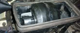
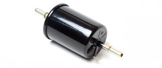
Connection between battery and starter
Each car has its own starter installation scheme. There may be several access options:
- on right;
- left;
- from the radiator side;
- from the salon side.
It is often necessary to use a lift or inspection hole to reach this component. The mechanism is needed to ensure engagement between the gear and the flywheel. Therefore, the device is most often located in the area where the clutch housing is attached. The electronic version is no exception.
For connection, only one connector is used, to which a special terminal is added. The starter starts working every time the owner turns the key.
It is best to use a multimeter to detect breakdowns in one of these parts of the car. But faults can be easily determined using other simple manipulations.
In most cases, repairing the starter is possible, even if such an important part as the windings has failed. The electrical equipment of a car in most areas is subject to complete restoration.