Schematic electrical diagrams, connecting devices and pinouts of connectors
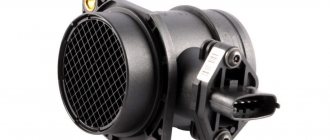
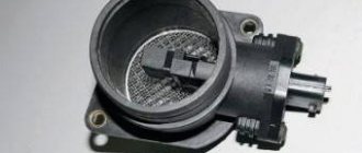
Based on the signal from the mass air flow sensor (MAF), the cyclic filling of the cylinder is calculated, which is ultimately converted into the duration of the injector opening pulse. If it does not work correctly, the car consumes more gasoline than necessary. Such a sensor is installed on the second path, immediately behind the air filter and connected to the electrical system, which is controlled by a six-pin block of wires.
There are quite a few different types of mass air flow sensors: mechanical, ultrasonic, hot-wire and some others.
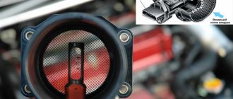
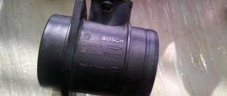
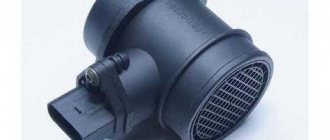
In this case, we will consider the design of the HFM-5 hot-wire sensor from Bosch, which is most often installed on VAZ cars. The sensor's sensitive element is a thin film on which several temperature sensors and a heating resistor are located. In the middle of the film there is a heating area, the degree of heating of which is controlled using a temperature sensor.
On the surface of the film, on the side of the air flow and on the opposite side, two more thermal sensors are located symmetrically, which record the same temperature in the absence of air flow. In the presence of air flow, the first sensor is cooled, and the temperature of the second remains unchanged, due to the heating of the air flow in the heater zone. The differential signal of both sensors is proportional to the mass of passing air.
- 1 - dielectric diaphragm
- H - heating resistor
- SH - Temperature sensor naked. resistor
- SL - Air temperature sensor
- S1 and S2 - temp sensors before and after the heater.
- QLM - air flow mass
- t—temperature
The sensor's electronic circuit converts this signal into a constant voltage proportional to the air mass. This design is called Hot Film (HFM), its advantages include high measurement accuracy and the ability to record reverse air flow, but its disadvantages include low reliability in conditions of contamination and moisture.
To measure the amount of air that enters the engine means to determine the engine load. When the driver presses the gas pedal, the throttle valve opens and the amount of intake air increases. At the same time, we say that the load has increased. When you release the pedal, the load drops. It's quite simple. However, this is only at first glance. If we take into account the fact that in real driving conditions the engine often changes operating modes and the incoming air in the intake system participates in several gas-dynamic processes, then the problem of measuring the air in the system is not so simple.
In older systems (ECU January-4 and GM-ISFI-2S), other hot-wire mass flow sensors were used, the sensitive elements of which were made in the form of threads. Such sensors are called Hot Wire MAF Sensor. The output signal of these sensors was frequency, that is, depending on the air flow, it was not the voltage that changed, but the frequency of the output pulses. The sensors were less accurate and did not allow registering reverse flow, but these shortcomings were offset by very high reliability.
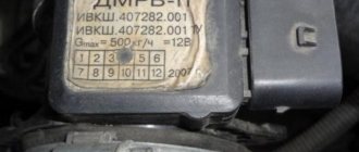
Several types of mass air flow sensors were installed on VAZ cars: GM, BOSCH, SIEMENS and Russian-made. In 1999-2004 Two types of sensors were installed on VAZ cars: 0 280 218-037 and 0 280 218-004. These sensors produce different output voltage (calibration) parameters at the same air flow rate and interchangeability (or rather, replacing 004 with 037) is only possible with the replacement of calibration tables in the firmware. The same applies to the new sensor 116, which has been installed as standard since the beginning of 2005.
The sensor is supplied only assembled, with a code and marked with a green circle.
On some classic cars, together with the January 7.2 ECU, Siemens-VDO sensors (5WK97014. AVTEL) were used:
They differ in calibration (from zero volts) and connection diagram.
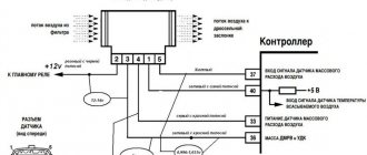
VAZ 2110 air sensor pinout diagram
- Yellow (closest to the windshield) - mass air flow sensor signal input;
- Gray-white—sensor supply voltage output;
- Green — sensor grounding output;
- Pink-black - to the main relay.
The wire colors may change, but the pin locations remain the same.
Let’s also add that the mass air flow sensor with endings 004, 037, 116 (for Bosch) and 00, 10, 20 (for Pekar) are different in calibration. You can only change it by flashing it.
Ignition coils
On the original Bosch ignition coils, the quality of the drawings is more accurate and clearer. On the fake, all the drawings are shown with dotted lines - ordinary strokes.
The inscriptions on the packages are identical, the stickers are also identical.
Let's see what's inside. Even at first glance, a fake reel looks just like Chinese trash - it does not match the quality of BOSCH. The stickers are green everywhere. On the original it is darker, on the fake it is lighter.
If you look closely, the contacts to which the high-voltage wires are connected are all crooked, that is, one looks to the left, the other to the right.
The metal color of the contacts inside is yellow, on the original it is white. Made carefully.
Friends, don’t give counterfeit manufacturers a chance, don’t buy fakes. Be careful, don't be fooled.
Connecting the MAF air sensor VAZ 2112
If the mass air flow sensor is operational, then when the engine is running at 900 rpm, the volume of air used will be at least 10 kg per hour. When the speed increases to 2 thousand, this figure will increase to approximately 20 kg. If the volume of air at such speeds drops, the dynamics of the vehicle will also decrease, and accordingly, this will lead to a decrease in gasoline consumption.
If these indicators increase, this will also contribute to an increase in fuel volume. Deviations of the parameter by 2-3 kg should not be allowed, since in this case the operation of the power unit may be incorrect.
How to check the mass air flow sensor of a VAZ with a millimeter
To check the sensor readings, you need to take a multimeter, set it to measure direct current, and the higher the accuracy you choose, the better (if it is possible to measure units (2 V), it is better to choose it, but 20V will do). And place the negative probe on the engine ground or the negative terminal of the battery, and the positive probe on the fifth signal wire of the mass air flow sensor connector.
The easiest way to check is to remove the connector from the mass air flow sensor. And observe changes in engine performance. However, this option is not always true. The fact is that when the connector is disconnected, the ECU goes into emergency mode and regulates the mixture using the throttle position sensor, and at the same time the mixture becomes richer and, perhaps, even with a working mass air flow sensor, engine operation will be smoother.
There is an option to take the mass air flow sensor from a working car and install it on your own. Everything is simple here, and there is nothing to describe.
Checks without diagnostic equipment and a multimeter may be unreliable, since if the sensor is working correctly, but if there is an extraneous air leak, there may also be problems with adjusting the mixture.
Connection diagram for air flow sensor 2114
A common cause of incorrect operation of the mass air flow sensor is the failure of electronic components, which increases the sensor’s response time to changes in air flow. A working sensor monitors changes at a speed of 0.5 ms, and if it breaks down, the response time increases by 20-30 times. The defect is detected only by recording the operation graph with an oscilloscope. Such a sensor cannot be repaired; it must be replaced with a new one.
Making an “eternal” mass air flow sensor on ATiny13
This project appeared due to the reluctance to buy a part that had been in use for about 30 (thirty) years for a quite considerable amount of 3,000 - 5,000 rubles. We can say that this will be a test of the pen in circuit design and programming of microcontrollers. If you're interested, see the continuation below the cut.
Be careful there are a lot of photos!
So, we start propping up the bikes with crutches.
Input data
BMW E30 coupe 1986 with M10B18 engine (4 cylinders, 1.8L, injection):
Checking the air sensor yourself
When a malfunction of the mass air flow sensor occurs, the air-fuel mixture becomes over-rich or lean, which immediately affects the operation of the engine and may ultimately result in engine failure.
Symptoms of a malfunctioning mass air flow sensor:
- Check Engine error appears;
- Increased fuel consumption;
- Doesn't start well when hot;
- The car began to accelerate slowly;
- Engine power lost.
The easiest way to check the mass air flow sensor on a VAZ 2114 is to disconnect the plug. If there is no signal, the engine control unit goes into emergency operation mode, determining the approximate air volume based on the throttle position. At the same time, fuel consumption increases slightly - for the VAZ 2114 it reaches 10-12 liters per 100 km. A characteristic feature is the increase in idle speed to 1500 rpm. But when using a January 7.2 or Bosch M7.9.7 controller, the idle speed does not increase due to the software features.
The normal voltage at the output of the new sensor is 0.996 - 1.01 Volts. During operation, it gradually changes and, as a rule, increases. The greater the value of this voltage, the greater the wear of the mass air flow sensor.
Here is the reference voltage in volts:
- 1.01 - 1.02 - good condition of the sensor.
- 1.02 - 1.03 - not a bad condition.
- 1.03 - 1.04 - the resource of the mass flow sensor is coming to an end.
- 1.04 - 1.05 - emergency condition.
- 1.05 and above - it’s time to replace the mass air flow sensor.
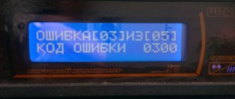
The measurement is made between the yellow and green wires. Voltage values can be displayed on the screen of some on-board computers (menu voltage from sensors, U Mass air flow sensor).
Important: the limits and fluctuations of the output voltage in at least 30% of cases for a faulty sensor will be NORMAL and will not cause the “Check” icon on the panel. That is, voltage measurements are not very informative, but the rate that it will produce in kilograms of air will correspond to the movement not where it actually is, and the ECU will interfere with the mixture based on it - hence the extra consumption!
You need to check the sensor at a service center, preferably with a proprietary scanner, which itself indicates by blinking if there is a imbalance in some parameter (in this case, air flow in kilograms), comparing it with the reference values stored in its memory.
What is the difference between sensors 037 and 116?
How can the regulators of these models differ from each other and is it possible to install 116 instead of 037? There are differences between these controllers, and the point is not in the MAF pinout. After all, if these models were the same, what would be the point of giving them different names?
So, how do the controllers differ from each other and is it possible to install model 116 instead of 037:
- The first difference that can be guessed based on the technical characteristics is that the 037 model can produce data with an error during operation. Of course, an error of 2.5% is not critical, but it does exist.
- Device 037 is intended for installation in VAZ 2111, 2112, 2123, 21214 cars, which are equipped with controllers M 1.5.4, January 5.1-5.1.3, etc.
- As for model 116, its use is relevant on Ladas 21114, 21124, 21214. Installation of this device is allowed on Kalina and Priora. Installation of the device is allowed on cars equipped with M 7.9.7 and January 7.2 controllers.
If you encounter a problem with the device not working, then when replacing it you need to install the same model that has already been installed. But it is worth considering that 037 is not a common option like 116, so it is more difficult to find. The latter, in turn, is more common, and its cost is lower.
Replacement is allowed, but experts do not recommend this. This is because these devices differ in their calibration, so in case of replacement, you will have to change the parameters of the control unit. And you can only get into the “brains” of a car if you understand what needs to be done and have minimal experience.
Loading …
Replacing the sensor - instructions
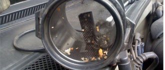
Using a screwdriver, unscrew the clamp of the air intake corrugation at the sensor outlet, pull it off and carefully inspect the internal surfaces of the sensor itself and the corrugation. These surfaces must be dry and clean; traces of condensation and oil are unacceptable. If the air filter is changed rarely, then dirt getting on the sensitive element of the sensor is the most common cause of its breakdown in VAZ cars.
There may be oil in the mass air flow sensor as a result of an increased oil level in the engine crankcase, or the oil sump of the crankcase ventilation system is clogged.
Next, unscrew the 2 screws of the sensor with a 10mm wrench and remove it from the air filter housing. There should be a rubber sealing ring on its front part (at the entrance edge). It prevents unfiltered air from being sucked into the intake tract through the sensor.
Determining when to replace
A new flow meter is installed only after the old one breaks down. Sometimes it is “reanimated” by thorough purging, but even in this case the device will not work long enough.
The main reasons for replacement are dirt and time. If in the case of time everything is relatively clear (heating elements cannot last forever), then contamination occurs for several reasons. The most common is the inability of the air filter to cope with its tasks. If such a filter fails, the driver has a couple of thousand kilometers left - after that the quality of the engine will drop significantly. Also, the poor condition of the wiring hurts the flow meter.
Monitor the condition of the engine. Oil vapors entering the air duct accelerate wear of the air flow sensor. The causes of oil vapors are wear of valve seals and piston rings.
DMRV of VAZ 2115 car
VAZ 2115 cars are the last link in the Samara family and inherited the range of engines from it. Accordingly, the engine ECU controllers and the mass air flow sensors combined with them are similar. Flow meter compatibility is determined by the ECU type, and is as follows:
- ICE VAZ 2111 - Mass air flow sensor 0 280 218 004 (obsolete) or 0 280 218 037, environmental standard Euro 2;
- ICE VAZ 21114 - MAF 0 280 218 116, environmental standard Euro 2;
- ICE VAZ 211183 - Mass air flow sensor 0 280 218 116, environmental standard Euro 3.
Actually, ecology is not related to the type of flow meter; exhaust toxicity is set by the settings of the ECU controller.
How does it work
The mass air flow sensor reports to the ECU data on the mass of air flow, which changes following changes in the opening angle of the throttle valve (therefore, the device is placed in close proximity to the throttle).
Having processed the information, the ECU controller commands the injectors to inject a certain amount of fuel. As a result, the engine always runs efficiently and economically.
The design of the mass air flow sensor of VAZ 2115 cars is simple and reliable: a precision resistor sets the reference resistance, paired with it in a bridge circuit is a variable resistor made of platinum wire. Its indicators change with temperature changes. Both sensors are located in the air flow. The variable resistor is heated by a precisely selected voltage. To compensate for cooling, the voltage value is constantly changing to ensure the desired temperature.
The voltage readings (signal from the VAZ mass air flow sensor) are analyzed by the ECU, and, according to a calibrated schedule, the volume (more precisely, weight) of air in kg per unit of time is determined.
What is a mass air flow sensor, why is it important and how to diagnose its malfunction
Over the past three decades, engines with distributed and direct fuel injection have finally supplanted all other types of designs. It would seem that this is a considerable period of time, but engineers have not been able to overcome the “childhood diseases” of important electronic components, including the mass air flow sensor (MAF), which is responsible for the composition of the air-fuel mixture. Let's remember how the mass air flow sensor works, why it is so important and how to diagnose its malfunction.
What is DMRV
Modern engines use two types of power supply systems: with distributed injection, the nozzle supplies fuel to the intake pipe, with direct injection, it supplies fuel to the combustion chamber. For both systems, the correct operation of the mass air flow sensor, which was once mechanical (vane type), but is now devoid of moving mechanical parts and made hot-wire (from “anemo” - wind), is important.
Factory air flow sensor made in Germany for a VAZ engine
The mass air flow sensor can be installed not only on a gasoline engine, but also on a diesel engine, where the operation of the EGR valve (exhaust gas recirculation system) is “tied” to it.
As old-school drivers used to say, an internal combustion engine does not work in two cases: there is nothing to burn or there is nothing to set it on fire. The mass air flow sensor precisely informs the electronic control unit about the amount of incoming air, the oxygen of which becomes the “fuel” for the working mixture. Having received such a signal, the ECU can ensure the most complete combustion possible. The device, located in the intake tract, consists of two resistors, which can be designed in various designs. In the first case, the resistor is exposed to passing air: when the flow intensity changes, it cools and its internal resistance changes. In the second case, it is not blown - based on the difference in readings from two resistors, the volume of air that needs to be supplied to the cylinders is calculated.
The sensor is supplied to the aftermarket with protective caps to prevent contamination during transportation.
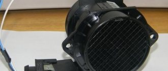
This is what the sensor looks like on a regular VAZ engine. It will not be possible to remove it from the case without a special key.
The removed sensor is in its “bare” state. The sensitive element is clearly visible
Based on the data on the mass and temperature of the incoming air, the ECU determines its density, and also calculates the duration of opening of the injectors and the amount of fuel supplied to the combustion chamber. In general, the mass air flow sensor is important for achieving maximum engine power, for more complete combustion (environmentally friendly), and for economical driving. The failure of this sensor, like most others, causes the Check Engine warning light to go off.
The check engine light can come on for any reason. If there is no on-board computer with a diagnostic function, you will have to go to a service station where there is a scanner
However, the owner does not always associate the triggered “check” with the mass air flow sensor - especially if the engine runs without any interruptions, and the dynamic characteristics of the car have not deteriorated at all. Therefore, it is important not to leave the illuminated engine malfunction indicator unattended, but to consider errors with the diagnostic computer.
What happens if the mass air flow sensor is faulty
The ECU controller will stop receiving or receive distorted air mass data, resulting in the fuel-air mixture being formed incorrectly. The result is a loss of power and torque (in VAZ cars these parameters are not too high anyway), as well as an increase in fuel consumption.
Signs of a malfunction of the mass air flow sensor - absence or incorrect value of the information signal from contact No. 5 of the sensor connector. If the sensors break down, an overestimation of indicators is first observed (up to 25%), then a complete cessation of information output. This leads to the following symptoms:
- on a cold internal combustion engine, the speed is increased by at least a third;
- with a sharp release of gas, the speed first remains at the same level, then slowly decreases;
- fuel consumption increases significantly;
- the car may stall immediately after starting;
- lacks acceleration dynamics and traction under load.
Causes of malfunctions
In 90% of cases, this is contamination of sensitive sensors.
- a low-quality (not certified) or incorrectly installed air filter allows dust to enter the mass air flow sensor measuring channel;
- when operating the vehicle in wet weather or driving through puddles, droplets of water may enter the intake manifold;
- If the crankcase ventilation system does not work (damaged hoses, broken valve), drops of oil enter the air duct pipe.
How to check the flow meter on a VAZ 2115 yourself
- If the “Check Engine” light comes on on the dashboard, you can determine errors using OBD codes using a car scanner. However, such equipment is not always at hand.
- The initial check can be carried out by simply disconnecting the flow meter connector and comparing the behavior of the engine with and without the mass air flow sensor. After disconnecting a working sensor, the car's behavior should worsen. A broken flow meter when disconnected will not change the operation of the motor.
- And finally, a relatively accurate test using a multimeter. It is carried out in two stages. First, the power supply to the device is checked with the disconnected connector. From the ECU, 12 volts should be supplied to pin 2, and 5 volts to pin 4. Measurements are made relative to weight, with the ignition on and the engine turned off. Then the voltage of the sensor signal is measured at the connected connector in a resting state (ignition on, engine not running). To do this, you need to equip yourself with a relatively accurate multimeter that can measure voltage with an error of up to 1/100 volt.
Regarding ground, there should be a voltage of 0.99 to 1.02 volts at pin No. 5. It is possible to increase the value to 1.05 volts, but this indicates a high degree of wear on the mass air flow sensors.
The principle of operation of the HFM5 mass air flow sensor from BOSCH on a VAZ
The main measuring element in the sensor is a film or wire element heated to a certain temperature. Due to the air flow, this element is cooled, and the microcircuit (usually built into the sensor itself) tries to maintain the same set temperature. And so, depending on how much power is required to heat a given element, the air passing through is calculated. Flow information is transmitted to the ECU in the form of an analog voltage, and in some sensors in the form of a pulse frequency.
Measurements of air flow in the mass air flow sensor are carried out within 0...5 V. At the moment when the car is turned off and the ignition is turned on, the ADC signal from the sensor should be within 1 V. Readings within 0.996 - 1.0 V are considered ideal. 1.02 - 1.025 are still allowed, and a voltage greater than 1.035 already indicates that the measuring element is dirty or has failed for other reasons.