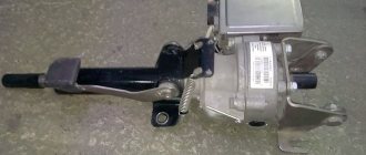
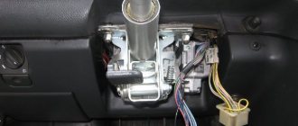
Electric power steering (EUR or EMURU) 11186-3450008: 1 - steering shaft, 2 - electric motor, 3 - electronic control unit, 4 - torque sensor, 5 - rotor position sensor
In electromechanical power steering, the necessary compensation force is created by an electric motor. In general, the EUR consists of the following main components:
– steering shaft with torsion bar drive;
– electronic control unit (ECU);
– torque sensor;
– rotor position sensor.
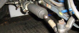
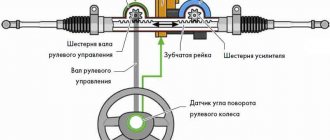
The EUR is installed on the steering shaft, the parts of which are connected to each other by a torsion shaft with a torque sensor installed on it. When the steering wheel rotates, the torsion shaft twists, which is recorded by the torque sensor. Next, information from this sensor goes to the ECU, which calculates the required compensation force (taking into account the readings of the vehicle speed sensor) supplied to the steering shaft by the electric motor included in the ESD. In general, the EUR can be located both on the steering column and on the steering rack. In the latter case, the load on the steering shaft and its joints is reduced.
The advantages of the ESD relative to the power steering are the simplicity of the design and the compactness of the mechanism. In this case, the power steering is activated only when the steering wheel is rotated, while the power steering pump works constantly, creating additional load on the engine and, accordingly, increasing fuel consumption. The ESD is also flexible in configuration, allowing you to change the steering feel by changing the control program. The advantages of power steering include “honest” feedback and resistance to high loads, which allows it to be used on SUVs, trucks and other heavy equipment, while electric steering is usually installed on passenger cars.
In the LADA KALINA car, the electric power amplifier is located on the steering column. The brushless electric motor included in the EUR is connected to the steering shaft through a gearbox. The EUR electric motor is powered from the vehicle's on-board network. The ESD remains operational when the on-board network voltage changes in the range of 10.8 – 15 V. The nominal supply voltage of the ESD is 13.5 V; for a load torque of 35 Nm, the maximum current consumption does not exceed 50 A.
Rice. 2. Electrical connection diagram for electric power steering 11186-3450008
Table 1. Purpose of electrical amplifier connector pins
| Block | Contact | Address |
| X1 | 1 | + 12 V from battery |
| 2 | "Minus" from the battery | |
| X2 | 1 | + 12 V from terminal “15” of the ignition switch |
| 2 | Tachometer signal input | |
| 3 | Speed sensor signal input | |
| 4 | Output to EUR status indicator | |
| 5 | “K-line” output to the diagnostic block | |
| 6 | Output “L-line” (not used) | |
| 7 | Common wire (“ground”) | |
| 8 | Technological output (not involved) | |
| HZ | A1 | Motor phase A |
| A2 | Motor phase A | |
| IN 1 | Motor phase B | |
| AT 2 | Motor phase B | |
| C1 | Phase C of the electric motor | |
| C2 | Phase C of the electric motor | |
| X4 | 1 | Common wire 1 torque sensor |
| 2 | Common wire 2 torque sensors | |
| 3 | Torque sensor power supply | |
| 4 | Torque sensor output 1 | |
| 5 | Torque sensor output 2 | |
| 6 | 250 kHz frequency signal input | |
| X5 | 1 | Common wire of the rotor position sensor |
| 2 | Rotor position sensor phase A output | |
| 3 | Phase B output of the rotor position sensor | |
| 4 | Phase C output of the rotor position sensor | |
| 5 | Supply voltage +5 V rotor position sensor |
The maximum compensating torque on the steering shaft can reach 30 Nm; the EUR provides such a torque when the vehicle is stationary; with increasing speed, the compensating torque decreases proportionally. The initial data for the electric motor control system is information about the torque on the steering shaft, the position of the rotor and the vehicle speed, obtained from the corresponding sensors.
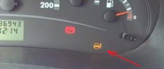
For EUR 11186-3450008 there are 4 operating modes: “Self-testing”, “Readiness”, “Compensation”, “Failure”. To indicate the status of the EUR, there is a status indicator on the vehicle dashboard (Fig. 3).
Rice. 3. Location of the power steering status indicator
When you turn on the car’s ignition, the EUR goes into the “Self-test” mode, which checks the serviceability of the system. If malfunctions are detected during the self-testing process (negative self-test result), the ESD switches to the “Failure” mode, and a malfunction code is entered into the memory of the ESD control unit (see Table 2).
Table 2. Electric power steering ECU error codes
| Code | Code Description |
| S1000 | No errors found |
| S1011 | Car engine speed signal circuit, no signal |
| S1012 | Vehicle speed sensor signal circuit, no signal |
| S1013 | The vehicle's on-board voltage is below the minimum threshold |
| S1014 | Voltage at the ignition switch is below the minimum threshold |
| S1021 | Torque sensor main terminal voltage |
| S1022 | Torque sensor control pin voltage |
| S1023 | Incorrect signal from the main and/or control output of the torque sensor |
| S1024 | Torque sensor, no signal |
| S1031 | Steering shaft position sensor, main signal circuit malfunction or out of range |
| S1032 | Steering shaft position sensor, control signal circuit malfunction or out of range |
| S1033 | Steering shaft position sensor, no power |
| S1041 | Engine rotor position sensor, phase A circuit malfunction or out of range |
| S1042 | Engine rotor position sensor, phase B circuit malfunction or out of range |
| S1043 | Engine rotor position sensor, phase C circuit malfunction or out of range |
| S1044 | Rotor Position Sensor Sequence Incorrect |
| S1045 | Motor rotor position sensor, no power |
| S1050 | Short circuit to ground in power circuits |
| S1051 | Motor, excess current through phase winding A |
| S1052 | Motor, current overcurrent through phase winding B |
| S1053 | Motor, excess current through phase winding C |
| S1054 | Motor, broken phase windings |
| S1055 | Motor, open phase winding A |
| S1056 | Motor, open phase winding B |
| S1057 | Motor, open phase winding C |
| S1058 | Motor, phase winding short circuit |
| S1059 | Motor phase A winding short circuit |
| S1060 | Motor phase B winding short circuit |
| S1061 | Motor phase winding short circuit |
| S1070 | Fault not recognized |
| S1071 | Control unit, electronic unit RAM error |
| S1072 | Control unit, electronic unit ROM error |
| S1073 | Control unit, electronic unit EEPROM error |
| S1074 | Electronic unit relay |
| S1075 | Control unit, radiator temperature rise |
| S1076 | The supply voltage of the ECU elements is below the minimum threshold |
| S1077 | The voltage on the power capacitors is below the minimum threshold |
| S1078 | Charge time for power capacitors |
| S1079 | The current of one of the phase windings is above the maximum threshold |
| S1080 | Breakdown of at least one of the upper power transistors |
How to determine the malfunction?
Despite the fact that repairing the EUR requires contacting a car service, you can detect the first symptoms of a malfunction yourself
.
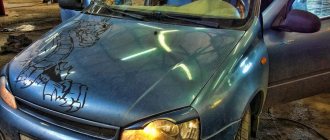
Viburnums on the front panel have a special yellow indicator, which, in the event of a breakdown of the electric amplifier, lights up and reports an error in the system. If it lights up, it means you have another reason to visit the nearest auto repair shop. But it’s immediately worth noting that the yellow indicator does not indicate a critical malfunction, but only signals the occurrence of a problem that allows you to drive the car, but without the participation of the ESD.
If the electric power steering has completely failed, it is better to stop immediately and pull out its fuses.
. In Kalina they are located on the left side of the steering wheel. Theoretically, in case of malfunctions, the EUR should turn off on its own. However, it doesn’t happen once at a time. Therefore, to be sure, it is still worth taking care of the fuses.
Operating principle
The basic principle of operation of the generator is as follows: a three-phase alternating current is induced in the stator winding, which is converted into direct current using a rectifier unit attached to the cover of the device. On the cover there is a unit consisting of an electronic voltage regulator and a brush holder. The rotor rotates from the crankshaft of the car engine via a serpentine belt.
The Lada Kalina generator has the following characteristics:
- maximum output current - 85-90 A;
- voltage - 14.4-15.1 V;
- engine-generator gear ratio - 1:2.4;
- direction of rotation is right.
4 bolts secure the stator and covers of the device. The covers contain bearings in which the rotor shaft rotates. The rear bearing is located on the rotor shaft; it is mounted in the rear cover with a small gap. The front bearing, which slides along the rotor shaft, is installed in the front cover with a slight interference fit and covered with a pressure plate. The device is covered at the back by a plastic casing.
The generator connection diagram is quite simple. When the car's ignition is turned on, voltage is supplied to the voltage regulator through the low battery warning light. When the engine is started, the field winding receives power from 3 diodes that are installed on the rectifier block.
Typically, checking the alternator is easily done using the battery charging warning light. If the device is working properly, this lamp should light up when the ignition is turned on, and when the engine starts, it should go out. If the lamp burns brightly or at full intensity, then the generator needs to be replaced or repaired because it is faulty.
Possible malfunctions and their causes
The main problem that causes breakdown of the electric power steering is a malfunction of the speed sensor.
The EUR installed on Kalina does not work with a constant force applied to the steering rack. The amplifier begins to operate at full strength only when the car is moving at low speed or is at rest. When accelerating, the power steering forces on the steering rack decrease. That is, the lower the speed, the more the power steering starts to work.
The naturally described malfunction can only be detected when the car is standing still or moving at low speed
.
This failure can only be corrected by completely replacing the speed sensor. Moreover, here it is not necessary to go to the service. You can replace everything yourself.
The second malfunction may be hidden in the EUR itself. Basically, it consists of self-disabling the electric power steering due to the fact that it has not passed self-test. That is, the device turns off automatically so as not to interfere with the driver when driving the car.
This kind of malfunction guarantees a trip to the service station and will require you to spend a lot of money.
Location of contacts on the blocks
Block X1: 1. “Plus” from the battery (12V); 2. “Minus” from the battery. Block X2: 1. Ignition switch (“plus” from the terminal); 2. Signal input (tachometer); 3. Signal input (speed sensor); 4. Output (EMURU status indicator); 5. K-line output (diagnostic block); 6. L-line output (free); 7. General (mass); 8. Technological output (free). Block X3: motor phases: A. (1 and 2) – phase A; B. (1 and 2) – B; C. (1 and 2) – C. Block X4: torque sensor ESD “Kalina”: 1. Common wire 1; 2. General 2; 3. Power contact; 4. Output 1; 5. Output 2; 6. Frequency signal input terminal. Block X5: rotor position sensor: 1. General; 2. Phase A output; 3. Phase B output; 4. Phase C output; 5. Power (+ 5V). The electromechanical power steering installed on the Kalina can operate in the following modes: • Self-test • Compensation • Failure • Ready
Additional reasons
Troubles in the operation of the electric power steering can be caused by:
- voltage drop due to possible circuit breaks due to wiring faults;
- exceeding the internal combustion engine speed;
- lack of speed sensor information.
In general, it is clear that there are not so many reasons why the ESD fails. Some of them are critical, some are not. But in any case, you need to take care of promptly eliminating the problem.
Today it is difficult to find reliable electrical circuits for an amplifier from a domestic car. Such information is mainly available only in services, and no one will share it with you. Therefore, repair of the electric power steering on Kalina is possible only within the walls of the service station
, since amateurism can be expensive. Here it is better not to take risks, not to be stingy, but to trust competent specialists.
About the principle of operation of a car generator
The operation of the Lada Kalina generator unit is based on the following principle: an alternating current is induced in the stator winding, which is subsequently transformed into direct current through a rectifier module located on the body of the unit. The generator cover is also equipped with an electronic voltage regulator and a brush holder. The rotor of the device receives torque from the crankshaft pulley. The transmission link is a poly V-belt.
The basic characteristics of the generator set include the following parameters:
- maximum generated current – 85-90 Amperes;
- operating range of on-board voltage – 14.4-15.1 Volts;
- rotation ratio of the motor and rotor – 1:2.4;
- right-hand direction of rotation.
The housing of the unit is held together by pins that tighten the stator with the covers. The mounting sockets of the indicated covers contain bearings, which ensure the ability of the rotor to rotate. The rear bearing is installed inside the cover with a minimum gap. The front element is equipped with the ability to slide along the surface of the rotor shaft. It is fixed inside the front cover with a slight interference fit, and a pressure plate covers it from the outside. The back of the device is protected by a plastic casing.
Let's move on to the switching diagram of the generator with the on-board network. The connection diagram is very simple. After turning on the ignition, power begins to flow to the voltage regulator through the battery discharge lamp circuit. When the motor starts, the excitation winding is supplied with supply voltage from three diodes mounted in the rectifier unit.
Using the indicated signal lamp, the generator unit can be checked. If the device is working properly, the lamp lights up when the ignition is on. It goes out when the engine starts. When this phenomenon is not observed and the lamp continues to shine, the generator set should be diagnosed for the presence of malfunctions. In some cases, replacement is required, and many are interested in how to remove the generator?
Reasons for shutdown
The main reason lies in the electric power steering
.
When ignited, the system performs a self-diagnosis and if the mechanism does not pass it, a signal is turned on indicating a malfunction. The color of the signal indicates the degree of danger. The light turns red, the problem needs to be fixed urgently. If the color is yellow, the vehicle can be operated, but safety precautions should be taken. Lada Kalina - Car Owners Blog: EUR does not work. reasons why steering
on Kalina work
- speed sensor malfunction;
- torque sensor malfunction;
- speed exceeds 60 km/h;
- engine speed is less than 400 per minute;
- failure in the control unit;
- poorly soldered contacts;
- insufficient tension.
What does Kalina's power steering consist of?
This unit is an independent device included in the steering mechanism of the Lada Kalina. It allows the driver to turn the steering wheel without much effort, and also ensures softness and smooth operation of the moving parts of the steering system.
Structurally, this mechanism cannot be classified as complex units. The electric power steering has the following parts:
- electric motor;
- gear unit;
- control module;
- sensors that monitor the torque, speed and number of revolutions made by the crankshaft.
The Lada Kalina on-board controller continuously monitors the functioning of this amplifier and controls its operation, but malfunctions do occur and many car owners are very interested in how to eliminate them. The mechanism is activated at engine speeds of 400 rpm. When the speed exceeds 60 km per hour, the electric booster stops functioning. This is done for the sake of safety, because at high speeds the driver must have confident feedback on the steering wheel, which a “light” steering wheel is not able to provide. With increasing speed, a gradual decrease in the magnitude of the force in the mechanism is observed.
Software shutdown
- The electric power steering
turns off after 60 km/h.
Therefore, keep this point in mind; it is set in the system unit and is not a breakdown. The Priora's electric power steering - Also, the EUR does not work at low engine speeds. If the value is less than 400 rpm, it is not active.
This is software planned inactivity. It is needed to give information to the steering wheel at high speed and reduce wear of the mechanism.
Electrical equipment Lada Kalina
If the voltage regulator unit, capacitor and not a tight fit of the brushes are faulty, or if they are worn out, the vehicle's supply voltage deviates from the norm. In this case, it is necessary to check the above listed elements and, if necessary, replace them. In this article we will talk in more detail about diagnosing and replacing generator elements in a Lada Kalina car.
To remove the Lada Kalina voltage regulator you will need the following tool:
flat-blade screwdriver, 8mm and 10mm open-end wrenches and 7mm, 8mm and 24mm socket wrenches, hammer, soldering iron, universal meter (with DC voltmeter and megger)
Checking the functionality of the voltage regulator on the Lada Kalina generator
1. Move aside the rubber insulating boot of the positive terminal from the generator. 2. Start the engine and allow the engine to warm up so that the vehicle operates normally at idle speed. 3. Measure the voltage between the positive terminal and the body (negative terminal). The voltage should be 14.5-15.1 volts.
If there is a deviation from the specified range, the voltage regulator must be replaced. See also checking the Lada Kalina generator regulator in the section “Replacing the voltage regulator”
Checking the functionality of the Lada Kalina generator capacitor
The capacitor is usually checked with a specialized meggometer, since not all universal devices have a measurement of up to 10 MoM. The device is set precisely in the range of 1-10 MΩ. Before connecting to the capacitor, the device shows infinity. If connected to a working capacitor, it begins to charge and an electric charge accumulates on its plates - current flows and, accordingly, the resistance on the device drops. After charging it (saturating the capacitor plates), the resistance again becomes infinite.
Replacing the voltage regulator Lada Kalina
carried out as follows
1. Disconnect the negative cable from the battery. 2. Disconnect the excitation block from the generator.
3. Disconnect the positive terminal from the battery by unscrewing the nut.
4. Remove the factory seal from one of the screws holding the plastic casing and remove the screws. Remove the protective plastic cover. 5. Remove the two screws securing the regulator and remove the voltage regulator.
6. Check the ease of movement of the brushes. They must protrude at least 5 mm from the voltage regulator housing. 7. You can check the voltage regulator by connecting a 12 V lamp to its outputs and applying a voltage in the range of up to 12 volts to its inputs, while the lamp should light and the voltage is more than 12 V to 16 V.
If the voltage is too high, the lamp should go out. If this algorithm does not work, then the regulator must be replaced. Installation of the regulator is done in the reverse order.
Replacing the rectifier unit with a capacitor Lada Kalina
1. Using a soldering iron, unsolder the six leads and remove the 3 bolts.
2. Remove the rectifier unit from the generator. Installation of the rectifier unit is carried out in the reverse order
Checking diodes on the rectifier block Lada Kalina
1. Dodas are checked with a universal device. (6 diodes in total) Attach the black “negative” probe to the negative plate, and the positive “red” probe alternately to the three contact terminals of the diodes. The resistance should be 580-620 Ohms.
Attach the red “positive” probe to the negative plate, and the negative “black” probe alternately to the three contact terminals of the diodes. The resistance should be 580-620 Ohms.
Checking the windings of the Lada Kalina generator
1. Check the generator windings with a device. All windings should have approximately equal resistance, without significant deviations. Deviations indicate a break or short circuit.
Electrical booster malfunctions
In the event that it is impossible to immediately check the cause of failure of the electric power steering on Kalina, you need to remove the fuse from the block. Why doesn't the electric power steering work? This is necessary to prevent sudden activation of the mechanism, which leads to emergency situations.
A direct indicator of a malfunction of the speed sensor in the electric power steering
Kalina, is a non-working speedometer, as well as an exclamation mark on the dashboard that lights up. It may not work for several reasons. Check the appearance of the sensor; if it is covered with dirt, simply clean it. See if any metal shavings have become magnetized and remove those as well.
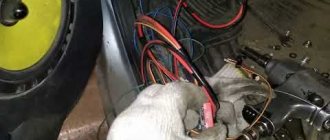
If this does not help, then the sensor is probably faulty. Such sensors are now inexpensive and can be found in many auto parts stores. We do the same for the torque sensor. But where is the speed sensor? It is usually located in the gearbox housing, see photo on the left.
Another cause of malfunction electric power steering is the generator. The control unit requires a voltage of 13.6 V to operate; if you have less, change the voltage regulator (chocolate) on it.
Types of generators
Based on current strength, generating devices for Kalina are available in the following types:
- 85 A.
- 90 A.
- 100 A.
- 115 A.
- 120 A.
- 135 A.
By power there are units:
- 12 V.
- 24 V.
The higher the performance characteristics of the device, the higher the price is set for it.
There are new units:
- New.
- Used.
New devices naturally cost more.
Generators for Kalina are produced by different manufacturers. So, you can buy a device from the company:
- ISKRA (Slovenia).
- LKD (China).
- BATE (Belarus).
- Eldix (Bulgaria).
- StartVOLT.
- KZATE.
- Pramo.
- Bosch.
Products from Eldix, Bosch, and BATE are more valued. Products from the Chinese company LKD are cheaper.
You can purchase a generator at the place of purchase:
The most expensive units are sold in specialized stores, the cheapest - in the car market and through advertisements.
Fuse box
The weak link of the electric power steering
on Kalina, is the fuse box, if something doesn’t
work , it’s worth checking them. To get to them, you need to open the dashboard, to the left of the steering wheel .
To do this, pull the top part towards you and the latch will open. Check if it works
fuse, if it fails, replace it. The one responsible for the operation of the electric power steering of the Lada Kalina Universal does not work. It is very easy to check, check the integrity of the thread inside the fuse. Changing a 50 amp relay to a 30 amp one will also help.
Newer versions of Kalina are equipped with electric amplifiers from Hyundai, which has a positive effect on its reliability. However, there are still thousands of cars with the domestic version, which malfunctions and breaks down from time to time. Now it will be easier for you to repair your electric power steering
on Kalina with your own hands. The main thing to remember is that not every amplifier shutdown is a breakdown. And you can find the problem yourself and fix it, but somewhere you will have to go to a service center.
Diagnostics
To check the amplifier in a car, you need to remove the plastic trim on the steering column; to do this, unscrew the bolts securing it from the bottom.
Then you will need to get to the 8-pin plug, its pinout is as follows:
- The blue contact is connected to the ignition switch, this is 12 volt power;
- the red-brown contact is the connection cable to the tachometer;
- the gray contact goes to the car speed controller;
- white and pink wire - amplifier control indicator;
- black-yellow contact is a diagnostic line;
- the next contact is empty, the wire is not connected to it;
- brown contact is ground;
- empty.
More accurate results will be obtained by checking the amplifier using a scanner. But since such equipment can usually only be found at service stations, you can try to check the operation of the system with a paper clip.
Let's sum it up
In a modern car, which can also be considered the Lada Kalina, most systems are equipped with sensors with the help of which the on-board module carries out control. If the check light is on, this indicates that a certain type of malfunction has occurred. The cause is found using a diagnostic device. Sometimes the problem when the check light is on requires the connection of more complex scanning equipment to identify the breakdown. In any case, to prevent malfunctions, it is necessary to perform regular diagnostic inspections, which will avoid premature failure of expensive components. Answering the question of how to reset a check, the answer is obvious: it is necessary to diagnose the malfunction and eliminate it.