Interesting things are happening in the Danish kingdom.
If anyone remembers, a month ago I fell through the ice. After which the car had certain problems with ignition. I had a problem with the starter and wanted to take it apart and check it. But after reading a little more, and also observing the behavior of the car, my doubts shifted a little towards the crankshaft position sensor. Yes, yes, the same sensor that is included in the mandatory spare parts, and without which the only thing the car will not be able to start.
In any case, the cost of verification is not that high. In addition, the BC has already shown error 053 “open circuit dpkv” a couple of times over the last month. So, in any case, it was necessary to buy in reserve.
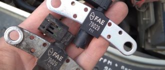
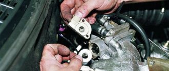
True, the attempt to buy this very sensor ran into the absence of the latter in the stores closest to me, of which one store is an official dealer :o( The sensor I had was Bosh. In the second they suggested that they have a complete analogue of this Bosh, from the Pegasus company , for GAZ cars. The price of the issue is 850 rubles versus 1,300 for the “native one.” The inspection showed the identity of the plug and the sensor was taken with the agreement to return it if it still does not fit.
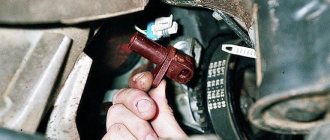
Next was lying under the car (access to the sensor from below) and a long struggle with the “10” bolt with which this sensor was screwed. Because it was screwed on so awkwardly that without a thin head and a small collar it was impossible to get to it, and I just don’t have them. Having raked all the keys out of the house for 10, the one I was looking for was finally found and the new sensor took its rightful place.
Turn the key and hooray! The car started up the first time.
Just in case, on the same day I still submitted the starter for maintenance. At which they disassembled the starter, cleaned it, drove it on a stand and gave a verdict - the starter is fine.
Yesterday I went to Kyshtym and Kasli. The car turned off ten times and started back up fine. I'm waiting for the cold weather to check how things are in such conditions.
BUT HERE'S THE MOST INTERESTING THING!
Having measured the consumption using BC (BC recently, consumption is now being measured under different conditions), I was amazed that consumption in the city dropped to 16 liters/100 km. Further measurements showed that after replacing the sensor, consumption in the city dropped from 18-22 l/100 km to 16-18 l. And driving in mixed mode highway/city (70/30) showed a consumption of 13.1 liters, although literally a week before I went to Miass and the consumption just on the highway was 13.5 liters. I haven’t had time to measure it purely on the highway yet. But preliminary conclusions are approximately the following - CONSUMPTION FALLED BY AN AVERAGE OF 3 L/100 KM. After replacing the sensor.
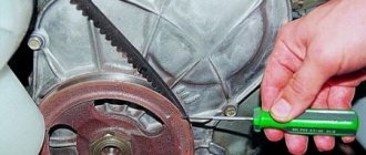
Why did the previous sensor malfunction and did it malfunction? I don't know, but I have a guess. There is a magnetic metal pin on the sensor, the distance from which to the synchronization disk should be 1 mm. On the new sensor, this pin sticks out from the body by 1-2 mm, but on the old one it is flush with the body and has a surface character that suggests that it was cut or erased by something. POSSIBLY, something actually erased it, increasing the gap between it and the synchronization disk, which could cause malfunctions. Those. The car either starts or doesn't start. In short, HELL KNOWS.
The design of the UAZ Patriot car has a large number of different sensors, without which it would be impossible to drive the SUV. The output of any of the sensors or regulators leads to the fact that one of the components or parts ceases to function, negatively affecting the vehicle system itself. Sensors are auxiliary elements involved in driving a UAZ Patriot car. This material will tell you about the control regulators on the UAZ Patriot SUV.
Oxygen sensor for UAZ Patriot: original, analogues, price, catalog items
During periodic operation of the vehicle, refueling with low-quality fuel, the controller(s) wear out and fail. A number of signs indicate a malfunction of the DCC, which we will look at below.
Because the sensor(s) are non-separable and cannot be prevented; replace them with new ones if necessary. The installation process of the DCC is not at all difficult, but it requires vigilance on the part of the repairman. Violation of regulations is unacceptable.
The upper DCC (control) is designed to determine the quantitative oxygen content in the exhaust gases of the cylinder combustion chamber.
The lower DCC (diagnostic) determines oxygen in the exhaust stream after passing through the catalytic filler. The data is transmitted to the electrical control unit, on the basis of which the ignition timing and the amount of air supplied to the combustion chamber are adjusted.
The excess of oxygen in consistency is called “enrichment”, and the reverse process is called “depletion”. Both factors have a negative effect on the functionality of the motor. This leads to a decrease in power, unstable idling, and increased fuel consumption.
In order to save money, many car enthusiasts receive low-quality spare parts, which accelerates the early wear of their equipment.
Main symptoms of DPKV malfunction
A faulty sensor or a faulty device sensor can be recognized by the following symptoms:
- The vehicle's propulsion system began to detonate. When the engine is idling or increasing engine speed, a knocking sound occurs from the hydraulic compensators. The so-called pins may knock when driving uphill at low engine speeds.
- The car engine is no longer as stable as before. The engine speed may drop sharply at idle or shift to a higher speed. A car can become stuck idling if it is stuck in traffic or at stop lights.
- The drive may not rotate at the correct speed even if it is running at maximum power.
- The machine's engine power may drop and then increase. In this case, the driver will not take any action.
- The aerodynamic properties and characteristics of the machine are significantly deteriorated.
- The generator may not start. The engine may not start or may catch fire and shut down suddenly.
- No spark when ignition. It may not appear at all or occur with a certain frequency.
If the vehicle owner detects three or more “symptoms” of an internal combustion engine malfunction, the device must be replaced.
It should be noted that the described malfunctions do not always indicate a controller malfunction. They may also indicate other problems with the drive. For example, a sharp change in engine power and a drop in speed indicates a clogged fuel pump or lines connected to it. Symptoms of incorrect operation of the combustion chamber may appear due to contamination of the sensor connection socket.
The Govorun4eg Auto channel showed signs of a faulty high pressure control valve in practice.
Signs of a malfunctioning oxygen sensor on a UAZ Patriot
The symptoms are identical to other breakdowns, so correctly identify the breakdown at the initial step.
- Difficulty starting the engine;
- Increased fuel consumption;
- Power reduction;
- Passive acceleration dynamics;
- The engine is not running properly;
- An indicator on the instrument panel indicates the presence of ECU system errors;
- Repeated lumbago is heard from the exhaust pipe, which indicates an enrichment (depletion) of the combustible mixture;
- Blue, gray, dark smoke from the exhaust pipe.
If you detect 1 or more signs, immediately contact a specialist 100 to carry out
Do-it-yourself controller diagnostics on UAZ Patriot
- We place the car above the inspection hole (roadside overpass);
- We remove the limit switches on one of the DCC;
- Connect the multimeter terminals;
- We activate the device in the “Resistance” position;
- We analyze the data;
- By analogy, we check the 2nd (diagnostic) DCC.
The arrow tends to infinity - the lambda probe is working, the arrow points to zero - damage. The controller is non-separable and cannot be prevented.
Along with measuring the resistance at the end switches, inspect the integrity of the insulating layer on the wiring. If there is damage, change sections of the cable.
Installing an oxygen sensor on a UAZ Patriot
- Key to "22";
- Flashlight;
- Diagnostic and control controllers.
- We install the UAZ Patriot over the inspection hole. We use a hydraulic lift if there is no hole;
- We turn off the engine, open the hood;
- We wait until the exhaust circuit cools down to a non-hazardous temperature, so as not to destroy the skin of the hands;
- From under the bottom we unclip the terminals on the diagnostic controller. We unscrew it, replace it with a new one, put on the block with wires;
- By analogy, we replace the control sensor.
DIY replacement completed. Subject to compliance with the regulations, the next maintenance is after 80 thousand km.
Visual inspection
Since the sensor installation is done with a gap adjustment, you first need to check this distance with a caliper. The next steps to check the crankshaft visually are:
- identification of third-party objects between it and the flywheel;
- presence of dirt in the place of missing teeth of the synchronization disk;
- wear or breakage of teeth (very rarely).
In principle, the car owner does not face any difficulties at this step. Subsequent testing must be done with devices, preferably a multimeter (tester), which can be switched to ohmmeter, voltmeter and ammeter mode.
Deep check
Before replacing the crankshaft sensor, a comprehensive inspection is recommended. The main criteria for its implementation are:
- room temperature (20 degrees);
- the presence of a transformer, meter, voltmeter, inductance meter and megger.
The check sequence looks like this:
- 500 V is supplied to the winding by the transformer;
- insulation resistance must be within 20 MΩ;
- The coil inductance is 200 - 400 mH.
If the indicated characteristics are within normal limits, and the Check error is displayed on the panel, then the cause of the malfunction lies in other components of the internal combustion engine. The signal is transmitted from the sensor without distortion. If any of the properties differ from the nominal value, the crankshaft position sensor needs to be replaced.
Optic
Structurally, this sensor is made of an LED and a receiver. The signal appears in the receiver when it passes through a section of the flywheel with ground teeth, since at this moment the LED beam is not blocked by the remaining intact teeth.
These simple actions do not allow the device to be used for any or additional operations. If a breakdown occurs (ignition desynchronization), the DPKV is replaced together with the wire.
How to check DPKV for performance?
You can check the operation of the DPKV in three ways:
Diagnostics of the crankshaft position sensor with an ohmmeter
You can use an ohmmeter to test the regulator winding to measure the resistance value. If an ohmmeter is not available, multimeters can be used. As a result of diagnostics, on a working sensor the resistance value should be in the range of 550-750 Ohms.
The testing process itself consists of measuring the resistance of the inductive regulator coil. If this equipment fails, the failure will affect the operating resistance parameter. Therefore, before starting the test, you should set the appropriate range and diagnose the correct operation of the device using measuring sensors.
The method of checking the crankshaft sensor with an ohmmeter is considered the simplest to perform, but does not give a 100% result.
Nikolay Vaganov demonstrated the procedure for diagnosing the crankshaft sensor using a multimeter.
Comprehensive diagnostics of the crankshaft position sensor
If there is any sign of a faulty crankshaft sensor, a sophisticated test method can be used. This diagnostic method is complex in execution, but more accurate. To manufacture it, you will need a set of devices and accessories that are not available at every service station.
To complete the task you will need:
- megohmmeter;
- a network conversion device that will be used to decode information;
- A traditional example of an inductance meter;
- Multimeter or digital voltmeter.
When conducting a comprehensive diagnosis of the crankshaft sensor, it is recommended to maintain the temperature within 20-22 degrees. This condition is necessary to ensure the correct values will be output by the device.
Features of complex device diagnostics:
- Using an ohmmeter or other tester, the operating resistance value is diagnosed.
- The amount of inductance is measured on the regulator winding by inductance. If the sensor The obtained value should be in the range of 250-400 mH.
- Then a procedure is carried out to measure the resistance of the insulating layer. When a voltage of 500 V is applied, the operating parameter value should be approximately 20 mOhm. A mains transformer will be required in case of periodic magnetization of the regulator. If the device is working properly, all values obtained from the test will be within the specified limits.
Diagnostics of the crankshaft position sensor signal using an oscilloscope
This diagnostic option is the most accurate of all those described. This is because not only the crankshaft element is checked, but also its design during engine operation. The essence of diagnostics is to connect an oscilloscope to the controller and monitor the signals using icons that extend from it. During the test, it is not necessary to disconnect the sensor from the drive, since all operations will be performed with the engine running.
- The wire with the black terminal connects to the vehicle's powertrain ground or ground.
- The bayonet probe is then installed on the signal pins of the controller itself. The connection occurs in parallel. To identify the output signal, the corresponding connector must be marked with the letter A.
- The next step is to connect the second probe of the diagnostic tool. The connector connects to the analog input via a computer or laptop. The software must be previously installed and configured on the other device.
- When all electrical circuits are connected correctly, the oscilloscope signal will appear on the computer screen. It will be plotted as a graph. The pulse voltage is set at the input of the controller being diagnosed.
- To diagnose the device, you must specify a special graph output mode. This mode is called inductive crankshaft. After setting all parameters, the installation starts. Then all controller parameters are monitored.
If a pulse is received from the controller that does not correspond to the nominal parameters, the generator will clearly twitch. It may be difficult to start the engine.
The appearance of such malfunctions when monitoring output pulses from the controller will indicate the following problems:
- defects in the controller design;
- damage to the element designed to interact with the synchronizer shaft;
- malfunctions in the functioning of the dentition.
Basic faults
Typically, for most on-board electrical appliances, certain symptoms of a crankshaft sensor malfunction are detected visually. For example, if the Check light comes on on the dashboard, the driver has a device to read the error code, the controller will show a count of 19 or 35.
Even more often there are other malfunctions:
- spontaneous engine shutdown;
- no start;
- critical operation of nozzles/injectors twice as often as the prescribed cycle (failure of the air flow control valve).
One of the methods available for self-diagnosis in this case is “diagnosis” with a tester. The internal resistance of the sensor winding should be within the range of 500 - 800 Ohms.
Repair may be required if the device is mechanically damaged. For example, if dirt or foreign objects get on the surface of the flywheel crown, the signal will be distorted by them.
The sync dial may accidentally become magnetized during diagnostics. In this case, the repair consists of demagnetization using a special technique using a 100-volt transformer.
READ Replacing the low beam lamp Mazda 6 gh
If the resistance of the coil winding does not correspond to the indicated characteristics, the owner of the car will usually find out about this by indirect signs:
How to quickly check the crankshaft position sensor synchronization UAZ Patriot
- revolutions jump randomly;
- the dynamics of movement are lost or the power of the internal combustion engine is lost;
- at idle speed “floats”;
- detonations occur during operation.
Attention: Since the indicated malfunctions may be caused by other reasons, it is better to visit 100 for computer diagnostics. In the latter case, you should check the crankshaft sensor using available methods.
Weaknesses of the ZMZ 409 engine
List of weak points of all modifications of ZMZ 409:
- Spark plug wires (armored wires);
- Crankshaft position sensor;
- Hydraulic timing chain tensioner;
- Thermostat;
- Ignition coils;
- Spark plug;
- Hydraulic compensators;
- Rear crankshaft oil seal;
- Idle air control sensor;
- Clutch slave cylinder;
- Water pump (pump);
- Vacuum brake booster;
- Cooling system pipes;
- Oxygen sensor;
- Accessory drive belt.
Read more about the weak points of the ZMZ 409 power unit
Armored wires. Characteristic frequent breakdowns of high-voltage wires are a common defect during operation. If insulation breakdowns did not happen on new cars, it would be excusable.
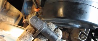
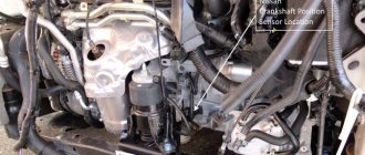
Crankshaft position sensor. The crankshaft sensor is located at the front of the engine on the right side of the camshaft gear cover flange. In order for it to work correctly, there must be a gap between the sensor and the teeth of the synchronization disk of 0.5-1.2 mm. The optimal gap is 0.8 mm. The cause of sensor failure (article 23.3847, analogue 23.3847) may be a mismatch in the size of the above gap or a malfunction in the electrical circuit (wiring). Symptoms of crankshaft sensor failure are as follows:
- The engine does not start, warm or cold, it makes no difference;
- Under load, detonation appears;
- The idle speed plays;
- Loss of power, stalls when applying gas;
- The speed changes spontaneously while driving.
Hydraulic timing chain tensioner. The hydraulic tensioner automatically compensates for timing chain wear. Its operation is ensured by the spring force, the cross-section of the check valve, the pressure oil pressure and the gap between the plunger and the tensioner body, designed structurally to ensure constant tension with optimal force without weakening or constriction. It is necessary to monitor the hydraulic chain tensioner, as it is unreliable. Otherwise, the timing chain breaks. Thank God that at least the valves don’t bend when it breaks.
Thermostat. Problematic thermostat, it fails even on new cars. As a rule, it freezes and is in the open state and does not regulate the thermal regime of the antifreeze. The culprit of the defect is an unfinished bypass valve.
Ignition coils. They burn when the gap on the spark plugs increases, as well as when the generator voltage regulator relay breaks down.
Spark plug . When buying a car, you need to check the gap in the spark plugs. Oddly enough, on new cars, spark plugs and everything connected with them fail precisely for this reason...
Hydraulic compensators. The knocking of hydraulic compensators is a consequence. Firstly, the reason lies in the quality of the oil, let’s say the wrong oil was originally poured in or it hasn’t been changed for a long time and it has lost its chemical properties. The symptom is a knocking noise when the engine is cold, but disappears when it warms up. If so, change the oil immediately. Secondly, the oil filter is clogged with secondary impurities, as a result of which the oil is not able to flow with the required pressure to the hydraulic compensators. In this case, a new filter must be installed. Thirdly, a worn oil pump is not able to provide oil pressure supplied to the hydraulic compensators.
Rear crankshaft oil seal. An oil leak from under the rear crankshaft bearing oil seal is no exception.
Idle air control sensor. Malfunction of the XX regulator sensor is a frequently recurring defect, usually due to wear on the guide needle or problems with the contacts inside the sensor.
Clutch slave cylinder. The clutch disappears due to the use of low-quality rubber products in the cylinder. The tightness is lost with the loss of hydraulic performance. Brake fluid may not leak; instead, air foam may appear in the fluid; you know how air pockets in the brake or clutch hydraulics affect their operation.
Purpose of the DPKV sensor
In the electric ignition systems of modern cars, the fuel mixture is injected into the cylinders and a spark is supplied from the spark plug after it is compressed by the on-board engine. The DPKV sensor is used to determine the spatial position of the pistons at each moment of time. This particular electrical device transmits a signal to the ECU to implement the designated sequence of actions by electrically igniting the car.
Regardless of what modification the crankshaft sensor is used, signs of malfunction of this device are expressed in the absence of a spark/fuel injection or a violation of this cycle. In other words, it is either impossible to start the internal combustion engine, or the engine stalls spontaneously after some time. This shows that the piston position signal at bottom and top dead center is distorted.
Less often, the wire connecting the DPKV with the ECU gets damaged; in this case, the signal does not enter the on-board vehicle, and the operation of the motor is impossible in principle.
How to replace DPKV?
To facilitate the disassembly and adjustment procedure or replacement of the controller, a 50-70 cm long wire is connected to it. This line is equipped with special key covers. To adjust the position of the controller, adjust the washer attached to the seat of the device. The procedure for adjusting this washer can be carried out in a workshop or at a service station. Correct adjustment will allow you to avoid rapid breakdown of the aggregate cylinders and reduce fuel consumption.
Algorithm of actions for exchanging controllers:
- The controller is disconnected from voltage; to do this, disconnect the plug using the device's wiring.
- Using a wrench, unscrew the screw that secures the device to the installation site.
- The driver himself has been dismantled.
- An undamaged controller must be placed in its place. The locking device is screwed back. The plug with wires is connected.
- After installing the controller, a gap measurement test must be performed. Pocket between the teeth of the generator drive command and check the regulator core. The TENTETTE kit is used to measure this parameter. The gap size should be between 0.39 and 0.41 mm, preferably 1 mm.
If diagnostics show that the clearance differs from the required value, adjust the position of the controller. Or you need to get rid of existing pollutants. After replacement, start the combustion engine and check for proper operation.
Good afternoon. In today's article, I have collected for you all the signs of a faulty crankshaft position sensor.
Traditionally for our site, the article contains many photos and video materials.
What is the crankshaft position sensor for and how does it work?
The crankshaft position sensor is used to determine the angle of rotation of the crankshaft at a given time.
This is the only sensor without which the engine will not work.
The crankshaft position sensor works in conjunction with a timing disc on a pulley or flywheel. The sync disk looks like this:
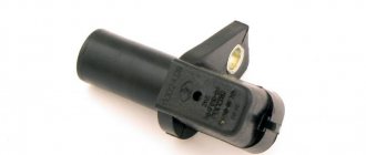
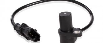
The crankshaft position sensor itself is a wire coil on a magnetic core.
When the synchronization disk rotates, the metal plates periodically approach and separate from the core, due to this the magnetic field strength changes, and an electric current is induced in the sensor coil.
If we connect the output signal of the sensor to an oscilloscope, we will see this picture:
This signal is sent to the engine control unit, and it in turn issues commands to supply a spark to the cylinders and open the injectors.
Although the sensor is a simple device, since it operates under difficult conditions (vibration, temperature changes), it sometimes fails. It is known that a sensor malfunction is not always obvious.
Signs of a malfunctioning crankshaft position sensor.
The engine does not start.
As already written above, DPKV is the only sensor without which the engine will not start.
If, when you turn the key in the ignition switch, the starter quickly turns the engine and the fuel pump hums, with a high degree of probability we can say that the problem is in the crankshaft position sensor.
The fact is that the engine control unit, not receiving a signal from this sensor, does not know in which cylinder to give a spark and in which to open the injector.
The sensor is checked using diagnostics or by replacing it with a known good one.
The engine suddenly stalls when hot.
This happens completely randomly. The engine warmed up to a certain temperature and stalled.
It stood and started up..... 5-10-20 minutes passed and everything started again.
The author of the article personally encountered such a manifestation of failure of the crankshaft position sensor.
Since I had the elm 327 diagnostic with me, I immediately understood what was wrong, but it was impossible to solve the problem, since there was still no spare sensor.....
After the car sat for 30 minutes it started as if nothing had happened.
As a result, we drove to the city, watering the sensor with water from a bottle every 10 minutes.
The cause of this malfunction is a microcrack in the sensor winding, which diverges due to thermal expansion.
The engine does not start in cold weather.
Design and principle of operation of the crankshaft sensor
So that the sensor can transmit a signal through a wire to the ECU microcontroller, the following principle is used:
- two flywheel teeth were deliberately omitted;
- when entire flywheel teeth rotate near the DPKV, they distort the magnetic field arising in the device coil;
- when a section of the crown with a missing tooth passes near the sensor, the interference disappears;
- the device transmits a signal about this to the computer, and the computer determines the precise position of the pistons in each cylinder.
Correct operation is only possible with a gap of 1 - 1.5 mm between the teeth of the flywheel ring and the electrode of the device. Therefore, there are adjusting washers above the DPKV mounting socket. And the 0.5 - 0.7 m long wire suitable from the ECU is equipped with a turnkey connector.
The ECU software allows you to calculate the position of the pistons in cylinders I and IV when a signal is received and the direction of shaft rotation. This is enough to correctly generate signals to the fuel supply and ignition sensor.
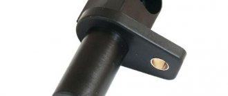
Engine crankshaft position sensor device
The crankshaft sensor consists of:
- Housing - plastic or aluminum with receptive part
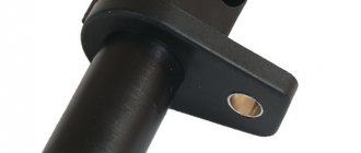
- Flange - oval with hole for M6 bolt
- Communication wire - shielded, 610 mm long
- The connecting plug of the wire is three-pin, crimped with the wire.
Sensory lobe - made of a magnetic core and a copper wire solenoid on an insulating reel
- The wire output of the domestic crankshaft position sensor is rotated 900 with respect to the line of the mounting hole.
- The wire outlet of the imported device is oriented in the other direction from the mounting hole.
Diagnosis of CPPV and DPRV
If there are interruptions in the operation of the internal combustion engine, there can be a huge number of circumstances. But despite the somewhat awkward placement, diagnosing the crankshaft sensor is a less labor-intensive process. crankshaft sensor can be replaced if the check reveals its malfunction. The principle of diagnosis is from simple to complex, in other words, visual inspection, then checking with an ohmmeter, then with an oscilloscope or on a computer.
Attention: To check the DPKV, it is recommended to dismantle it, so you should immediately mark its position relative to the body.
Knock sensor UAZ Patriot
Knock sensor 02612311046 manufactured by Bosch, either GT 305 or 18.3855 is installed on the engine cylinder block on the right side under the intake manifold in the area of the 4th cylinder.
Patriot knock sensor diagram : 1 – plug; 2 – insulator; 3 – body; 4 – nut; 5 – elastic washer; 6 – inertial washer; 7 – piezoelectric element; 8 – contact plate.
The knock sensor on the Patriot is a piezoelectric device that senses vibrations in the block wall caused by shock waves during detonation in the cylinders. Detonation is the explosive self-ignition of the working mixture in the engine cylinders. During detonation, voltage pulses are generated at the sensor output, which increase with increasing intensity of detonation impacts. The controller, based on the sensor signal, adjusts the ignition timing to eliminate fuel detonation flashes. If the sensor or its electrical circuits fail, the controller signals the driver by turning on the lamp and switches to a backup engine control mode with a late ignition timing. This mode is characterized by reduced engine power and increased fuel consumption, so the sensor must be replaced as soon as possible. To check, you need to remove the knock sensor from the car.
To remove and check the knock sensor you will need: a thin screwdriver or awl, a key number 13. Turn off the ignition and disconnect the wire from the negative terminal of the battery
Remove the heater hose from the holder on the sensor bolt. Disconnect the wiring harness connector from the sensor terminals by unfastening the spring lock of the block
Unscrew the nut, remove the heater hose bracket from the stud screwed into the wall of the cylinder head, and remove the sensor from the stud. Connect an autotester turned on in voltage measurement mode to the sensor terminals. Tap the sensor body with a hard object (for example, tweezers) - the voltage should change. If the voltage remains constant, the sensor is faulty and needs to be replaced. Install the UAZ knock sensor in the reverse order of removal.
Throttle position sensor UAZ Patriot
The throttle position sensor type 406.1130000-01 or DKG-1 0280122001 manufactured by Bosch is a potentiometer with a current-collecting element moving along the radius of the current-carrying sector from 0 to 100°. To check the Patriot throttle position sensor you will need: an auto tester and a screwdriver. Disconnect the wire from the negative terminal of the battery
Disconnect the wiring harness block from the sensor and measure the resistance between terminals “1” and “2” of the sensor block. For a working sensor it should be about 2 kOhm. Connect the autotester to pins “2” and “3”. When the throttle valve is open, the resistance should be 0.7–1.38 kOhm, when closed - 2.6 kOhm
To replace a faulty Patriot throttle position sensor, remove the two screws securing the sensor and remove the sensor . Install the new sensor in the reverse order of removal.