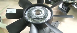
The cooling system of the UAZ Patriot engine contains an element called a “viscous coupling” or, as it is sometimes called, a “fluid coupling” - on which the fan is located. It is necessary to protect against overheating and is activated only when the engine temperature begins to exceed operating limits.
The viscous coupling on the UAZ Patriot is designed in such a way that it is connected to the engine crankshaft not directly, but through special disks, between which there is a working fluid. When starting a cold engine, the viscous coupling spins at a very low speed, much less than the number of engine revolutions.
Then, as the engine warms up, the metal plate in front of the viscous coupling heats up from the radiator and bends outward, which releases a special ball that closes the hole in the inner disk. It turns out that the working fluid has nowhere else to go and remains between the disks.
The working fluid used is a special one, so-called “dilatant”, based on silicone. When heated and stirred, it expands and becomes more like thick glue. Next, the fan speed increases to eventually equal the crankshaft speed. A serviceable clutch turns with little effort when the engine is turned off.
How to remove a fan pulley on a ZMZ 409
To cool the radiator, a fan is used, driven from the engine crankshaft through a special clutch.
Under prolonged loads and elevated air temperatures, the performance of the impeller is not enough to remove heat. Find out how to install an electric fan on a UAZ Patriot instead of a viscous coupling.
Installing an electric fan on the UAZ Patriot instead of a viscous coupling allows you to increase the air flow drawn through the radiator honeycombs and improve the temperature parameters of the power unit under conditions of increased load.
Advantages of an electric fan instead of a viscous coupling
Use an electric fan instead of a viscous coupling.
Advantages of using an electric drive for the radiator cooling impeller instead of a viscous coupling:
- ensuring the specified engine temperature regardless of the crankshaft speed;
- stable cooling of the power unit when idling (without moving or when moving at low speed);
- it is possible to force the electric motor to turn on using a toggle switch located in the car interior;
- It is allowed to install 2 fans (to increase the reliability of the design and improve airflow to the radiator).
The essence of the problem
The viscous coupling is a sealed housing filled with a viscous silicone-based working fluid. Inside the casing there are 2 disks with guide vanes; torque is transmitted by oil flows.
The characteristics of the liquid allow you to smoothly regulate the rotation speed of the output shaft and the fan impeller installed on it. The design ensures that the thermal regime of the motor is maintained at medium and high speeds.
When the engine speed drops to idle mode, the intensity of mixing of the working fluid in the clutch body decreases, which causes a decrease in the fan speed. A drop in air flow speed causes the radiator and engine jacket to overheat. The problem occurs when driving in long traffic jams or when driving on rough or swampy terrain at low speed.
An additional concern is the safety of the structure. In the center of the coupling there is a bimetallic plate that controls the bypass valve.
When the element is cooled (by the air flow from the radiator), the impeller rotates at low speed.
As the element warms up, the valve closes, and then the impeller accelerates sharply. At this point, there is a risk of injury to the driver servicing the engine. There have been cases of plastic impeller rupture (due to previous damage).
A few words about signs of malfunctions
There are very few such signs, but they exist, let's try to figure them out. Most manuals for car operation and repair advise checking how the fan rotates when the engine is cold and hot. It is also stated there that on a cold engine no significant changes in the rotation speed are noticeable during throttling, but on a hot engine, on the contrary, it increases.
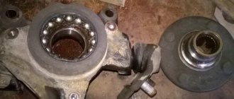
The longitudinal play of the clutch fan should be checked; if it is present, it requires treatment. The appearance of extraneous noise during rotation may indicate bearing failure. Malfunctions also include aging of sealing seals. However, the most common type of malfunction is leakage of silicone fluid from the coupling body.
Viscous cooling fan coupling: where it is located and how it works
The fan rotation speed changes smoothly, steplessly; a fan with a viscous coupling never turns on and off instantly
In all-wheel drive transmissions of passenger vehicles with a longitudinal engine position, a standard viscous coupling performs the functions of an ersatz differential or a special locking element that complements a conventional differential. However, from a design point of view, the device is represented by a plurality of round driving and driven plate elements with projections and holes, which are located inside a completely waterproof housing filled with dilatant liquid.
The fan rotation speed depends on the heating of the engine: the more the viscous coupling is heated, the more the inlet channel opens, and the more liquid enters the working chamber.
In the absence or insignificant volume of automobile oil inside the working chamber, free rotation of the drive disk is observed. Only in the process of gradual warming up of the engine and increasing the temperature of the antifreeze does the bimetallic plate heat up and expand, which causes the opening of the intake valve system, penetration of the working fluid into the chamber and an increase in the speed of rotational movements of the ventilating impeller. As the adhesion coefficient decreases, the difference in the rotational speed of the housing and the viscous coupling drive shaft increases noticeably, which slows down the operation of the fan impeller.
Operating principle of viscous coupling
The operation of a viscous coupling is based on simple principles, one of which is contained in its name: the transmission of torque from the rotor to the housing is ensured by the viscosity of the working fluid. And the clutch control is provided by two sensitive elements - a bimetallic spiral spring and a bimetallic plate. When the temperature changes, the bimetallic spring unwinds and twists, ensuring rotation of the bimetallic plate attached to the pin. In turn, the bimetallic plate bends or straightens when the temperature changes, opening and closing the channels.
When the engine is cold (immediately after starting), the viscous coupling is at a low temperature, the spring is at its minimum length, the bimetal plate is pressed against the index plate, and the intake ports are closed. In this case, the clutch rotor rotates freely and, due to centrifugal forces and teeth at the end, holds the working fluid in the reservoir. Thus, the working chambers remain empty, and the torque from the rotor is not transmitted to the housing. Although in this case the fan rotates at a low speed, since there is some friction in the bearings.
When the engine heats up, the clutch also heats up due to the incoming air flow blown through the radiator. When heated, the bimetallic spring unwinds and rotates the bimetallic plate, which moves and opens one inlet channel - the working fluid enters the front working chamber. Due to the viscosity of the liquid, “viscous friction” occurs between the rotor and the plate, the torque is partially transmitted from the rotor to the housing, and the fan begins to rotate. The fan rotation speed depends on the heating of the engine, since the more the viscous coupling is heated, the more the inlet channel opens, and the more liquid enters the working chamber.
When the engine heats up significantly, the bimetallic plate bends, as a result of which the second inlet channel opens, through which the working fluid enters the second working chamber, the friction forces between the rotor and the dividing plates increase, and the torque is transmitted to the fan impeller with minimal losses. When the intake ducts are opened to maximum, the fan rotates at approximately the same speed as the water pump pulley.
When the engine cools, reverse processes occur: first, the bimetallic plate returns to its original position, closing one intake channel, and then the plate rotates and closes the second channel.
After the engine is completely stopped, the working fluid flows into the lower part of the tanks and working chambers, which is a certain problem: when the engine is subsequently started, the working fluid will not be able to immediately leave the working chambers, the fan will begin to rotate, which will interfere with normal warming up of the engine. This problem is solved by the presence of a large volume rear tank, which is located just below the level of the working chambers. When the engine is stopped, the working fluid flows into this reservoir and practically does not occupy the volume of the working chambers, therefore, when the engine is subsequently started, the fan will rotate at a low speed, without interfering with warming up.
Today, special silicone-based compounds are used as working fluids. Such compositions have an interesting effect (called dilatant) - their viscosity increases sharply at high shear strain rates. That is, while in the reservoir, such a liquid behaves like a regular lubricant, but as soon as it gets into the working chamber between the moving plates, its viscosity increases. It was this property of dilatant liquids that made the very existence of viscous couplings possible.
Specifically, in hydraulic couplings of domestic and most foreign cars, a special polymethylsiloxane fluid PMS-10000 (TU 6-02-737-78) is used. This liquid is sold, so it is possible to carry out independent repairs and maintenance of viscous couplings.
Thus, the viscous clutch operates automatically, providing a change in fan speed depending on changes in engine temperature, without resorting to complex sensors, without wasting electricity, and without requiring driver intervention. This is very convenient and effective, which led to the widespread use of viscous couplings on UAZ vehicles.
How to check a viscous coupling (using the example of UAZ Patriot)
The engine cooling system of the UAZ Patriot is equipped with a standard viscous coupling with a fan. This device provides reliable protection against overheating by turning on when the engine temperature goes beyond the established operating parameters. The viscous coupling does not have a rigid connection to the crankshaft, and starting a cold engine causes it to rotate at low speed.
It is very difficult to independently diagnose a breakdown of a viscous coupling in normal mode, but there are several ways to easily verify the functionality of such a device. To check the viscous coupling of the UAZ Patriot cooling fan, you should take a closer look at the speed of the mechanism when the engine is turned on, cold and warm.
Completion of assembly
After installing all the timing parts and the cylinder head cover, all that remains is to mount the previously removed components: crankshaft sensor, pump, alternator belt, power steering belt, fan pulley, oil sump and radiator. After assembly, fill in oil and antifreeze. Connect the high-voltage wires and connect the negative wire to the battery terminal.
Removing the fan and viscous coupling
• Remove the fan casing To do this, use a small screwdriver to remove the pins of the spacer clips in the upper part of the casing, remove both clips, and then lift the casing upwards.
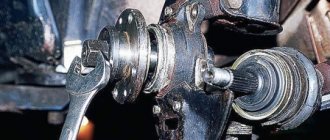
• Unscrew the nut securing the fan to the water pump hub using a 32 mm open-end wrench.
Attention: the nut has a left-hand thread, so it must turn to the right.
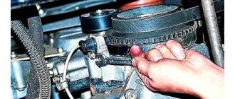
• When loosening the nut, press on the water pump drive belt to keep the hub from turning. If the nut does not budge, hit the lock handle with a suitable hammer to loosen it. You can then unscrew the nut by rotating the fan impeller. Be careful not to drop the fan.
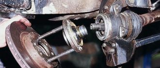
• If necessary, remove the viscous coupling. by unscrewing the four mounting bolts (indicated by arrows).
A viscous coupling is a mechanical device that transmits torque using a special viscous fluid. Knowing how to check the viscous coupling of a cooling fan, it is quite possible to independently determine the reason for its incorrect functioning, and then decide on the feasibility and scope of repair work.
About the electric fan
The electric fan covers all the disadvantages that the viscous coupling had. After installing it, it will be difficult not to notice the following improvements:
From the factory, on a UAZ Patriot with air conditioning, a so-called “sparka” is installed in front of the air conditioner radiator (on the street side) - two electric fans in a plastic case. But they have little effect on the main radiator, and besides, they make a lot of noise. Therefore, if you have already decided to install electric fans instead of a viscous coupling, you can safely remove them.
Installation process
To install an electric fan, it is not at all necessary to visit a service center; everything can be done independently at home. First of all, it is necessary to select or manufacture a base for electric fans (frame or “screen”) that matches the size of the engine cooling radiator.
Pros and cons of viscous coupling
Let's start with the disadvantages, because it is because of them that owners prefer to install electric fans on the UAZ Patriot instead of a viscous coupling. And the most significant disadvantage, perhaps, is poor engine airflow at low speeds - for example, in traffic jams or when driving over rough terrain at low speed. After all, the efficiency of a viscous coupling directly depends on these very revolutions.
Besides this, there are other disadvantages:
- Additional load on the engine. The viscous coupling takes away part of the engine power, this is especially noticeable when overtaking on the highway, when the operating speed is almost in the red zone of the tachometer. Acoustic comfort also suffers - a characteristic noise and howl appears.
- There is no way to force the fan to turn on at full power, for example, in the same traffic jams.
- The clutch makes it difficult to access the idler rollers and drive belts, which significantly complicates and increases the time spent on repairs.
- There is a danger of fan blades coming off at high speeds, as well as the risk of damage to the main radiator from flying fan fragments, which may require expensive repairs with a complete replacement of antifreeze/antifreeze. Now imagine that this could happen on the highway, somewhere far from home.
- Cannot be repaired. The faulty clutch is replaced with a new one, although you can try drilling a few holes and fixing it with bolts so that it always rotates. But this repair method is only suitable for summer; in winter, the engine will take a very long time to warm up.
- A simple and fairly reliable design that can work for years without any maintenance.
- It is installed on the UAZ Patriot from the factory, so you will not have to modify anything if it is replaced.
- Does not create a load on the electrical part of the car.
As you can see, the viscous coupling has more disadvantages, so many Patriot owners eventually come to the idea of replacing it with electric fans.
DIY troubleshooting
Standard disassembly of a viscous coupling involves removing the device, dismantling the impeller, unscrewing a pair of mounting pins, draining the working fluid, thoroughly washing the inside with gasoline and drying it. After filling with new PMS-10000 silicone oil, the device is mounted back.
To troubleshoot a viscous coupling or replace it, you must first remove the device:
- Remove the fan casing by removing the pins and spacer clips.
To make the key fit, its ends can be sharpened with a grinder
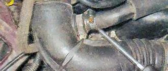
You need to press the belt between the temple pulley and the power steering pulley
Insert the key from above between the two blades
If the cause of incorrect operation of the viscous coupling is a leak of silicone liquid from the base, then the following actions are performed:
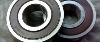
If there is a variety of unusual noise in the cooling radiator, the bearing will need to be replaced. For this purpose, it is necessary to drain the oil and disassemble the assembly using a special puller. After installing the new bearing, the device is mounted in the reverse order, after which new silicone fluid is poured.
A special automotive device - a viscous coupling that rotates the cooling fan using liquid - quite often fails. It is possible to fix only the simplest breakdowns on your own, so in the most difficult cases you need to contact a service center with auto mechanics who specialize in working with these types of devices.
Preparing to replace the timing belt
The presence of two chains in the gas distribution mechanism, the top one and one of them, makes the process of repairing the gas distribution mechanism quite labor-intensive. There is an option to replace the UAZ Patriot timing belt at home only if you have an equipped room for repairs and the ability of a mechanic.
To complete the work you will need:
- Timing belt repair kit: levers, sprockets, chains, dampers, gaskets.
- Thread locker and gasket sealant
- A little fresh motor oil
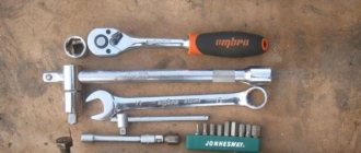
Required tools:
- Hex key 6 mm
- Wrench set (10 to 17)
- Driver and heads for 12, 13, 14
- Hammer, screwdriver, chisel
- Tool for setting valve timing
- Additional accessories (a container for draining antifreeze from radiators, a jack, a gear puller, etc.)
Before the change itself, position the car so that you have access to the engine compartment from all sides, including from below. Turn off the ignition and remove the negative wire from the battery terminal. If you set a goal to gain access specifically to the gas distribution mechanism of the ZMZ-409 engine, you will first have to dismantle several components located differently on the engine near it.
First, you need to drain the engine oil and antifreeze into suitable containers, then there is the option to remove
radiator.
Partially unscrew the oil crankcase bolts or completely dismantle the crankcase - this will make it easier to install the gas distribution mechanism in the near future. Next, remove drive belt
and additionally remove the fan pulley.
Next, remove the drive belt for the generator and water pump. After disconnecting the supply hose from the pump, you need to remove the cylinder head cover. Disconnect the high-voltage wires, unscrew the four bolts and remove the front cylinder head cover along with the fan. Then, unscrew the three bolts and disconnect the pump. Remove the crankshaft position sensor from its socket in the cylinder block by unscrewing the bolt securing it. Remove the crankshaft pulley. Experienced mechanics advise raising the engine with a jack to make removing this part easier.
Electric Fan Installation
Replacing viscous couplings with electric fans begins with purchasing or making your own metal support frame for electric motors, which is then placed on the inside of the radiator.
On some vehicles equipped with an air conditioning system, an additional air conditioning heat exchanger with electric fans (installed on the outside of the radiator) is used. It is not recommended to remove the elements as they are controlled by the air conditioning controller to keep the air inside the vehicle cool.
For cooling, 2 fans from the Gazelle or from the “classic” VAZ models are used. When purchasing an impeller, you should consider the direction of air flow created by the blades. Additionally, it is necessary to replace the sensor in the thermostat housing, which activates the operation of the electric motors.
There are several types of sensors that are triggered at a liquid temperature of +87...+97°C. An additional toggle switch for manually turning on the engines is located in the car interior (on the dashboard or center console between the seats).
It is allowed to use fan units from Nissan X-Trail SUVs, which are equipped with a 4-channel patch cable. The devices are connected to the power unit control controller and to a temperature sensor (with a response threshold increased to +95...+97°C).
Installing an electric fan is very simple.
The signal from the control unit turns on the impellers with an operating capacity of 40% of the maximum value. With a further increase in temperature, a sensor located in the thermostat housing is triggered, allowing the fans to be switched to maximum air supply.
There have been cases of using a fan from Hover (catalog number 1308100K00V1), which is equipped with additional resistance to obtain 2 speeds of rotation of the impeller. The product is supplied with a plastic frame, which is installed on the UAZ Patriot radiator with minor modifications.
Before installation, you will need to cut down 2 support brackets, which are placed on the lower edge of the plastic diffuser. For mounting, standard holes on the radiator are used, intended for installing the original guide casing.
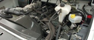
The design of the cooling system of UAZ cars
All engines used in cars of the Ulyanovsk Automobile Plant are equipped with a classic liquid water cooling system. The system is divided into two circuits - small and large. The large circuit includes the water jacket in the block and the cylinder head, the heater radiator and the engine cooling radiator, the thermostat and the pipe system, the small circuit includes everything except the cooling radiator. The circuits are separated by a thermostat, which, depending on the coolant temperature, either opens or closes the inlet to the radiator.
However, the cooling system of UAZ engines also has some peculiarities. For example, shutters are installed in front of the radiator (behind the radiator grille), which allow the driver to regulate the flow of air passing through the radiator. The blinds are controlled from the cabin using a special handle; they allow you to regulate the engine temperature within a fairly wide range depending on the outside air temperature.
Also, the UMZ and ZMZ engines installed on UAZ vehicles use three main types of cooling fan drives:
• Permanent drive; • Drive through a fluid coupling (also known as viscous coupling and viscous coupling); • Drive via electromagnetic clutch.
Engines with permanent fan drive have not been produced for a long time; such a system was used on early modifications of the UAZ-31512 (UAZ-469B) and some other models. However, already in the 20th century, the old ZMZ-402 and UMZ-417 engines began to be equipped with a viscous coupling, and today almost all engines installed on UAZ vehicles have a hydraulic coupling for the fan drive. Motors with electromagnetic couplings have become somewhat widespread, although they have not yet become as popular as the fluid coupling. Also, UAZ vehicles use an electric fan drive (from an electric motor) to a limited extent, but this is most often a makeshift solution.
The viscous coupling plays an important role in the engine cooling system, so let’s look at this part in more detail.
Installing an electric fan on a UAZ Bukhanka
The clutch allows you to reduce fuel consumption, reduce fan noise, and promotes better warm-up of a cold engine.
The viscous clutch is removed if it malfunctions, if the clutch does not turn on or does not turn on completely.
You will need a 32 key.
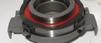
View of the viscous coupling assembled with the fan
To make it easier to unscrew the coupling, unscrew one pin
Unscrew the coupling shaft from the fan drive hub
Please note that the connection between the coupling and the hub has a left-hand thread
Remove the viscous coupling assembly with the fan
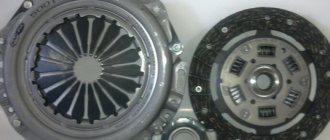
Unscrew the four nuts securing the fan to the coupling
Remove the fan from the coupling
Install the fan and clutch in reverse order
UAZ Patriot - viscous coupling replacement
In the UAZ Patriot there is an element called a “viscous coupling” or, as it is sometimes called, a “fluid coupling” - on which the fan is located. It is needed to protect against overheating and is activated only in this case, when the motor temperature begins to go beyond the operating limits.
The viscous coupling on the UAZ Patriot is designed in such a way that it is connected to the engine crankshaft not directly, but through special disks, between which there is a working fluid. When starting a cool engine, the viscous coupling rotates at a very low speed, even lower than the number of engine revolutions.
Then, as the engine warms up, the iron plate in the front part of the viscous coupling heats up from the radiator and bends outward, which releases a special ball that closes the hole in the inner disk. It turns out that the working water has nowhere else to go and remains between the disks.
Timing assembly
Having completed the disassembly of the timing belt, it is necessary to change what remains for our client to make the worn timing belt parts new. Chains and gears must be treated with engine oil before installation. During assembly, great attention should be paid to the correct installation of the timing gears, because this affects the correct operation of the engine. If gear 1 was removed from the crankshaft, then it must be pressed back, then put on the O-ring and insert the bushing. Orient the crankshaft so that the marks on the gear and M2 on the cylinder block coincide. With the crankshaft in the correct position, the piston of the first cylinder will take the top dead center (TDC) position. Secure the lower damper 17 without shelving the bolts for now. Hook chain 4 onto gear 1, then insert gear 5 into the chain. Gear 5 must be put on the intermediate shaft so that the pin of the gear coincides with the hole in the shaft. The M1 mark will be opposite the corresponding mark on the cylinder block. Insert gear 6 with a pin into the hole on gear 5. Using 2 bolts, secure the gears and the locking plate. Bend the plate on the sides, firmly fixing the bolts. Press the lower hydraulic tensioner lever. Marks on the cylinder block
and gears when tensioning the chain are made to match correctly.
Now there is an option to completely secure the chain guide 17. Thread the upper chain into the hole in the cylinder head and hook it to gear 6. Then insert gear 14 into the chain. Place gear 14 onto the exhaust camshaft. To achieve this, the shaft must first be turned slightly clockwise. After making sure that pin 11 fits into the gear hole, secure it with a bolt. Now turn the camshaft in the opposite direction until the gear mark coincides with the upper surface of the cylinder head 15. The remaining gears should be motionless. Putting the chain on gear 10, secure it in the same way. Fix the chain tension by installing dampers 15 and 16. Remove the power steering pump drive belt and the fan pulley from the crankshaft pulley (see “Replacing the power steering pump drive belt and the viscous clutch of the fan drive of the accounting cooling program complex”). 4.5. Remove drive belt (see “Replacing the generator and water pump drive
”).3.
Unscrew the 6 bolts securing the pulley. Then attach the pulley to the crankshaft. Tighten the pulley mounting bolt by shifting the gearbox to fifth gear and raising the handbrake. Afterwards, rotate the crankshaft by hand until the piston of the first cylinder reaches the TDC position. Once again, make sure that the marks on the gears (1, 5, 12 and 14) on the cylinder block
. Place the front cylinder head cover in place.
Service
Maintenance of power units of all types for the “Loaf” is given in the same way. All these engines were developed on the basis of the legendary ZMZ 402, and therefore the maintenance for them is approximately the same.
For representatives of UMZ 417 and 421, engine maintenance is carried out almost similarly. Thus, scheduled maintenance is carried out every 15,000 km. Maintenance includes changing the oil and filter. To change the oil, you will have to unscrew the drain plug and wait for the lubricant to drain. Then, the plug is screwed in and oil is poured through the filler neck. The oil filter is changed when there is no oil in the engine.
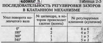
Maintenance also includes checking all systems for oil leaks and malfunctions. Every 30,000 km the valves must be adjusted, and every 20,000 km the air filter element must be replaced.
The essence of the problem
Let's start with the fact that the engineer of the Ulyanovsk Automobile Plant equips UAZ Patriot SUVs with radiator cooling fans, which are driven by a viscous coupling.
A viscous coupling is a mechanism presented in the form of two flat disks. Viscous coupling allows you to transmit torque using a special silicone-based fluid.
The operating principle consists of several plates mounted on the driven and drive shafts. They rotate in a container with liquid, which changes its properties when heated. When the liquid is mixed while the drive shaft rotates, it changes its properties (expands) and thereby creates pressure in the chamber. As a result, the disks of the driven shaft engage, causing it to move.
The device of the fluid coupling (viscous coupling) of the UAZ fan drive
UAZ vehicles use viscous couplings with a two-stage control system. Such couplings have a slightly more complex design than single-chamber viscous couplings of earlier releases, but they provide better fan performance and prevent some negative effects. Couplings of different models have a fundamentally identical design, differing only in some details. Therefore, we will consider here the general structure of the viscous coupling of UAZ cars.
The basis of the coupling consists of two parts: the housing and the rotor located inside it. The rotor is installed inside the housing through bearings on the rotor shaft; the shaft itself goes into a flange, with the help of which the fisc coupling is mounted on the water pump pulley. The rotor divides the internal space of the housing into two cavities, which, in turn, are also divided into two chambers by special plates (intermediate washers, they are rigidly connected to the housing). As a result, four cavities are formed inside the coupling: two working chambers located on both sides of the rotor, and two reservoirs located on the opposite sides of the plates.
On the side of the working chambers, the rotor and washers are equipped with annular ribs, which greatly increase the surface area of the chambers and increase the efficiency of the coupling. In essence, working chambers are “labyrinths” of cavities in which working fluid circulates. This solution makes it possible to abandon the use of a package of friction discs and simplify the design of the viscous coupling.
The front washer has four inlet channels located on opposite sides. One channel on each side is connected to the front working chamber, the second - to the rear working chamber. Moreover, windows are made in the rotor to supply liquid to the rear working chamber. In the coupling body or between the front plate and the body there are bypass (return) channels that supply fluid from the working chambers to the front reservoir.
The inlet channels are closed with a wide bimetallic plate, which is pressed against the front washer. A pin is passed through the center of the front wall of the coupling body, which holds the bimetallic plate, and on the outside is connected to a spiral bimetallic spring. The bimetallic spring is rigidly connected to the bimetallic plate through a pin, and the plate together with the pin can rotate through a certain angle, opening or closing the inlet channels.
However, when the bimetallic plate is rotated, only one of the inlet channels opens; the second channel opens at a higher temperature due to the bending of the bimetallic plate. Thus, the inlet channels and the bimetallic plate form a valve system that opens and closes depending on the temperature of the coupling.
At the end of the rotor there are oblique teeth (rim gear), which play the role of a pump for pumping working fluid from the working chambers to the front reservoir.
The coupling body is usually made of aluminum alloy, which has high thermal conductivity. On the outside, the housing has fins that increase the surface area of the coupling. Both of these solutions are aimed at reducing the thermal inertia of the viscous coupling - thanks to the heat-conducting material and a developed system of fins, the coupling heats up and cools down faster, ensuring a change in fan speed with minimal lag behind changes in engine temperature.
In the front part of the coupling body there are studs for mounting the impeller, and the studs also cover the holes through which the working fluid is poured into the fluid coupling cavity. Viscous couplings assembled with an impeller are also on sale. Sometimes it makes sense to buy just such a coupling, since today in UAZs plastic fans are more often used, and their service life is noticeably lower than that of metal fans of the old design.
Key for removing viscous coupling on UAZ Patriot ZMZ 409
Key for removing viscous coupling on UAZ Patriot ZMZ 409
Post by lexmak » May 28, 2022, 02:51 pm
Any factory key for 32 with a thickness of no more than 9 mm. Found in nature.
Well, that's all.
Key for removing viscous coupling on UAZ Patriot ZMZ 409
Post by igorstrong » 06 Jun 2022, 07:30
Key for removing viscous coupling on UAZ Patriot ZMZ 409
Post by lexmak » 06 Jun 2022, 17:49