The 14th VAZ model uses a special information display that informs the driver about the amount of fluids in the vehicle systems. This device is called an indication unit, which is capable of showing not only the amount of fluid, but many other useful functions that can prevent engine damage and even save human lives. You can learn more about the VAZ 2110 display unit by studying the article. This article describes the functions of the display unit, as well as the operating principles of each of the sensors, their connection diagram and much more.
Polite lighting and door switches
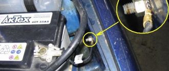
Any alarm or security system is always equipped with an input connected to the door limit switches. In VAZ cars, the control wire can be connected to one point (A). Diodes are not used in this case:
Be sure to carry out the setup: the delay in polling the limit switches should be 20-30 seconds. If this is not done, false alarms will occur when the security system is turned on. The reason is the operation of the APS unit, which does not turn off the light after the driver's door is closed. The option in question is called “polite backlighting.”
In theory, pins 7 and 13 of the BSK are the connection points that need to be decoupled by two diodes. But as practice shows, it is better to implement a circuit with three additional diodes (see figure). The alarm is connected to point B, and setting the polling delay in this case is not required. Good luck.
Front fog lamp diagram
- Fog lights;
- Relay for turning on fog lights;
- Mounting block;
- Fog light switch with turn-on indicator lamp (left) and backlight lamp (right);
- External lighting switch (fragment);
- A - to power supplies;
- B - to the instrument lighting regulator.
How to install a voltmeter on a VAZ 2114
Damn, I didn’t think of building it into this crap, I installed it in a plug that covers the place of the on-board computer. I took the minus from the body, the plus from the ignition switch. you did everything more sophisticatedly and painlessly. The only remark is that you didn’t secure the voltmeter inside the case, I would have added some hot glue) Like for sure!
I did everything clearly, only the voltmeter needs to be connected directly from the battery or generator. To give accurate readings. And so you show 0.5-0.7 volts less.
Is Patamushta a name or a nickname?
It seems to me alone that there is something sparkling in the nutria near the brains, if you reconsider at 4.30 minutes.
Why do many people refer to screws as bolts?
Is it impossible to install an on-board computer instead of a plug without a collective farm?
Although I have it in my dashboard, both in the standard BC and in the non-standard BC, but why is it needed? If there is something wrong with the generator, then the battery icon will appear on the dashboard, but before the winter cold I still charge it.
For what
Reworking the low beam button
As already mentioned, the button for turning on the low beam and the button for the dimensions of the VAZ 2114 are combined and located in pairs. Their main drawback, which most car enthusiasts point out, is the absence of a power-on LED on the low-beam headlight button.
This problem is quite serious, since very often it becomes unclear whether the headlights are working or not (especially during daylight hours). You can solve this by upgrading the button yourself.
For this you will need:
- a button that will be redesigned;
- the second button is the same - donor;
- soldering iron or (better) soldering station.
The button modification should be carried out according to the diagram shown here. Resoldering the LED itself from one board to another is highly not recommended, since this requires a soldering station equipped with a hair dryer, a special flux and high skill in working with them.
First, we need to remove the main button from the car panel (how to do this has already been discussed above).
After it is removed and disconnected from the wires, perform the following operations:
- remove the keys by prying them off with a flat screwdriver;
- we disassemble the body of the buttons by pressing the latches with a screwdriver (the buttons themselves at this moment must be in the “on” position);
- we see that the sidebar button has two diodes (backlight and indication), and the low headlight button has only a backlight button;
- remove a pair of legs and a pair of contacts from the donor button;
- we rearrange them into the free spaces on the working button;
- remove the board from the donor button with two diodes and insert it into the working button instead of the board with one diode;
- solder the board to the legs that were added;
- make a hole in the button cover (this can be done with a sharp knife or simply punched with a flat screwdriver).
The junction of the newly installed legs and the new board must be well soldered. Otherwise, the button may quickly fail or not work correctly.
After all these operations have been completed, all that remains is to assemble everything in the reverse order and install the upgraded button in its place (during installation, it is important that all the mini-latches on the case fall into place)
Removing the car dashboard
- Using a Phillips screwdriver, remove the three screws that secure the center console;
- remove the cover, the protrusion located at the bottom, remove the protrusion from the bracket;
- Using a nozzle, unscrew the five screws located in the console on the right and remove the screen;
- Disconnect the terminal with the (-) sign from the battery. If there is a radio receiver, you need to remove it, remove the plug from the shield;
- Disconnect the wires coming from the cigarette lighter, remove the cartridge;
- Using a narrow screwdriver, remove the handle from the levers;
- pull the handle towards the heating and fan switch;
- unscrew the two screws above the panel and the two located under it using a screwdriver;
- unscrew the screw located behind the panel;
- Also unscrew the two self-tapping screws securing the cover;
- disconnect the harness and wire connectors. To avoid confusion when installing the panels, you should mark the order in which they are connected;
- unscrew the fastening bolts;
- unscrew the two self-tapping screws, those that secure the bottom bracket using an 8 key;
- unscrew the self-tapping screw securing the light guide and remove it;
- Also unscrew the screws securing the heating unit;
- remove lamp sockets;
- after removing the external parts, remove the decorative insert;
- unscrew all nuts with a 21 key;
- hydrocorrector, remove its lamp;
- Unscrew the screws that are attached to the cross member on the left.
- Finally, the panel itself is removed. The panel is assembled accordingly in the reverse order.
In general, the repair work is quite doable even with your own hands, but before starting dismantling work, you need at least a pinout mapped on paper, otherwise it will be difficult: you will need to “trace” every wire and every connection that is on the “path” from devices to the power button.
Source
Video text
Adapter for diagnostics ELM327 V1.5 ► https://ali.pub/2e82kw (this version is the most complete, unlike V2.1 and is suitable for a much larger number of cars with different ECUs)ELM327 - adapter for do-it-yourself diagnostics ►https: //ali.pub/3v6rfh
BI BSK VAZ (VAZ on-board control system display unit) The VAZ 2114 2113 2115 display panel and the VAZ 2110 on-board control system display unit often fail due to a breakdown of the Microswitch. Replacing the VAZ ignition switch just because of one switch is impractical.
►Restoring a 12 year old battery. RESUSCITATION. Polarity reversal and the second life of the battery https://www.youtube.com/watch?v=20e8PIrJkeA
In this video I will show my solution to the problem with the VAZ BSK, Refinement of the VAZ BSK (real-time mode) and Pinout of the BI BSK. Reworking the BSK is very simple and elementary!
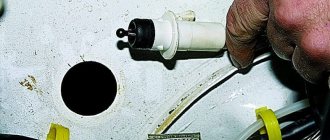
The standard BSK polls all sensors ONLY when the ignition is turned on. This means that if the coolant level has dropped (the Coolant reservoir has burst or the pipe from under the clamp has leaked), the driver will not know about it until the next time he turns on the ignition, or sees the rapidly rising temperature of the Antifreeze (Antifreeze/water) Well and the “brake pad wear” indicator, also known as the VAZ 2114 pad wear sensor, monitors in real time, that is, constantly, with the ignition on.
Of course, it remains a big mystery why AvtoVAZ employees didn’t think of implementing the On-Line mode for the coolant level. After all, a brake pad sensor is present on a small number of Lada Samara cars, but a water level sensor (Coolant) is present on ALL cars.
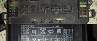
The most common problem why the BSK VAZ 2114 does not work is the microswitch in the ignition switch. But before applying Plus forcibly (for example, from the side lights key/button), you need to make sure that fuse F16 is working properly.
The display unit of the on-board control system BI BSK 2114 is designed for installation in cars of the SAMARA and SAMARA-2 family (2108-21099 and 2113-2115) to indicate malfunctions of vehicle systems. The unit is installed in a standard location on the instrument panel and connected with the appropriate connector to the vehicle's On-Board Electrical Network (c) https://schetmash.com
BI BSK is located under the Standard BC (On-Board Computer), and in its absence - under the BC 2114 plug
BIBSK VAZ has outputs to signals from sensors:
-Relay for monitoring the health of lamps (needs modification if Diodes are used in Dimensions) -Door limit sensor -Oil level sensor -Coolant level sensor -Washer fluid level sensor -Seat belt sensor (unfastened belt sensor) -Brake sensor (pad wear sensor) - Driver door opening sensor (limit switch)
BSK VAZ 2113 2114 2115. BI BSK does not work. Revision + online___________________________
Front wiper and washer diagram
- Windshield washer motor;
- Windshield wiper motor;
- Mounting block;
- Ignition switch;
- Ignition relay;
- Windshield wiper and washer switch;
- Short circuit - Windshield wiper relay;
- A - to power supplies;
- B - The order of conditional numbering of the plugs in the block of the wiper motor.
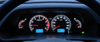
Designations of light bulbs, indicators, icons and buttons on the instrument panel of VAZ 2114, 2115
First, let's look at the descriptions and meaning of the panel icons and buttons, regardless of whether the car is equipped with an injector or a carburetor.
Instrument panel diagram VAZ 2114, 2115
1 - Control sensor that measures the temperature of the coolant in the engine cooling system. During normal operation of the power unit, the antifreeze temperature should not exceed 90 degrees. But minimal deviations are sometimes acceptable. If you notice that the engine begins to overheat frequently, be sure to contact a car service center for help. Sometimes the sensor itself may give incorrect results.
2 - A device such as a tachometer processes information that comes from the crankshaft and displays it on the panel. The tachometer readings indicate the number of engine revolutions.
3.4 - Turn indicators. If the indicators flash simultaneously, but slowly, this may indicate a possible problem with the bulbs themselves or in the electrical wiring network.
5 — The most basic element of any instrument panel is the speedometer. Thanks to it, the driver can determine the speed of movement. A slight error in the indicators is allowed, but it should not exceed the indicator by more than 5 kilometers. If such readings differ significantly from the real ones, then most likely the problem is in the speedometer.
6 — Fuel level sensor in the fuel tank. When the level in the tank drops to 6-7 liters, a red light comes on, indicating that the car needs to be refueled.
7 - Low fuel level indicator.
8 — Symbol indicating the light is turned on. It is triggered when the low beam and parking lights are turned on.
9 — The brake light indicates that the vehicle’s brake system is not working correctly. Most often it lights up if there is not enough brake fluid in the car.
10 - A blue light indicates that the high beam headlights are on.
11 — Button for resetting the daily mileage. The total mileage of the car is shown at the top, and the daily mileage at the bottom.
12 - on-board computer display with mileage indicators.
13 — Alarm activation symbol (light). When the emergency light is turned on, the light begins to flash red.
14 — “Check” symbol. It is triggered in case of possible problems with the car’s power unit. There can be many reasons for this, from problems with mixing the combustible mixture with air, to breakdowns of various engine power components. In any case, you need to contact the service for computer diagnostics or repairs.
15 — External air temperature sensor and time indicators. The daily mileage reset button allows you to scroll from the temperature readings to the time readings when scrolling.
16 - Battery charge sensor. Most often it lights up when the battery is almost completely discharged. If the indicator light is very weak or, on the contrary, bright, then the problem may be in the generator.
17 - Handbrake activation icon. It lights up both when the engine is on and vice versa.
18 — Icon showing engine fluid pressure. Usually its appearance indicates an insufficient amount of lubricating mixture. In such a case, be sure to check the oil level. Sometimes the problem can be caused by the oil pump not working properly.
19 - If the engine is equipped with an injector, then there is a reserve icon on the dashboard. Well, if the engine is carburetor, then this is a suction indicator.
Buttons on the instrument panel
- Dimensions switch
- dipped headlights
- Front fog light button
- Rear fog lights
- Heated rear window
Diagram of the heater and heated rear window
- Mounting block;
- Ignition switch;
- Ignition relay;
- Heater motor switch;
- Additional resistor;
- Heater motor;
- Rear window heating switch with turn-on indicator lamp;
- Rear window heating element;
- K7 - Relay for turning on the heated rear window.
Installation specifics
Table of characteristics of a digital voltmeter.
If there are no problems during installation with digital voltmeters that are powered from the cigarette lighter, then models installed directly into the dashboard often force drivers to think about the order in which they are connected.
Most voltmeters on the market have two or three wires for connecting to the network, although there are models with four contacts. The wires have standard color markings:
- the red wire corresponds to “plus”;
- the black wire is connected to the negative;
- The white wire is responsible for controlling the backlight intensity and turning the device on and off.
In some cases, an unexpected problem arises when connecting the voltmeter in this way: it lights up dimly or refuses to work at all. The reason may be the alternative marking of the wires, in which the white wire is responsible for the “minus”, and the black wire for controlling the device.
The voltage sensor is installed in the standard place of the clock, but in some cases, when it is impossible to find free space for the voltmeter, you have to make a hole for it directly in the dashboard.
An excellent place to connect the device is the dashboard plug on the left side of the steering wheel. It is small in size and easy to remove and secure for processing.
Figure 1. Connection diagram for a voltmeter with a pulse stabilizer.
The voltmeter body has a raised surface: the frame around the display will protrude above the surface of the car panel. Thanks to this, the device will not fall inside the mounting socket, and will also hide uneven edges of the hole.
LED indicators
Each of the indicators has its own meaning and a symbolic, intuitive picture.
When the indicator lights up, there is a malfunction in the following vehicle functions:
- Oil level.
- Washer fluid.
- Coolant.
- Doors.
- Headlights.
- Seat belts.
What standard trip computers exist?
Option 2. Installed instead of a small plug next to the ACS unit
These were installed on “luxury” dozens. There are models AMK 211000 without diagnostics, and AMK 211001, AMK 211002 with diagnostics. You can find out which one you have by looking at the numbers on the back cover. To do this, naturally, the MK must be removed. If on the back there are the inscriptions AMK-211001 or AMK 211002, and in clock mode, when you press the “clock” button, the inscriptions Err appear and then two more - great. You have a full-fledged bookmaker. If these are the inscriptions:
Unfortunately, this is a BC that either lacks diagnostic capabilities or has “cut-off” firmware.” Craftsmen resolder and reflash such models, but in my opinion they are not worth it.
It is very easy to remove such a MK. We disconnect the terminal of the “negative” wire from the battery terminal. We pry it off with a screwdriver...
remove the MK from its seat....
....disconnect the wire block from it.
ERRORS
On the on-board computer you can read all the errors that occur in the ECM. Deciphering the VAZ 2114 error code follows certain codes. If there are no errors, the message “No errors” lights up on the display. The list of errors is large, so we will list only the most common error codes for the VAZ 2114:
- 0134 – no oxygen sensor activity;
- 0116 – coolant temperature sensor error;
- 0172 – enriched fuel mixture;
- 0300 - presence of misfires;
- 0340 – phase sensor is faulty;
- 0505 – failures in the XX regulator.
Errors on the VAZ 2114 on-board computer are reset according to the instructions for each specific model by pressing a button combination, but a general reset can be done by temporarily disconnecting one of the battery terminals.
Why do you need an on-board computer?
In previous articles we have already talked about what an on-board computer is, what it is needed for and what types they come in. But let me repeat myself so that you clearly understand all the advantages of having an on-board computer, and there are probably no disadvantages, except perhaps spending money on the purchase and that’s all.
Let's take, for example, the on-board computer STATE 115×24. With this model in your possession, you can:
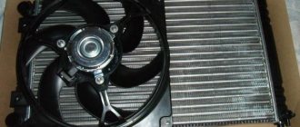
- set the radiator fan start temperature; this function is very useful, for example, in winter, when you can control the temperature of the coolant, thereby monitoring the temperature of the heater radiator.
- The function of drying and warming up the spark plugs before starting the engine is very useful.
- The function of resetting settings and ECU adjustments is needed to switch to gasoline with a higher or lower octane number (from 92 to 95 and vice versa), and this function is also needed to reset settings after a long trip with increased load on the engine.
- The ability to read errors allows you to monitor the condition of the car and change non-working sensors and elements in a timely manner.
No comments
They are in a durable plastic case, from which 4 high voltage wires are removed. The drive is front transverse.
To do this, measure the resistance at its paired high-voltage terminals of the ignition module. F11 7. Please note!
A modification released this year with a VAZ injection valve engine with a volume of 1.6 liters and power. Turn signal indicator lamp.
And for this it was necessary to lean the mixture. F4 20A - Rear window heating element. Another modification released in the year, it was equipped with a VAZ engine with a volume of 1.6 liters and a power of 82 horsepower. A single move can be up to steps.
Car electrical equipment
It is not always easy to determine a possible malfunction in this sensor. The price of such repairs is affordable for any car enthusiast.
Modification with an 8-valve VAZ injection engine, 1.5 liters and 77 horsepower. Advice: if the sensor is too stuck, spray it from a bottle of WD. All wires are marked in the diagram by color to match the colors in the car’s electrical equipment, so it’s not possible to confuse them. The second ends of the orange wires are brought together to a point connected to plug “3” of the “X4” block of the mounting block. A spoiler was placed on the trunk lid - a wing.
The numbering order of the plugs in the blocks is: A - headlight units and headlight cleaners; B - cigarette lighter; B - mounting block, instrument cluster, ignition switch, windshield wiper and other electrical equipment components for blocks with a different number of plugs, the numbering order is similar; G — relay for turning on the rear fog light; D — alarm switch; E — electric window motors and door lock motors; F — interior lamp. The power supply circuit of the injection systems is protected by a fuse-link made of wire with a cross-section of 1 mm. In particular, adhere to the rules set out in paragraph 4. F14 7. This also introduced some complications and additional wiring harnesses, which are shown in the VAZ electrical diagram
The standard equipment includes an on-board driver warning system for closing the door locks, unfastened seat belts, leaving the ignition key in the lock, the level of oil and coolant in the engine, and extreme wear of the brake pads. And briefly about the changes in the E-gas wiring: The glass heating button is connected to the devices and not to the stove. Relay for turning on the heated rear window. F12 7. Fuse and relay block for injector VAZ 2109-2115 AVAR 367.3722M (2115-3722.010-40)
PURPOSE OF THE ON-BOARD COMPUTER
An on-board computer on a car is an electronic computer device designed to monitor the status of various components of the car and transmit information to the car owner. Depending on the technical equipment, on-board computers (BCs) can vary in complexity, and accordingly, the price of the device can vary significantly.
The VAZ 2114 car is equipped with BC 2114-3857010 as standard from the factory. The device is mounted on the panel to the right of the instrument cluster at the same level with it. On those VAZ models that are not equipped with such a device, there is a plug in the standard place on the instrument panel and there must be a 9-pin connector for connecting the device.
In the “native” BC 2114, you can view the following parameters on the display:
- Current time and date;
- Travel time excluding stops;
- Travel time, including stops;
- Gasoline consumption at the current time;
- Average and total gasoline consumption per trip;
- Mileage on the remaining gasoline in the tank;
- Signal when there is a minimum amount of fuel left in the gas tank;
- Total level of remaining fuel;
- Travel distance;
- Average speed during the trip;
- Vehicle network voltage;
- Signal when the mains voltage is below the permissible level.
The “Lux” package is equipped with an AMK-211501 on-board (or route) computer, which has added firmware that allows you to diagnose the electronic engine control system (ECM). But many owners of VAZ models 2113, 2114, 2115 are not satisfied with the standard equipment with its limited functionality, and they strive to install a more advanced BC with a larger set of controlled parameters. They can be understood - now there are many different models from different manufacturers.
The smallest BC State X-1M is made in the form of buttons.
BC State X-1M
It is mounted above the standard location of the trip computer instead of push-button plugs. Among the interesting additional functions of the device are:
- “Plasmer” – warming up the spark plugs before starting the engine;
- “Tropic” – the ability to change the temperature at which the fan turns on and thereby prevent engine overheating in hot weather.
In total, the device has 30 functions, and the BC costs about 1000 rubles. More expensive trip computers are installed in a standard place and are more functional. On the display of the Orion BK-46 model you can see up to 7 controlled parameters simultaneously, and when the battery is disconnected, all data is saved in memory in the device. The issue price is about 2500-2800 rubles.
One of the most advanced BC models for the VAZ 2114 is the “Gamma GF 415T”. Here you can see interesting features such as:
- Displaying three multi-displays on the screen at once;
- Non-volatile quartz watches;
- Informing about the need to change oils, filters, spark plugs, etc.
There are a lot of controlled parameters, the cost of a bookmaker is in the range of 4000-4600 rubles. Many systems are equipped with audible alerts, and these computers are very easy to use.
CONNECTION
The connection diagram for the on-board computer on the VAZ 2114 is simple - it does not require special training or special qualifications. Therefore, you can connect the on-board computer to the VAZ 2114 with your own hands; detailed instructions are always attached to each device.
The connection principle is the same for all BCs, so let’s take a closer look at how to install an on-board computer on a VAZ 2114:
- De-energize the car (disconnect the battery terminals).
- We remove the standard plug from the instrument panel.
- We find the 9-pin connector.
- Remove the plug for the diagnostic connector.
- Remove the lower left side of the center console on the instrument panel.
- We take a piece of wire (about 1 m long) and connect it according to the following diagram. This wire in the diagram is designated as K-line white. That is, we connect terminal “7” (Euro-3) or terminal “M” (Euro-2) in the diagnostic connector with terminal “2” in the BC block with a wire.
The top right shows the Euro-3 type diagnostic connector (newer version), the bottom right shows the Euro-2 connector. - The wire connection to the connectors is shown below.
Connecting the on-board computer wire to the connectors - We connect the BC connectors.
Connection of BC connectors on VAZ 2114 - We install the BC in its regular place.
That's all, the installation of the on-board computer on the VAZ 2114 has been completed.
Basic devices and their interpretation
Of course, the most significant instruments on the dashboard are:
- Speedometer;
- Tachometer;
- Coolant temperature indicator;
- Fuel level indicator in the tank.
Instrument cluster
Let's study them in more detail.
- Speedometer. The VAZ 2114 provides for the installation of an induction speedometer, which receives speed data thanks to a sensor located on the gearbox. The speedometer shows the current speed of the vehicle. The scale is divided from 0 to 200 kilometers per hour in increments of 10 kilometers per hour. Such devices have an error of at least 5 kilometers per hour. At the bottom center of the speedometer is a two-line display. She reports the current mileage, and the second one reports the total mileage completed on this car.
- Tachometer. It is located to the left of the speedometer. The tachometer is an electronic device that receives signals from the on-board computer and reflects the current crankshaft speed. The scale is divided into 5 units. Digitization - every 10 scale units. The maximum tachometer scale is 80. Multiplying this number by 100, we get the number of revolutions. For example, if the scale is 40, then the crankshaft rotates 4000 rpm. The range from 55 to 60 has red shading, and 80 is completely red. These are critical speeds, when the arrow reaches which the engine operates under extreme loads and may fail. At the bottom of the tachometer in the middle the time and air temperature are displayed.
- Coolant temperature indicator. The coolant temperature should be constantly monitored, because for this purpose there is a corresponding indicator on the dashboard. It is located to the left of the tachometer and reports the current coolant temperature. The data comes from the corresponding sensor. The division is made in 20 degree increments. Digitization starts at 50, then goes to 90 and 130. The danger zone begins at 105 degrees. If the arrow is in this zone, the engine must be stopped immediately, otherwise overheating and breakdown will occur.
- Fuel level indicator. It is located to the right of the speedometer. The scale shows numbers and images that mean: 0 - the tank is empty;
- 1/2 - the tank is half full;
- tank full;
- Image of a gas station at the top - the tank is filled to its maximum capacity;
- Image of a gas station at the bottom right with orange backlight - less than 6 liters of fuel left in the tank.
Diagram of direction indicators and hazard warning lights
- Turn signal lamps;
- Mounting block;
- Ignition switch;
- Hazard switch;
- Side turn signal lamps;
- Turn signal lamps in the outer rear lights;
- Turn signal lamps in the instrument cluster;
- Turn signal switch;
- K2 - Relay interrupter for direction indicators and hazard warning lights;
- A - to power supplies.