After the active introduction of an injection power system on various VAZ models, the overall design of the car became more complex. As you know, an injector, unlike a carburetor, cannot dose fuel itself. To solve the problem, control of the fuel injectors was transferred to the electronic engine control unit (ECU) or controller, better known as a computer or “brains”.
On the one hand, by installing the brains in the VAZ, the manufacturer made the engine more economical and less toxic. However, on the other hand, the control system has become more complex, and a large number of additional solutions and devices have appeared. Next, we will look at what features the VAZ electronic unit has, where it is located on different models, what functions the ECU performs, etc.
How to independently replace an electronic engine control unit (ECU, ECM, controller)
The electronic engine control system detects failures associated with wire breaks, short circuits to each other or to ground.
With poor contact quality in the connectors. And also with a malfunction of the sensors themselves. However, there are malfunctions in the power and ignition systems that have external signs (which are noticed by the driver), but no fault codes are recorded in the memory of the electronic unit. Main symptoms of malfunctions:
If, when starting the engine, the battery voltage drops to eight volts (determined by the voltmeter on the instrument panel), then these are poor starting conditions (low ambient temperature) or the battery capacity is less than nominal. Quite often, a voltage drop is associated with oxidation of the battery terminals. Also, starting the engine will be difficult at low temperatures and high oil viscosity.
— jerks or failures in engine operation.
When you press the gas pedal, there is no expected acceleration. A well-warmed-up engine should, when you sharply press the gas pedal, increase the crankshaft speed from low (800-900 rpm) to high (5000 rpm) in no more than 0.75 seconds.
— insufficient throttle response (power).
When the car is moving, downshifts are often used. The speed is picking up slowly. There is a feeling that the engine “does not pull, it’s dull.”
The following elements of the electronic system may be associated with the appearance of this symptom: mass air flow sensor, oxygen sensor, clogged injectors, unbalanced injectors, lack of required fuel pressure due to a malfunction of the fuel pump or pressure regulator. You should check whether the throttle valve opens fully and whether the exhaust system is clogged.
- frequent detonation.
A sharp metallic knock is heard, changing when the throttle valve is opened. The main factors contributing to the occurrence of detonation are temperature and pressure in the combustion chamber. As well as the ignition timing.
The following elements of the electronic system may be associated with the appearance of this symptom: mass air flow sensor, coolant temperature sensor, oxygen sensor, knock sensor, lack of required fuel pressure due to a malfunction of the fuel pump or pressure regulator.
The air filter should be replaced. If the filter is heavily contaminated, the correspondence between the action on the gas pedal and the signal from the mass air flow sensor sent to the control unit is disrupted.
— delays, twitching, failures.
This is most noticeable when starting off.
When you press the gas pedal, the engine does not immediately respond by increasing the crankshaft speed. Such delays can occur at all vehicle speeds.
The following elements of the electronic system may be associated with the appearance of this symptom: mass air flow sensor, throttle position sensor, injector imbalance, lack of required fuel pressure due to a malfunction of the fuel pump or pressure regulator, malfunctions in the ignition module (high-voltage wires, spark plug tips, etc.) the spark plugs themselves are faulty, the high-voltage terminals of the ignition coils are heavily oxidized).
— interruptions in engine operation.
Uneven engine operation. When the crankshaft rotation speed changes, jerking begins, especially when the load increases. There is a constant popping noise in the muffler at idle.
The correct operation of the same sensor can be disrupted by magnetization of the toothed synchronization disk (checked with a thin steel plate).
The following elements of the electronic system may be associated with the appearance of this symptom: imbalance of injectors, lack of required fuel pressure due to a malfunction of the fuel pump or pressure regulator.
- increased fuel consumption.
Tire pressure is below normal, a malfunction of the brake system (braking of one or more wheels), an aggressive driving style, all malfunctions in the engine, power and ignition systems, malfunctions in the cooling system.
— Unstable engine operation, stopping at idle.
Air leaks behind the mass air flow sensor, improper operation of the idle air control.
— pungent smell of gasoline in the exhaust system.
This phenomenon usually occurs when the working mixture is very rich, and the enrichment is associated with a misfire. It is also not recommended to idle the engine for long periods of time.
Operating principle of the controller (ECU)
Throughout the entire operation of the engine, the electronic engine control unit receives, processes, and controls systems and sensors that affect both engine operation and secondary engine elements (exhaust system). The controller uses data from the following sensors:
- DPKV (Crankshaft Position Sensor).
- DF (Phase sensor).
- MAF (instant air flow sensor).
- DTOZH (Coolant temperature sensor).
- TPS (Throttle Position Sensor).
- DK (oxygen sensor).
- DD (Knock Sensor).
- DS (Speed Sensor).
- And other sensors.
Receiving data from the sources listed above, the ECU controls the operation of the following sensors and systems:
- Fuel system (Fuel pump, pressure regulator, injectors).
- Ignition system.
- Idle speed regulator (IAC, IAC).
- Adsorber.
- Radiator fan.
- Self-diagnosis system.
Also, the ECM (ecu) has three types of memory:
- Programmable read-only memory (PROM); Contains the so-called firmware, i.e. a program containing the main calibration readings and engine control algorithm. This memory is not erased when the power is turned off and is permanent. Amenable to reprogramming and chip tuning.
- Random Access Memory (RAM); It is a temporary memory in which system errors and measured parameters are stored. This memory is erased when the power is turned off.
- Electrically reprogrammable memory device (EPROM). This type of memory can be said to be the protection of the car. It temporarily stores codes and passwords for the vehicle's anti-theft system. The immobilizer and EEPROM are compared with data, after which the engine can be started.
Description of "brains"
The VAZ 2110 is considered the first vehicle in the domestic automobile industry equipped with an injection engine. The power unit is controlled by an ECU, an electronic device that determines the basic parameters of engine operation in accordance with sensor signals. In fact, the ECU of a VAZ 2110, VAZ 2112 or any other model is the “brains” of the car, the operation of which affects the functionality of the vehicle as a whole.
Control controller in VAZ 2110
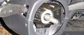
In the “Tens”, as well as the VAZ 2112, there are 16 valves and other models equipped with BOSCH 7.9.7 or January 7.2 systems, one M6 screw is installed in the head. From this screw the mass is taken to the ignition coils, and the mass is taken directly to the control model in the cabin. Typically, the mass is a welded stud mounted on the ECM bracket, particularly behind the center console, behind the left screen. In this case, the mass is transferred to the bracket through a pin, which is welded on the engine shield in the middle. It should also be noted that the nut on this stud is not usually tightened.
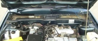
Control unit location
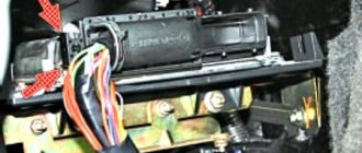
Now let's consider the location of the VAZ 2110 ECU. This device in the Ten is located under the center console, in its lower part, in particular, under the control panel. In order to gain access to the control module, you must remove the plastic panel on the passenger side, to do this you will have to use a Phillips screwdriver. Once you remove the cover, you will see many different wires, plugs, and safety devices. The controller itself is located behind them, it is screwed to the bar in a horizontal position.
The arrow indicates the location of the ECM module behind the center console
Typical malfunctions: their symptoms and causes
If the electronic engine management system malfunctions, this can lead to problems with the operation of the power unit. Unfortunately, ECU malfunctions in dozens of domestic cars are not uncommon, so the car owner should be aware of the main problems, as well as the reasons for their occurrence.
First, let's look at the symptoms of malfunctions:
As for the reasons, malfunctions in the electronic control unit can occur as a result of:
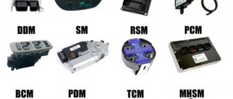
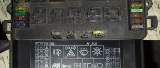
Pinout of contacts on the controller
Error P0504
This malfunction is associated with an incorrect signal from the brake pedal switches. Most often, the cause of such a failure is a malfunction of the brake pedal position sensor, lack of proper adjustment, or a broken spring that is installed in this device. Procedure for checking and troubleshooting:
- We remove the sensor;
- Move the rod lock to the right position using a screwdriver;
- We use a multimeter with an ohmmeter function;
- On Largus, Vesta and Xray cars, contacts 3-4 should be closed and have a resistance close to zero. Contacts 1-2 are open and their resistance should tend to infinity.
- When you press the rod on contacts 3-4, the circuit opens, and on contacts 1-2 it closes. If this is not the case, then the sensor must be replaced.
- On Priora, Kalina, Granta, Niva cars, contacts 1-4 should be closed, and 2-3 open. When you press the rod, the situation is the opposite.
- Before reinstalling the sensor, move the rod to the left position.
Sensor locations in video:
Adjusting the brake pedal position sensor:
Any driver can carry out this procedure at home without a trip to a service station. The part has two nuts in its design. One of them is on top, and the second is on the bottom. The upper nut adjusts the pressure of the rod. First you need to release the lower one, and then tighten the upper one, thereby changing the gap of the element. You need to ensure that the rod is fully pressed and not partially pressed. After this, start the car and let it run for about 10 minutes to check if the error appears.
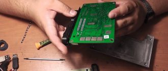
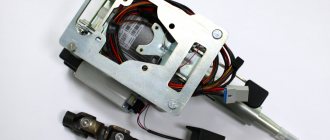
Instructions for removing and replacing the computer
The need to dismantle the ECM unit 16 of the ten valve engine arises if repairs are necessary when faults are identified. The repair process itself will depend on what exactly happened in the operation of the ECU. For example, if the contacts on the module connector have oxidized, the unit must be dismantled to clean or replace them. If the reason lies in damage to the housing, then the device must be removed for replacement; if water has gotten inside, then the module should be removed in order to dry it. Only after you have dried the block can it be tested.
Why ELM 327 does not connect to the VAZ 2110 ECU
So, why doesn't ELM327 see the ECU? What should I do so that the device can connect and see the block? Today you can find many different adapters for testing a vehicle on sale. If you buy an ELM327 Bluetooth, most likely you are trying to connect a low-quality device. Or rather, you could have purchased an adapter with an outdated version of the software.
ELM327 Bluetooth devices with outdated firmware use a different Bluetooth module that allows you to interact with two of the available six protocols. Accordingly, you can synchronize the device with a smartphone, but when you try to connect the device to the control unit, it will inform you that there is no connection with the ECU.
So, for what reasons does the device refuse to connect to the block:
If you own a device with the correct firmware version 1.5, where all six of the six protocols are present, but the adapter does not connect to the ECU, there is a way out. You can connect to the unit using initialization strings, which allow the device to adapt to the commands of the machine’s motor control unit. In particular, we are talking about initialization lines for diagnostic utilities HobDrive and Torque for vehicles that use non-standard connection protocols.
Video: ELM 327 does not connect to the VAZ ECU
Video “Why the ECM does not communicate during testing”
From the video below, you can find out why there may be no communication between the ECM and the laptop during diagnostics (the author of the video is the Billye espada channel).
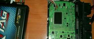
Dear drivers, one of the reasons for poor engine starting is a burnout in the ECU of the power key gb10nb37lz.
But for some reason, many car owners immediately think that their Crankshaft Position Sensor has failed, I once had this problem. But this was also due to the fact that the wire from the sensor lay on ground and when the engine heated up, the braid melted and a short circuit occurred. In my blog: www.drive2.ru/l/6251079/
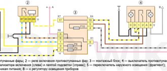
And so, our ignition diagram:
1 – battery 2 – ignition switch 3 – ignition relay 4 – spark plugs 5 – ignition module 6 – controller 7 – crankshaft position sensor 8 – master disk A – matching device
When the car does not start, most people immediately blame the crankshaft position sensor. Changing it they realize that it didn’t help. When checking the block, the wire does not give any result. The next steps are to install a new module, or this also does not give the computer anything. The car still won't start.
Everything is simple: the crankshaft sensor just has its own resistance, like the ignition module, by ringing it you can understand whether they are in good condition. Also don’t forget to check the fuse and main relay. Next, we check the spark plugs and armor wires to see if the retractor on the starter works (just put your hand on it, and if it doesn’t hit when starting, it means it’s working). During this check, you can understand what is wrong.
Checking the Crankshaft Position Sensor:
2. We quickly move the screwdriver blade close to the end of the sensor, while we observe voltage surges on the voltmeter.
Conclusion: The sensor is working.
Checking the DPKV circuit: With the ignition off, disconnect the engine management system wiring harness block from the crankshaft position sensor. We connect the tester probes to terminal “B” of the wiring harness block and engine ground.
Video “No spark and blown fuse - repairing the ECU”
What to do if there is no spark and the fuses are constantly blowing - the video below shows the process of repairing the control controller in a garage (the author of the video is the Auto Practice channel).
I came across an article by McSystem. Actually, here it is below
In January - about Januarys. Again and in detail about the ECM-ECU masses
So, on to the topic! Classic ECM 21124 with ECU January 7.2(+) or M7.9.7 Electrical connection diagram of ECM EURO-2 M7.9.7, January 7.2 LADA 2110 with engine 21124. 21124-1411020-30, 21124-1411020-31.32
Fig. 1 ECM 21124 January 7.2, M7.9.7 Noticed, often described and characteristic problems - unstable idle speed, freezing speed, “jerking” of the engine at start and operation of the cooling fan, unreasonable jumps in the electrical parameters of the ECM during diagnostics. And this is not the entire list. And the whole problem is a rather incorrect wiring of the harness masses, not in relation to the body, but to the ECU. Therefore, in this article you will not see recommendations for tightening the “hoses” of additional mass to the ECU, due to its complete uselessness. This is not a newfangled “razmasovka” or “razminusovka”... Don’t get your hopes up!
The main idea voiced by the authors is that the wiring of the power lines of the ECU and fan and low-current sensor masses is fundamentally incorrect. Rice. 12
Fig.2 Ground connections of the ECM. S6, S7, S8
The sensors must be connected to the ground bus of the ECU board and not have contact with the body! There should be no flow of pulsed and direct currents of the ECU and IM in the sensor mass circuit. And the ECU is securely connected to the body. The rationale is to eliminate the influence of ECU currents (pulse and constant) and fan current on the reliability of sensor readings. Classic approach with data collection and processing systems! But not from AvtoVAZ designers, as usual... Now, in order
Fig. 3 Masses according to AvtoVAZ, or how not to do it
What VAZs “think”: everything about the ECUs on the VAZ 2110-2112 and their replacement
The ECU is the main control module in any car. Thanks to the control unit, the optimal parameters for the operation of the power unit are determined, so this module must always work exactly like a clock. Where is the VAZ 2110 ECU located, what malfunctions are typical for it and how to change the device if necessary - we will talk about this below.
What should I change it to?
Please note that if your old controller fails, you should replace it with exactly the same one that was installed previously - that is, straight from the factory. The price of such devices, depending on the type and year of manufacture of your car, can be in a wide range and range from 4,500 to 10,000 rubles .
Hello everyone, I am the proud owner of a VAZ-2112 and I can tell you a lot of interesting things about it. In particular, the ECU is also an electronic control unit, on this car model, and in principle as on basically all VAZ models, it is located in a very inconvenient place, namely under the torpedo trim on the passenger side, in order to get to it, you need to take Phillips screwdriver and go ahead.
Hello. I seem to have figured out where the ECU is located, but my question is, can it be reinstalled in a more convenient place?
The electronic control unit on the VAZ-2112 is located under the torpedo trim on the passenger side. Then all that remains is to take a Phillips screwdriver and get to it.
The site is replete with advertising. It's not pleasant to be on the page.
Description of "brains"
The VAZ 2110 is considered the first vehicle in the domestic automobile industry equipped with an injection engine. The power unit is controlled by an ECU, an electronic device that determines the basic parameters of engine operation in accordance with sensor signals. In fact, the ECU of a VAZ 2110, VAZ 2112 or any other model is the “brains” of the car, the operation of which affects the functionality of the vehicle as a whole.
Control controller in VAZ 2110
In the “Tens”, as well as the VAZ 2112, there are 16 valves and other models equipped with BOSCH 7.9.7 or January 7.2 systems, one M6 screw is installed in the head. From this screw the mass is taken to the ignition coils, and the mass is taken directly to the control model in the cabin. Typically, the mass is a welded stud mounted on the ECM bracket, particularly behind the center console, behind the left screen. In this case, the mass is transferred to the bracket through a pin, which is welded on the engine shield in the middle. It should also be noted that the nut on this stud is not usually tightened.
Control unit location
Now let's consider the location of the VAZ 2110 ECU. This device in the Ten is located under the center console, in its lower part, in particular, under the control panel. In order to gain access to the control module, you must remove the plastic panel on the passenger side, to do this you will have to use a Phillips screwdriver. Once you remove the cover, you will see many different wires, plugs, and safety devices. The controller itself is located behind them, it is screwed to the bar in a horizontal position.
The arrow indicates the location of the ECM module behind the center console
Typical malfunctions: their symptoms and causes
If the electronic engine management system malfunctions, this can lead to problems with the operation of the power unit. Unfortunately, ECU malfunctions in dozens of domestic cars are not uncommon, so the car owner should be aware of the main problems, as well as the reasons for their occurrence.
First, let's look at the symptoms of malfunctions:
As for the reasons, malfunctions in the electronic control unit can occur as a result of:
Instructions for removing and replacing the computer
The need to dismantle the ECM unit 16 of the ten valve engine arises if repairs are necessary when faults are identified. The repair process itself will depend on what exactly happened in the operation of the ECU. For example, if the contacts on the module connector have oxidized, the unit must be dismantled to clean or replace them. If the reason lies in damage to the housing, then the device must be removed for replacement; if water has gotten inside, then the module should be removed in order to dry it. Only after you have dried the block can it be tested.
If the problem lies in the performance of the board and some burnt-out elements, then you can try to repair it yourself by re-soldering some components. But we would still recommend turning to specialists for help, especially if you have never encountered such a problem before (the author of the video about repairing the control controller is Vyacheslav Chistov).
Tools
To replace the module, you will need:
Work sequence
Before dismantling the device, you should disconnect the negative terminal from the car battery:
Do not attempt to repair the control unit if you have never had to deal with such a task before.!