You will find the answer to this question in the photo report on the modification of the backlight of the BSK Auto VAZ 2110.
In order for the BSK block to be illuminated, the drawing of the machine must be visible. Inserts in BSK modules are available with or without translucent patterns.
I made my insert when I was finalizing the BSK module, where I made the printed drawing of the car transparent.
The backlight was made from 5 mm plexiglass.
I cut out a rectangle 44x22 millimeters. (a little wider than the “car” drawing).
I took a small LED with a diameter of 3 millimeters. I drilled holes for it in the end of the plexiglass.
To install the plexiglass with the LED, I cut out a rectangle (in the part of the module that is located under the insert, in the “machine” area)
In order to prevent the backlight from getting onto the adjacent indicators, I covered the back and ends of the plexiglass with a film that does not transmit light.
The wires from the LED were connected to the module plug.
“Plus” (long leg of the LED) was connected through a resistance (1.5 kOhm, power 0.5 W) to pin “1”
"Minus" to contact "3".
The car lights turn on when the ignition is turned on.
On-board control system of the VAZ 2110 and its purpose
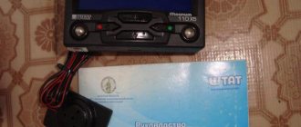
VAZ 2110 on-board system unit
The VAZ 2110 on-board control system is represented by several sensors and alarms that help eliminate deficiencies in the operation of the vehicle system. At one moment they may no longer be necessary, and at another they can save a person from unexpected breakdowns or even save a person’s life. Their serviceability must be constantly monitored. In order for the on-board display unit of the VAZ 2110 control system to always remain in working condition, you need to know the number of sensor data.
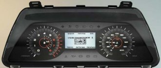
Indication symbols
As you know, all the lights on the control panel come on when the ignition is turned on, and then, when the engine is already running, most of them go out. But when one remains on or blinks, this cannot but be alarming, because not everyone can immediately figure out what malfunctions this indicates, which of the systems needs urgent repairs.
Let's look at the designations of the instrument panel of the VAZ 2110. You should know that regardless of whether the panel is new or old on your car, the designations are almost the same, but the indicators may be located slightly differently.
Before deciding to upgrade the instrument panel, it is recommended to understand its pinout. Details: https://vazweb.ru/desyatka/elektrooborudovanie/raspinovka-paneli-priborov.html
Top part
So let's start from left to right. First, the top part of the control panel:
- Side scale from 50 to 130 and arrow. Shows the temperature of antifreeze (antifreeze) in the engine cooling system;
- Almost round scale (0 – 80) and arrow. Tachometer showing engine speed;
- Two arrows at the top, almost in the middle of the control panel - turn signals (right, left);
- Speedometer. Well, this device, probably everyone knows, shows the speed at which the car is moving;
- A side scale with an arrow and, most often, two images of a filling column (white and red). Instead of a red column there may be a yellow light. This is an indicator of the fuel level in the tank. If the red column (yellow light) lights up, it means that there is very little fuel left in the tank - no more than 7 liters, urgent refueling is required.
Additional panel
The additional front panel of the new-style BSK control has indicators:
- An oil can is shown. If the light works, check the oil level;
- An icon lights up, which, with some imagination, can be “identified” as working wipers. This indicates that there is not enough windshield washer fluid in the tank;
- Conventional image of a thermometer over a container with liquid - high temperature of antifreeze;
- A crossed out light, which the arrow points to, is a sign that the brake light or parking lights are not working;
- If the light with the image of a wheel with brake pads lights up, it is quite possible that the pads are worn out and require replacement;
- The sign of a man with a seat belt indicates that the seat belt should be fastened.
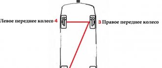
System problems
Summarizing the experience of drivers, the most common problems occur in the ignition switch. The limit switch in it should receive 12 volts. Sometimes it is the installers who confuse the diagram, after which the BSK not only does not see the door, but also does not work at all. To check functionality, you must disable the limit switch. If the BSK turns on, but does not see the door, then the problem is here.
For other cases, you will have to resort to checking the systems one by one according to the pinout diagram:
- Replacement and diagnostics of the coolant temperature sensor (DTOZH) VAZ 2114
- Checking and replacing the mass air flow sensor (MAF) on a VAZ 2114
- Outside air temperature sensor for VAZ 2114: purpose, causes of failure and ways to eliminate them
good afternoon, AM 2114 8 class. I encountered a problem, after starting the car the bsk started to light up just dimly (all diodes). Can anyone tell me what the problem is? Also, with each shutdown and start-up, the instantaneous mileage and clock began to reset to 00.
Nuances of work
However, these pinout diagrams for the VAZ 2110 are, so to speak, basic, mostly the same, but there are also differences in color markings (especially by manufacturer). Therefore, you need to either use the instruction manual that came specifically with your car, or, armed with a marker and self-adhesive labels, “write everything out” in detail and not get confused when installing a new instrument panel.
Connecting wires to the VDO panel on a VAZ 2110
Connecting wires to the “Schetmash” panel in Kursk on a VAZ 2110
Connecting wires to the “AP” panel in Vladimir on a VAZ 2110
Connecting wires to the panel from the Kalina car to the VAZ 2110
During subsequent assembly, there will probably be a lot of devices that are not taken into account here, and, taking into account modern realities, many car owners plan to install them on the updated dashboard.
All malfunctions of the ignition switch VAZ-2110
The ignition switch is a very important part that combines many functions. Its malfunctions on the “ten” are also varied and require a clear description.
The ignition switch on any car performs at least three functions: switching electrical circuits, access to starting the engine using a key, and locking the steering shaft for anti-theft purposes. On the “ten”, protection against restarting the starter, a forgotten key indication signal and illumination of the cylinder are added to this list.
Let's look at how it all works point by point and... breaks down!
The ignition switch contact group does not work
A contact group is a structure that closes various electrical contacts, depending on the position of the key in the lock. It is located in the back of the lock body and is capable of presenting unexpected surprises. If the contact group malfunctions, strange at first glance electrical problems arise in the car - for example, the headlights may fail, or the heater may stop working. A faulty contact group may also make it impossible to start the engine. In detail - in the article there are signs of a malfunction of the ignition switch contact group.
Reworking the low beam button
As already mentioned, the button for turning on the low beam and the button for the dimensions of the VAZ 2114 are combined and located in pairs. Their main drawback, which most car enthusiasts point out, is the absence of a power-on LED on the low-beam headlight button.
This problem is quite serious, since very often it becomes unclear whether the headlights are working or not (especially during daylight hours). You can solve this by upgrading the button yourself.
For this you will need:
- a button that will be redesigned;
- the second button is the same - donor;
- soldering iron or (better) soldering station.
The button modification should be carried out according to the diagram shown here. Resoldering the LED itself from one board to another is highly not recommended, since this requires a soldering station equipped with a hair dryer, a special flux and high skill in working with them.
First, we need to remove the main button from the car panel (how to do this has already been discussed above).
After it is removed and disconnected from the wires, perform the following operations:
- remove the keys by prying them off with a flat screwdriver;
- we disassemble the body of the buttons by pressing the latches with a screwdriver (the buttons themselves at this moment must be in the “on” position);
- we see that the sidebar button has two diodes (backlight and indication), and the low headlight button has only a backlight button;
- remove a pair of legs and a pair of contacts from the donor button;
- we rearrange them into the free spaces on the working button;
- remove the board from the donor button with two diodes and insert it into the working button instead of the board with one diode;
- solder the board to the legs that were added;
- make a hole in the button cover (this can be done with a sharp knife or simply punched with a flat screwdriver).
The junction of the newly installed legs and the new board must be well soldered. Otherwise, the button may quickly fail or not work correctly.
After all these operations have been completed, all that remains is to assemble everything in the reverse order and install the upgraded button in its place (during installation, it is important that all the mini-latches on the case fall into place)
Typical faults
The need for replacement, as a rule, arises in the event of malfunctions in the operation of the device. If the computer begins to show incorrect data, the cause of the problem may lie in the contacts. Usually the contacts come off as a result of off-road driving and frequent vibrations. In this case, the problem can be resolved by reconnecting the devices.
In some cases, incorrect data is caused by glitches. If this is the case, then you won’t be able to solve the problem on your own - only specialists with the necessary equipment can help. In practice, the bookmaker can be reflashed, that is, the software can be reinstalled. In the event that the demonstration of incorrect parameters is associated with damage to the electronics, then the only correct solution is to replace the BC. Usually in this case, if there is mechanical damage to the system elements, the on-board computer does not work, which is the reason for its replacement (the author of the video is the IZO)))LENTA channel).
Basic principles
Regardless of the type of engine used, the basis of the wiring used in the VAZ 2110 car is the same. It's easy to find a diagram, but not so easy to understand.
Let's look at the basic principles of wiring.
- All equipment and devices powered by electricity in the VAZ 2110 are based on a single-wire connection. VAZ designers specially provided for wires of certain colors to each be responsible for their own functions. Therefore, certain equipment is connected using wires of their own color. This allows you to independently understand the wiring, make it easier to carry out repair work and not spend money on car repair services.
- The downside to the VAZ 2110 is that the mass is the car body itself.
- The positive wire of the batteries on the top ten always comes only in red. Therefore, when making repairs, try not to change the color of the wire, so as not to confuse yourself.
- For each system that is connected to the electrical system, it is equipped with its own separate wiring harness.
- The VAZ 2110 is designed in such a way that when the battery is turned on, all electrics and electrical equipment are energized. This is related to the most common recommendation, which you have seen more than once in our materials, where we described the repair or replacement of certain components - disconnecting the negative terminal from the battery.
- Do not forget about the existence of the so-called contactless system. This system is required to create a high-quality spark, which is simply necessary to ensure combustion of the air-fuel mixture. In order for a contactless system to function, high voltages are indispensable.
Carburetor models
The first versions of the VAZ 2110 model, which the domestic plant began to produce, were equipped exclusively with carburetor engines. Only after some time more modern injection versions appeared. They are objectively better. But this does not take away the fact that many have dozens of them under the hood with a carburetor.
Are there any significant differences in terms of electrical circuitry between a carburetor and an injector? We can say no. The carburetor systems used are almost entirely the same as on the more modern version.
Part of interior wiring
Also, you will not encounter serious problems in the form of electrical wiring if you suddenly want to replace a carburetor engine with an injection engine or equip the car with additional electrical equipment. You will even find identical plugs in the engine compartment.
The only nuance of switching from a carurator to an injector is the need to install additional wiring from the fuel pump to the on-board computer.
Injector
In addition to the wiring, which is identical for the carburetor and injector, the latter is additionally equipped with fuses and sensors.
In practice, due to the large number of regulators that ensure the operation of an electronic engine control unit of an injection type with 8 or 16 valves (there is none on the carburetor), the system turns out to be more complex. To repair it, you need to carefully understand all the components and their location.
Electrical diagram
This option is for those who want to illuminate the BSK block without plexiglass
We erase the front plate with a stationery knife.
Print out the same drawing again, but on matte paper.
It goes something like this
Then I made holes in the case with a soldering iron.
To diffuse the light, I inserted pieces of transparent plastic into these holes (cut from a simple CD box) and made one side matte with a knife, but better with sandpaper
Now we are illuminating the Vase, which I forgot to photograph.
To illuminate the BSK module, I took a diode strip (2 pieces from it)
There are no pictures, so I took approximately the same module as a base and added LED strips there. I think the meaning is clear.
The strips need to be glued between the door LEDs
I soldered the backlight wires to pins 1(+) and 3(-) to these
Now the drawn car on the block will glow brightly when the ignition is on.
In order for the car to not glow so brightly, I soldered a 620 Ohm resistor to the positive wire.
Diagnostics using a scanner
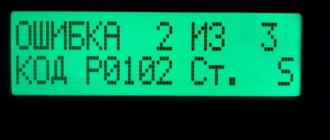
The method involves connecting an external computer with the program installed. This opens up more opportunities for car diagnostics. In this case, error codes for VAZ 2110 and VAZ 2112 consist of 5 characters.
- P – failure or malfunction of the power plant, transmission;
- B – body systems are damaged;
- C – a problem has been detected in the vehicle’s chassis;
- U – violation of pairing of different modules.
- 0 – general value;
- 1/2 – manufacturer code;
- 3 – reserve.
- 1-2 – violation in the air-fuel mixture supply devices;
- 3 – malfunction of the ignition units;
- 4 – atmospheric emissions control device;
- 5 – malfunction of the engine speed or engine speed meters;
- 6 – failures in electronics;
- 7-8 – malfunction of the gearbox module;
- 9-0 – reserve unit.
The last two digits give the serial number of the breakdown and its location.
Correct operation
With the right approach, the installed BC will not cause problems.
However, if it shows unreliable information, then it is worth removing the on-board computer and checking it for serviceability. How to remove the device is clear. After all, it has a disconnectable connector, so you need to dismantle it in the reverse order. The main thing to remember is that this is a fragile thing and can be broken. After dismantling, you should check the integrity of the soldering and wires and eliminate any breaks . Afterwards, put the device where it was before and use the working device again.
vote
Article rating
How to install a voltmeter on a VAZ 2114
Damn, I didn’t think of building it into this crap, I installed it in a plug that covers the place of the on-board computer. I took the minus from the body, the plus from the ignition switch. you did everything more sophisticatedly and painlessly. The only remark is that you didn’t secure the voltmeter inside the case, I would have added some hot glue) Like for sure!
I did everything clearly, only the voltmeter needs to be connected directly from the battery or generator. To give accurate readings. And so you show 0.5-0.7 volts less.
Is Patamushta a name or a nickname?
It seems to me alone that there is something sparkling in the nutria near the brains, if you reconsider at 4.30 minutes.
Why do many people refer to screws as bolts?
Is it impossible to install an on-board computer instead of a plug without a collective farm?
Although I have it in my dashboard, both in the standard BC and in the non-standard BC, but why is it needed? If there is something wrong with the generator, then the battery icon will appear on the dashboard, but before the winter cold I still charge it.
For what