As the requirements for the engine power supply system became more stringent, carburetors, as the most complex components on the way of gasoline and air to the cylinders, underwent serious modifications and went from simple fuel sprayers to serious multi-tasking pneumohydraulic devices.
In Russia, this path ended with the creation of Solex-type carburetors; nothing more advanced was produced in our country; the time has come for fuel injection systems.
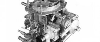
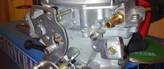
Carburetor
Carburetor appearance
1 – throttle valve zone heating unit; 2 – engine crankcase ventilation fitting; 3 – accelerator pump cover; 4 – electromagnetic shut-off valve; 5 – carburetor cover; 6 – air filter mounting pin; 7 – air damper control lever; 8 – starter cover; 9 – sector of the throttle valve drive lever;
10 – wire block of the EPHH screw sensor; 11 – adjusting screw for the “amount” of idle mixture; 12 – economizer cover; 13 – carburetor body; 14 – fuel supply fitting; 15 – fuel outlet fitting; 16 – adjusting screw for idle mixture composition (arrow); 17 – fitting for supplying vacuum to the vacuum ignition regulator.
Diagram of the design and operation of the carburetor
I – first chamber; II – second chamber; 1 – accelerator pump drive lever; 2 – adjusting screw; 3 – starting device diaphragm; 4 – air channel of the starting device; 5 – electromagnetic shut-off valve; 6 – idle fuel jet; 7 – main air jet of the first chamber; 8 – idle air jet; 9 – air damper; 10 – sprayer of the main dosing system of the first chamber; 11 – accelerator pump nozzles; 12 – sprayer of the main dosing system of the second chamber; 13 – econostat sprayer; 14 – main air jet of the second chamber; 15 – air jet of the transition system of the second chamber; 16 – channel for balancing the float chamber; 17 – float chamber; 18 – needle valve; 19 – calibrated hole for fuel bypass into the tank; 20 – carburetor fuel filter; 21 – fuel supply fitting; 22 – power mode economizer diaphragm; 23 – fuel jet of the power mode economizer; 24 – ball valve of the power mode economizer; 25 – float; 26 – econostat fuel jet with tube; 27 – fuel nozzle of the transition system of the second chamber with a tube; 28 – emulsion tube of the second chamber; 29 – main fuel jet of the second chamber; 30 – outlet openings of the transition system of the second chamber; 31, 33 – throttle valves; 32 – slit of the transition system of the first chamber; 34 – outlet of the idle system; 35 – throttle valve zone heating unit; 36 – adjusting screw for the composition (the “quality” screw) of the idle mixture; 37 – engine crankcase ventilation fitting; 38 – fitting for supplying vacuum to the vacuum ignition regulator; 39 – main fuel jet of the first chamber; 40 – emulsion tube of the first chamber; 41 – ball valve of the accelerator pump; 42 – accelerator pump diaphragm.
A carburetor is used to prepare the fuel-air mixture of the required composition (depending on the engine mode). On engines -2108, -21081 and -21083, Solex-type carburetors are installed - emulsion type, two-chamber, with sequential opening of the throttle valves. The throttle valve drive is mechanical, cable. Carburetors have a balanced float chamber, a crankcase exhaust system, heating of the throttle valve area of the first chamber, a manual starting device, and an electromagnetic idle shut-off valve. The -21081 engine is equipped with a 21081-1107010 carburetor, the -2108 engine is equipped with a 2108-1107010 carburetor, and the -21083 engine is equipped with a 21083-1107010 carburetor. These carburetors are structurally similar and differ only in the flow sections of the jets.
Fuel is supplied to the carburetor through a strainer and needle valve. The latter maintains a given fuel level in the float chamber.
The float chamber is two-sectional (this design reduces the influence of fuel level fluctuations on engine operation when the vehicle turns and rolls). From the float chamber, fuel flows through the main fuel jets (first and second chambers) into the emulsion wells, where it is mixed with air passing through calibrated holes in the upper part of the emulsion tubes (main air jets). Through the nozzles, the fuel-air emulsion enters the small and large diffusers of the carburetor.
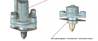
The idle system takes fuel from the emulsion well, after the main fuel jet of the first chamber. The fuel passes through the idle air jet (structurally combined with an electromagnetic idle shut-off valve), after which it is mixed with air from the channel from the idle air jet and from the expanding part of the diffuser (for stable operation when switching to idle mode). The resulting emulsion is fed under the throttle valve through a hole closed by a “quality” screw. The “quantity” screw (number of revolutions) adjusts the opening value of the throttle valve of the first chamber at idle.
When the throttle valve of the first chamber is partially opened (before the main metering system is turned on), the air-fuel mixture enters the chamber through a vertical slot located at the level of the throttle valve in the closed position; when the throttle valve of the second chamber is partially opened - through a hole located just above the throttle valve (second chamber) in the closed position.
The power mode economizer comes into operation when the throttle valves are opened significantly. Fuel is drawn from the float chamber through a ball valve. As long as the economizer diaphragm is held by vacuum in the intake manifold, the valve is closed. When the throttle valves open, the vacuum behind them drops and the valve begins to pass fuel, which flows through the economizer jet into the emulsion well, bypassing the main jet, enriching the mixture.
The econostat provides additional fuel supply directly from the float chamber (through the econostat nozzle and a tube system) into the second chamber. The econostat switches on at maximum power modes, further enriching the working mixture.
The accelerator pump is a diaphragm type, mechanically driven from the throttle valve axis of the first chamber through a profile cam. When the throttle valve opens, the cam acts on the lever, which in turn acts on the diaphragm. A portion of fuel is injected through nozzles into the carburetor chambers, enriching the combustible mixture during acceleration modes. The pump is equipped with two ball valves: a check valve is located in the channel connecting the float chamber with the cavity of the accelerator pump; it opens when it is filled with fuel (the gas pedal is released and the return spring moves the diaphragm back), and closes when fuel is pumped. The other valve is located in the sprayer; it opens under the pressure of the pumped fuel and closes under its own weight as soon as the fuel supply stops. This prevents fuel from leaking out of the channels and air leaks. The pump performance is not adjustable and depends only on the cam profile.
The starting device serves to enrich the air-fuel mixture when starting a cold engine. It is controlled from the driver’s seat with a “choke” handle via a rod. When the handle is pulled all the way, the three-arm air damper control lever, turning on an axis, acts with a profile groove on the air damper lever, closing it. In this case, with its outer profile (in the lower part) it acts on the throttle valve control lever of the first chamber, opening it slightly to the starting gap C (its value is adjusted by a screw on the lever). After the engine starts, the vacuum in the intake manifold increases; it is transferred to the cavity of the trigger device. Under the influence of vacuum, the diaphragm of the starting device, overcoming the resistance of the return spring, through the rod slightly opens the air damper to the starting gap B (its value is adjusted by a screw on the cover of the starting device). When the air damper control handle is recessed, gaps C and B are reduced; their value with a partially recessed handle depends on the profiles of the three-arm lever (its cutout and outer profile) and cannot be adjusted. If the choke control handle is pulled out, then when you press the gas pedal, only the throttle valve of the first chamber will open, while the throttle valve of the second chamber is blocked by the choke control lever. This prevents jerks and dips when driving with a cold engine (“on choke”).
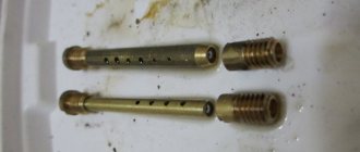
Correct selection and replacement of the injection pump bypass valve
Reducing valves have an extremely simple design, but they are constantly subjected to high loads and quite often fail. Valve malfunction is manifested by deterioration of engine performance - it loses throttle response and in some modes there is a noticeable deterioration in its performance. In these cases, it is necessary to dismantle and check the valve, and, if it is faulty, replace it.
To replace, it is necessary to select a bypass valve of the same type and model that is installed on the injection pump by the manufacturer - only in this case there is a guarantee that the valve has the necessary characteristics and will ensure normal operation of the pump. Many valves allow adjustment of the pressure at which fuel is bypassed - this adjustment must be made in strict accordance with the instructions for maintenance and repair of the car/tractor. As a rule, adjustment comes down to changing the number of washers placed under the valve head, although there are exceptions - it all depends on the specific type of device.
With the correct selection, replacement and adjustment of the pressure reducing valve, the fuel pump will operate effectively in all modes, ensuring normal operating characteristics of the power unit.
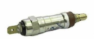
The fuel line and the injector ramp that supplies the engine injectors operate under a pressure of about 3 bar. Since gasoline is supplied by an electric pump, the system uses a special valve that limits the fuel pressure. Otherwise, the nozzles will leak and the engine will choke on the over-enriched mixture. To avoid problems with fuel supply, you need to promptly diagnose the signs of a malfunction of the fuel pressure regulator (abbreviated as RTD) and know how to eliminate it.
Carburetor calibration data
| Options | 2108-1107010 | 21081-1107010 | 21083-1107010 | |||
| First camera | Second camera | First camera | Second camera | First camera | Second camera | |
| Mixing chamber diameter, mm | 32 | 32 | 32 | 32 | 32 | 32 |
| Diffuser diameter, mm | 21 | 23 | 21 | 23 | 21 | 23 |
| Main dosing system: | ||||||
| fuel jet marking | 97,5 | 97,5 | 95 | 97,5 | 95 | 97,5 |
| air jet marking | 165 | 125 | 165 | 135 | 155 | 125 |
| Emulsion tube type | 23 | ZC | 23 | ZC | 23 | ZC |
| Idle system and transition system | ||||||
| first chamber: fuel jet marking | 42* | — | 40* | — | 40* | — |
| air jet marking | 170 | — | 170 | — | 170 | — |
| Second chamber transition system: | ||||||
| fuel jet marking | — | 50 | — | 50 | — | 50 |
| air jet marking | — | 120 | — | 120 | — | 120 |
| Econostat: | ||||||
| conditional fuel jet flow rate | — | 60 | — | 70 | — | 70 |
| Power mode economizer: | ||||||
| fuel jet marking | 40 | — | 40 | — | 40 | — |
| spring compression force at a length of 9.5 mm, N | 1,5±10 % | — | 1,5±10 % | — | 1,5±10 % | — |
| Accelerator pump: | ||||||
| sprayer marking | 35 | 40 | 35 | 40 | 35 | 40 |
| fuel supply for 10 cycles (total for both chambers), cm3 | 11,5 | 11,5 | 11,5 | |||
| cam marking | 7 | — | 4 | — | 7 | — |
| Starting clearances: | ||||||
| air damper (gap B), mm | 3±0,2 | — | 2,7±0,2 | — | 2,5±0,2 | — |
| throttle valve (gap C), mm | 0,85 | — | 1,0 | — | 1,1 | — |
| Hole diameter for vacuum corrector, mm | 1,2 | — | 1,2 | — | 1,2 | — |
| Needle valve hole diameter, mm | 1,8 | 1,8 | 1,8 | |||
| Diameter of the fuel bypass hole into the tank, mm | 0,70 | 0,70 | 0,70 | |||
| Engine crankcase ventilation hole diameter, mm | 1,5 | — | 1,5 | — | 1,5 | — |
* Selected at the factory when setting up the carburetor.
What brands and models of cars were installed on?
C were installed not only on VAZs. Other automakers also actively used them for their cars.
Table: modifications and applicability of Solex carburetors
| Modification | Applicability | Engine volume, cm3 | Notes |
| DAAZ-2108–1107010 | VAZ 2108, 2109 | 1,3 | |
| DAAZ-21081–1107010 | VAZ 21081, 21091, ZAZ 1102 | 1,1 | |
| DAAZ-21083–1107010 | VAZ 21083, 21093, 21099 | 1,5 | |
| DAAZ-21083–1107010–31 | VAZ 2108, 2109, 2110, 2111 | 1,5 | Has a semi-automatic starting device |
| DAAZ-21083–1107010–35 | VAZ 2108, 2109, 2110, 2111 | 1,5 | Has a two-level semi-automatic starting device (winter/summer) |
| DAAZ-21083–1107010–62 | VAZ 2109, 2115 | 1,5 | Has an electronic device for controlling the composition of the combustible mixture |
| DAAZ-21083–1107010–05 | VAZ 2109 | 1,5 | |
| DAAZ-21412–1107010, DAAZ-21412–1107010–30 | AZLK 2141, 2141–23 | 1,5/1,8 | |
| DAAZ-1111–1107010 | VAZ 1111, 11113 "Oka" | 0,65/0,75 | |
| DAAZ-21051–1107010 | VAZ 2103, 2105 | 1,5 | |
| DAAZ-21053–1107010 | VAZ 21074, 21061 | 1,6 | |
| DAAZ-21051–1107010–30 | VAZ 2104, 2105 | 1,3 | |
| DAAZ-21053–1107010–62 | VAZ 2107, 21072, 21074 | 1,3/1,5/1,6 | |
| DAAZ-21073–1107010 | VAZ 2121, 21213 "Niva" | 1,6/1,7 |
Setting up the float chamber
This type of work allows you to adjust the optimal amount of gasoline in the float chamber. An incorrect level causes a decrease in power, uneven engine operation, and excessive fuel consumption.
- set of wrenches;
- thin probe (diameter 1 mm);
- pliers.
1. Remove the air filter and unscrew the carburetor cover.
2. Carefully remove the float chamber cover.
3. Check the condition and position of the floats. They should be parallel to the imprints of the side walls of the float bath on the gasket.
4. If they are displaced, we align them by bringing them together or spreading them apart.
5. Next, lay the lid horizontally with the floats up and use a feeler gauge to measure the distance from the bottom of the float to the gasket. It should be equal to 1 mm. If it is higher or lower, we continue further adjustment after installing the carburetor on the engine.
6. When fuel is pumped into the float chamber, its level should coincide with the red lines, as shown in the photo.
7. If the floats are set incorrectly, this level will be lower or higher. Simple adjustment is carried out by bending or bending the tongue of the floats, then closing the carburetor cover and pumping fuel.
For details on setting up the float chamber, see here
Why is a control valve needed?
The fuel supply system of most passenger cars requires continuous operation of an electric fuel pump. It constantly pumps gasoline into the fuel line and ramp, raising the pressure to the maximum (5–7 Bar depending on the brand of car). But such performance is needed only under increased load on the engine, when it develops high speeds and consumes a lot of fuel mixture. In normal mode, a fuel pressure at the injectors of 3–3.5 bar is sufficient.
The fuel pressure diaphragm valve, installed in the engine power system after the fuel pump, performs 3 main functions:
- Limits the fuel pressure in the line at low engine loads, dumping excess fuel back into the tank through a separate tube.
- When the gasoline consumption of the power unit increases, the return flow is partially or completely blocked by the regulator. In this way, the valve maintains the minimum pressure required for normal operation of the motor.
- Maintaining pressure for a long time after stopping the power unit.
Without an RTD, the pump would “push through” the locking mechanisms of the injectors and gasoline would flow into the cylinders uncontrollably. In addition, the regulator protects the line from leaks at the connections, which will inevitably appear under the influence of strong pressure.
Setting up the launcher
- open-end wrench 7;
- open-end wrench 8;
- flat screwdriver;
- electronic tachometer or multimeter with its function.
1. Remove the air filter from the carburetor. Pull the “suction” towards you as far as it will go. Next, you will need an assistant to start the engine. At this time, you are watching the starter flap, which should open slightly after starting.
2. If this does not happen, it means that the starter is not adjusted.
3. We begin the adjustment. Warm up the engine, turn it off and connect the tachometer as follows.
4. Pull out the choke and start the engine. The suction valve must be completely closed.
5. Next, use a screwdriver to press on the edge of the damper, opening it 30 0 .
8. In this position, holding the bolt with a screwdriver, tighten the locknut.
The adjustment process can be seen in this video
Idle setting
- flat screwdriver;
- electronic tachometer.
1. Start the engine, warm it up to operating temperature, and then turn it off. We press the “choke” all the way, opening the flap of the starter device as much as possible. We connect the tachometer using the same principle.
2. Start the engine, turn on all the lights and the heater fan at full power.
4. If in this way it was not possible to achieve the required speed, unscrew the quality screw to the maximum number of revolutions. Next, turn the quantity screw, setting the motor to 900 rpm. After this, use the quality screw to reduce the speed to 800 rpm.
Details in the video
How to reduce fuel consumption on a Solex
If you notice that the engine begins to consume more fuel than it should, do not be lazy to check it. The rated fuel consumption for any vehicle can be found in its operating manual. It should be borne in mind that the amount of fuel consumed can be influenced by many factors, from the quality of the gasoline itself to the tire pressure, so before checking, take the trouble to diagnose the ignition system and also adjust the valves.
Flow check
Required tools:
- clean empty plastic bottle (2 l);
- a piece of gas-resistant hose (50–80 cm) with a clamp of the appropriate diameter;
- gasoline (1–2 l);
- marker;
- crosshead screwdriver.
Check procedure:
- We are looking for a flat section of the road (3 km) with good surface and low traffic intensity.
- Warm up the engine to operating temperature and turn it off.
- Using a screwdriver, loosen the clamp screw on the suction fitting of the fuel pump.
- We put one end of the prepared piece of hose onto the fitting. We fix the connection with a clamp.
- We pour a certain amount of gasoline into the bottle, measuring it out into 50 or 100 ml portions and making the appropriate marks on the bottle with a marker. We will use them to determine consumption.
- We lower the other end of the hose from the gas pump into the bottle.
- We start the engine and move along the road section at a speed of 60–70 km/h in fourth gear.
- After driving 3 km, we stop, look at the bottle, estimate the consumption and compare it with the passport data.
Design and operating principle
The carburetor supplies the engine with a fuel-air mixture in various modes. When starting from a “cold” state, the throttle valve is manually fully opened (the so-called “choke”), and the mixture entering the cylinders is completely enriched. After the engine warms up, the speed drops and the choke can be removed. Drivers remove it in different ways, but it is recommended to do it gradually.
The fuel in the carburetor is transferred to the float chambers from the diaphragm pump, and the needle valve controls the gasoline level. Through the chamber, the fuel passes into the channels of the body, where it enters the nozzles, and through them it goes into the first chamber. A fuel-air mixture is formed, which is supplied directly to the cylinders by the gas pedal. The second camera turns on only during sharp acceleration and operation at high speeds.
At idle, the IACV (idle speed solenoid valve) is turned on, while the engine runs stably and the car consumes much less fuel. However, on some devices it can be disabled; if it breaks down, the speed and consumption will only increase slightly, but the car will drive.
How does Solex differ from Ozone and Weber?
The main difference between Solex carburetors and devices of previous families is the possibility of installing it on transversely located power units with the float chamber forward. This installation option made it possible to eliminate the leanness of the fuel mixture when the car enters a turn, climbs, or during sudden acceleration.
In addition, Solex has a completely different float chamber design. It has a two-section design, which allows the device to be used both on front-wheel drive cars and on classic cars.
Solex carburetors are reliable and maintainable
Signs of a carburetor malfunction
It is a well-known fact: the quality of fuel in our country leaves much to be desired. As a result, the carburetor may become clogged with oils, solid particles, etc.
In this case, one or more signs may be observed:
- significantly increased fuel consumption;
- the engine does not start “cold”;
- loss of dynamics;
- "triple" of the engine.
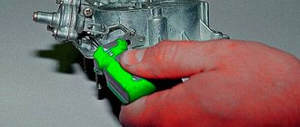
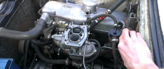
You can restore functionality yourself. If unsuccessful, you can remove it and take it to a mechanic, who, with an experienced eye, will immediately identify the errors and adjust it “by eye,” after which the car will at least start.
First, you can try adjusting the carburetor without removing it from the car.
What is a fuel injection pump bypass valve
The injection pump bypass valve (reducing valve) is a high-pressure fuel pump assembly of diesel engine power supply systems, an adjustable valve (hydraulic throttle) for draining excess fuel and maintaining the required fuel pressure in the pump.
The bypass valve performs several functions:
- Draining excess fuel from the pump;
- Removing air trapped in the fuel system;
- Maintaining constant fuel pressure inside the pump (in the channels of the pump sections of multi-section high-pressure fuel pumps and in the housing of the distribution high-pressure fuel pumps).
Setup and adjustment
First of all, the engine warms up until the fan turns on. Next, adjust the speed by ear using the quantity screws. The operation should be smooth, with a sharp press on the gas pedal there should be no dips, and the speed should increase quickly and smoothly. The quality screw regulates the amount of exhaust gases. Ideally, no escaping gases should be visible from the exhaust pipe in the dry season (they will be, but not visible to the eye, if everything works correctly). Everything can also be done by looking at the tachometer readings. Unfortunately, many models of Soviet cars do not have it at all, so most often the adjustment will have to be done by ear.
Possible problems when setting up XX
When the quantity screw is tightened, the engine does not react at all . This problem can occur when a large amount of fuel enters the idle diffuser. There may be several reasons for this:
- an XX jet of a larger size than necessary is installed;
- the plug or solenoid valve is not tightened properly, so gasoline is sucked in, bypassing the XX jet;
- The jet or its seat is deformed.
To identify the specific cause of the above problem, it is necessary to disconnect the wire from the valve while the engine is running, and the motor should immediately turn off. If this happens, most likely the wrong size XX jet is installed. When the engine does not stall when the power supply to the valve is turned off, it means that fuel is supplied bypassing the exhaust system, including the nozzle itself.
To eliminate the malfunction, first remove the plug or solenoid valve and check the condition of the nozzle and seat for any deformations. If the seat is damaged, you will have to replace the carburetor cover. If no damage or deformation is detected, put the jet on the solenoid valve and lubricate the o-ring with oil. Then we tighten the nozzle with a wrench, holding it with one finger without much effort.
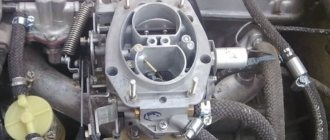
Lada 2106. › Logbook › Solex carburetor 083 (Pekar) a lot of literature. And Photos of works.
The figure shows a VAZ Solex 21083 carburetor.
The design of the carburetor VAZ Solex 21083.
1. Carburetor heating unit 2. Throttle valve of the first chamber 3. Pipe for suction of crankcase gases 4. Accelerator pump drive lever 5. Accelerator pump drive cam 6. Accelerator pump diaphragm 7. Power mode economizer fuel nozzle 8. Pump housing 9. Economizer diaphragm power modes 10. Shut-off solenoid valve 11. Idle fuel jet 12. Carburetor cover 13. Main air jet of the first chamber 14. Air damper 15. Accelerator pump nozzles with fuel supply valve 16. Starter diaphragm 17. Starter adjustment screw 18. Adjusting screw for the amount of idle mixture 19. Locking lever of the second chamber 20. Pipe for supplying vacuum to the vacuum regulator of the ignition distributor 21. Adjusting screw for the quality of the idle mixture 22. Throttle valve control sector 23. Throttle valve drive lever 24. Adjusting screw for opening the throttle damper of the first chamber 25. Air damper control lever 26. Starter rod 27. Electrical wire of the limit switch of the forced idle economizer 28. Air damper lever 29. Main air jet of the second chamber 30. Emulsion tube 31. Sprayer of the main dosing system of the second chamber 32. Fuel supply pipe 33. Fuel drain pipe into the tank 34. Fuel filter 35. Needle valve 36. Second chamber throttle valve 37. Second chamber throttle lever 38. Second chamber main fuel jet 39. Second chamber throttle drive lever 40. Float
Solex 21083 carburetor design
1 – driving lever, second drive chamber; 2 – screw adjusting the amount of mixture supplied for idle speed; 3 – sector for heating the carburetor; 4 – engine crankcase ventilation pipe; 5 – drive lever for the accelerator pump; 6 – solenoid shut-off valve; 7 – air damper lever; 8 – carburetor cover; 9 – special screw for fastening the liquid chamber; 10 – liquid chamber body; 11 – carburetor body; 12 – throttle valve lever of the second chamber; 13 – control lever block directly for the throttle valves; A - special marks for precise installation of the bimetallic spring of the starting device.
1 – axis for the float; 2 – needle valve; 3 – float; 4 – special gasket for the carburetor cover; 5 – starter cover; 6 – screw; 7 – trigger device diaphragm; 8 – special gasket; 9 – air damper lever; 10 – idle fuel jet; 11 – solenoid shut-off valve; 12 – pipe for supplying a combustible mixture; 13 – carburetor cover; 14 – fuel filter; 15 – housing assembly with drive levers of a semi-automatic starting device; 16 – screws for adjusting the air damper of the starting gap and slightly opening the first throttle chamber; 17 – special clamp for securing the bimetallic spring housing; 18 – liquid chamber; 19 – assembled housing with a bimetallic spring; 20 – bimetallic spring screen.
Solex 21083 carburetor diagram
1 – screw adjusting the amount of feed mixture for idle speed; 2 – electric wire of the limit switch economizer for forced idling; 3 – carburetor heating unit; 4 – diaphragm for the accelerator pump; 5 – accelerator pump cover; 6 – drive lever of the accelerator pump; 7 – accelerator pump drive cam; 8 – economizer cover for power modes; 9 – diaphragm for economizer of power modes; 10 – fuel jet for power mode economizer; 11 – power mode economizer valve; 12 – nozzles with a fuel mixture supply valve for the accelerator pump; 13 – sprayers of the main dosing systems; 14 – air main jets with emulsion tubes; 15 – fuel main jets; 16 – carburetor body; 17 – adjusting screw for the throttle valve; 18 – stopper for the adjusting screw; 19 – stopper cap; 20 – throttle valve of the second chamber; 21 – throttle valve axis of the second chamber; 22 – throttle valve rod for opening the first chamber; 23 – block with throttle valve control lever; 24 – return spring of the throttle valve of the first chamber; 25 – driven lever, drive of the throttle valve of the second chamber; 26 – driving lever, driving the throttle valve of the second chamber; 27 – spring of the throttle valve drive levers of the second chamber; 28 – throttle valve of the first chamber; 29 – return spring of the throttle valve of the second chamber; 30 – plug for the screw adjusting (composition) the quality of the idle mixture; 31 – axis of the throttle valve of the first chamber; 32 – screw adjusting the quality of the supplied idle mixture
Problems with the accelerator pump
The accelerator pump serves to consistently and timely supply a fuel stream through an uncovered carburetor valve. A weak flow or dripping is not considered normal. Spreading fuel along the walls of the diffuser is also taken as a deviation.
The acceleration pump nozzles are inserted into different chamber compartments. However, for speed, they can only be installed in the primary, which in exceptional cases will result in excessive overflow.
What is a Solex 21083 carburetor?
Solex 21083 is one of the most popular domestic carburetors. It is mainly installed on 1.5-liter Russian and Soviet-made engines, although they can often be seen, for example, on old carburetor Japanese cars, since they are much simpler in design than their analogues. This carburetor will work normally only with a contactless ignition system, due to a number of technical features. There are many options for the Solex carburetor, however, 21083 is the basic option. It is this type that is most popular, as it can be easily modified by installing different jets, or even boring diffusers. It is not recommended to install Solex 21083 on cars with a displacement of more than 1.5 liters. The car, of course, will drive, but the failure in dynamics will be obvious; installing jets with greater cross-country ability will no longer help.
Let's sum it up
The steps described above for setting up and adjusting a Solex carburetor are basic. In other words, if you wish, you can adjust the carburetor yourself, based on this information. Note that the accuracy of the settings can be further checked on a gas analyzer, after which you can make the necessary adjustments yourself instead of constantly contacting specialists. Finally, we add that a dosing device of this type lends itself to various types of tuning, all kinds of modifications and improvements. For this reason, when choosing a carburetor for a VAZ, it is not for nothing that many car enthusiasts prefer Solex.
Design and operating principle
The carburetor supplies the engine with a fuel-air mixture in various modes. When starting from a “cold” state, the throttle valve is manually fully opened (the so-called “choke”), and the mixture entering the cylinders is completely enriched. After the engine warms up, the speed drops and the choke can be removed. Drivers remove it in different ways, but it is recommended to do it gradually.
The fuel in the carburetor is transferred to the float chambers from the diaphragm pump, and the needle valve controls the gasoline level. Through the chamber, the fuel passes into the channels of the body, where it enters the nozzles, and through them it goes into the first chamber. A fuel-air mixture is formed, which is supplied directly to the cylinders by the gas pedal. The second camera turns on only during sharp acceleration and operation at high speeds.
At idle, the IACV (idle speed solenoid valve) is turned on, while the engine runs stably and the car consumes much less fuel. However, on some devices it can be disabled; if it breaks down, the speed and consumption will only increase slightly, but the car will drive.
What troubles can happen with the second camera?
The secondary chamber system cannot be regulated due to the original jets produced at the factory, as well as the econostat located in its planes, since it is this that supplies additional fuel to enrich the mixture when a vacuum forms in the carburetor caused by high speeds.
The acceleration pump nozzle is perhaps the only element that can undergo slight changes in cases where the flow of gasoline does not reach its intended place.
Signs of a carburetor malfunction
It is a well-known fact: the quality of fuel in our country leaves much to be desired. As a result, the carburetor may become clogged with oils, solid particles, etc.
In this case, one or more signs may be observed:
- significantly increased fuel consumption;
- the engine does not start “cold”;
- loss of dynamics;
- "triple" of the engine.
You can restore functionality yourself. If unsuccessful, you can remove it and take it to a mechanic, who, with an experienced eye, will immediately identify the errors and adjust it “by eye,” after which the car will at least start.
First, you can try adjusting the carburetor without removing it from the car.