Modern cars can have several types of engines: gasoline or diesel. And they, in turn, differ in the amount of torque, power, volume and crankshaft speed. In addition to the engines in a car, the gearbox may also differ, which in turn can be of four types:
- robot;
- machine;
- Mechanics;
- variable speed drive.
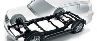
And in order to adapt the gearbox to a certain type of engine and vehicle, the final drive plays an important role. It has a certain gear ratio.
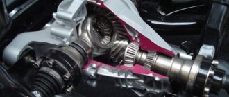
The final drive of a car is a gear or chain type transmission mechanism for a passenger car, as well as all self-propelled vehicles. This mechanism is designed to transmit torque directly to the drive wheels.
Main gear with differential: 1 - axle shafts; 2 — driven gear; 3 - drive gear; 4 — axle gears; 5 — satellite gears.
Where is the final drive?
The main task of the gear reducer is to increase engine torque and reduce the speed of rotation of the drive wheels. If the car is front-wheel drive, then this mechanism is located in the gearbox directly next to the differential.
If the car has rear drive wheels, then the drive axle housing serves as the location of the transmission. This is also where the differential is located. In the case of an all-wheel drive vehicle, the final drive is located depending on the type of drive. In any case, it will be located either in the gearbox or in the drive axle housing.
Classification
The final drive may differ depending on the number of gear stages. This is how they distinguish: 1. Single gear, consisting of driven and driving gears. 2. Double gear has two pairs of gears. This type is most often found in trucks, because they require an increased gear ratio.
In turn, the double main gear of the car can be central and separate. The first type is located in the axle housing of the driving pair of wheels, and the transmission of the second type is divided. One part of the gear stage is located in the hub of the driving pair of wheels, and the second is in the driving axle.
The main gear may also differ in the type of gear connection: 1 - cylindrical; 2 - hypoid; 3 - worm; 4 - canonical.
Cylindrical type transmission
It is found in front-wheel drive cars, in which the engine and gearbox are located in a transverse position. In this case, gears with chevron and oblique teeth are used. The gear ratio of such a transmission ranges from 3.5 to 4.2. If this value increases, there will be a corresponding increase in the noise level and frequency, as well as dimensions.
Modern cars with a manual transmission may contain not one output shaft, but two or three. In this case, each such shaft will have its own drive gear. In turn, all gears will be meshed with one driven one. The robotic DSG gearbox has the same final drive design.
On vehicles with front-wheel drive, the main gear can be replaced. This change is a tuning of the transmission, which allows you to increase the acceleration dynamics of the car and at the same time reduce the load that is transferred to the gearbox and clutch.
Transmission of rear wheel drive cars
All other types of final drives are found in rear-wheel drive vehicles. Indeed, in this situation, the engine and gearbox are parallel to the movement and therefore torque is transmitted to the drive axle perpendicularly.
If we talk about the final drive of rear-wheel drive cars, the most popular is the hypoid gear. It has the lowest load on the tooth and also provides less noise. When operating a hypoid gear, efficiency decreases, since the existing displacement in the meshing of gears increases sliding friction.
For a passenger car with a hypoid gear, the gear ratio is 3.5-4.5, and for trucks - from 5 to 7. This gear differs from a cylindrical gear in that the shaft axis does not intersect with the gear, since with this design it is possible to lower the cardan transmission and reduce the position of the body, which will lead to greater stability of the car itself.
We recommend: Pros and cons of diesel engine chip tuning
If the dimensions and noise level are not important, then in this case the main gear of the canonical type is used. Worm gears are practically never found, since their production requires large financial and labor costs.
Video:
Lubrication is necessary for the operation of any rubbing parts and gear teeth. Therefore, depending on the location of the main gear, oil is poured into the crankcase of the block or rear axle. And its level is important to control in order to ensure proper operation of the relevant car parts.
( 2 times, rating: 5.00 out of 5)
Loading…
Who's in charge here and why?
So, the main transmission of a car is a unit, without which the efforts of the engine and gearbox would be a waste of energy. Why? The fact is that it is she who is responsible for transmitting torque from the gearbox directly to the drive wheels.
In addition, rotation, as a rule, still needs to change direction - from longitudinal (along the axis of the car) to transverse in order to get to the wheels. And all this is performed, in fact, by one gear mechanism, also known as a gear reducer. In addition to everything, the gear ratios are selected in such a way as to increase the torque of the motor.
Gear ratios (row)
Gear ratios are the gears in each gear, which also have their own size.
Gear ratios characterize the speed characteristics of a car in a particular gear. On a standard VAZ the following numbers are used:
| Gearbox ratios: | |
| I | 3636 |
| To me | 1,95 |
| Third | 1357 |
| IV | 0,941 |
| IN | 0,784 |
| counter | 3,53 |
The above characteristics are shown only with standard gear ratios.
The standard row on the VAZ 2114 is far from ideal: the first gear is a bit short, the second is long. Because of this, there is a sharp drop in dynamics when switching from first to second gear. Not only is there a malfunction, but also when switching sharply, the second gear synchronizer slowly dies.
Therefore, there are sports series where the gap between 1 and 2 is eliminated, and not only: the sports series are selected depending on the type of engine: it can be just a good city engine, or a sports one, or a prisoner for 402 meter races. There are also “turbo” transmissions designed for a turbo engine.
main gear
The main gear serves to increase the overall gear ratio and transmit torque through the differential (or turning mechanism) and final drives to the drive wheels of the tractor (car).
Based on the number of pairs of gears, single and double main gears are distinguished, and by design - bevel with spiral teeth, hypoid and cylindrical.
The main transmission of the tractor is a single gear consisting of a pair of bevel or spur gears. The final drives of a car can be single or double. Single gears are bevel gears with hypoid gearing, which reduces noise during gear operation and reduces the overall dimensions and weight of the drive axle. They are used on light and medium-duty passenger cars.
Drawing. Types of main gears of tractors and cars: a - bevel with spur gearing; b - conical with helical gearing; c - conical with hypoid gearing.
Double final drives consist of a pair of bevel gears and a pair of spur gears. Bevel gears are made with a spiral tooth, and cylindrical gears are made with straight, oblique or chevron teeth.
Replacing wheelsets
Often standard wheels are not enough to overcome serious off-road conditions. When installing special rubber, the main pair is usually replaced. The characteristics of standard wheelsets are designed specifically for the use of factory tires. If you don't replace the wheelsets when switching to larger wheels, they won't last long.
When installing military bridges, the main thing is to be aware of why you need a car. If it was purchased exclusively for off-road use, then a military bridge is the best solution. For a car that will have to be used frequently on the highway, this is not the best choice.
Design and basic requirements for the main gear
The design of the mechanism in question is simple: the main gear consists of two gears (gear reducer). The drive gear is smaller in size, and it is connected to the output shaft of the gearbox. The driven gear is larger than the drive gear, and it is connected to the differential and, accordingly, to the wheels of the car.
Scheme of the main gear of the driving axle of the car: 1 - drive wheels; 2 - axle shaft; 3 - driven gear; 4 - drive shaft; 5-drive gear
Let's consider the basic requirements for the main gear:
- minimum level of noise and vibration during operation;
- minimum fuel consumption;
- high efficiency;
- ensuring high traction and dynamic characteristics;
- manufacturability;
- minimum overall dimensions (to increase ground clearance and not raise the floor level in the car);
- minimum weight;
- high reliability;
- minimal need for maintenance.
The efficiency of the main gear can be increased by increasing the quality of manufacturing of the teeth of both gears, as well as by increasing the rigidity of the parts and using rolling bearings in the design. Note that it is most often necessary to reduce vibration and noise during operation for gear reducers of passenger cars. Vibrations and noise can be minimized by ensuring reliable lubrication of the teeth, increasing the accuracy of gear engagement, increasing the diameter of the shafts, and other measures that increase the rigidity of the mechanism elements.
Principle of operation
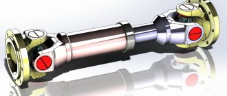
General view of a hypoid final drive
The principle of operation of the final drive is quite simple: while the car is moving, torque from the engine is transmitted to the variable gearbox (Gearbox), and then, through the main gear and differential, to the drive shafts of the car. Thus, the final drive directly changes the torque that is transmitted to the wheels of the machine. Accordingly, through it the speed of rotation of the wheels also changes.
The main characteristic of this gearbox is the gear ratio. This parameter reflects the ratio of the number of teeth of the driven gear (connected to the wheels) to the drive gear (connected to the secondary shaft of the gearbox). The higher the gear ratio, the faster the car accelerates (more torque), but the maximum speed decreases. Reducing the gear ratio increases the maximum speed, while the car begins to accelerate more slowly. For each car model, the gear ratio is selected taking into account the characteristics of the engine, gearbox, wheel size, brake system, etc.
Types of car transmissions
The type of transmission system depends on the energy source and the method of transmitting torque from the internal combustion engine to the wheels of the vehicle. Automakers produce vehicles with several types of transmissions:
- mechanical;
- hydromechanical;
- electrical;
- hybrid.
Mechanical
The most common type of power transmission, present in all cars with a manual gearbox and clutch unit. The rotation of the crankshaft is transmitted through the clutch discs to the gearbox and other transmission units.
Hydromechanical
It is gaining popularity due to the widespread use of automatic transmissions in new car models. Mechanical rotation is transformed into fluid (oil) movement in the torque converter, a more advanced clutch replacement. The transmission of torque through the transformer is smoother.
We recommend: Gearbox starts singing: troubleshooting
Electric
Used in electric cars and cars with hybrid power plants. In the first case, electricity from the battery powers an electric motor that rotates the wheels. Autohybrids are equipped with two types of power plants: internal combustion engines, electric motors, and batteries. Some car models use an internal combustion engine only after accelerating to a certain speed; up to this point, the wheels are turned by electric current. Some solutions allow you to constantly move with the help of electric motors, using a low-power gasoline engine only to recharge the batteries.
Purpose, design features
The main task of this element is to change the torque before applying it to the wheel drive. The gearbox does the same, but it has the ability to change gear ratios by engaging certain gears. Despite the presence of a gearbox in the design of the car, the torque output from it is small, and the rotation speed of the output shaft is high. If you transfer rotation directly to the drive wheels, the resulting load will “crush” the engine. In general, the car simply will not budge.
The final drive of the car provides increased torque and reduced rotation speed. But unlike a gearbox, its gear ratio is fixed.
This transmission on a passenger car is a conventional single-stage constant mesh gearbox, consisting of two gears of different diameters. The drive gear is small in size and is connected to the gearbox output shaft, that is, rotation is supplied to it. The driven gear is much larger in size and it supplies the resulting rotation to the drive shafts of the wheels.
The gear ratio is the ratio of the number of gear teeth in the gearbox. For passenger cars this parameter is in the range of 3.5-4.5, and for trucks it reaches 5-7.
The higher the gear ratio (the greater the number of teeth on the driven gear relative to the drive gear), the higher the torque supplied to the wheels. In this case, the tractive effort will be greater, but the maximum speed will be lower.
The main gear ratio is selected based on the performance indicators of the power plant, as well as other transmission components.
The final drive design directly depends on the design features of the car itself. This gearbox can be either a separate unit installed in its own housing (rear-wheel drive models) or be part of the gearbox design (cars with front-wheel drive).
As for some all-wheel drive cars, they may use a different layout. If in such a car the location of the power plant is transverse, then the main gear of the front axle is included in the design of the gearbox, and the rear axle is located in a separate housing. In a car with a longitudinal layout, the main gears on both axles are separated from the gearbox and transfer case.
In models with a separate main gear, this gearbox performs one more task - it changes the angle of rotation by 90 degrees. That is, the gearbox output shaft and wheel drive shafts are perpendicular.
In front-wheel drive models, where the main gear is included in the gearbox design, these shafts are parallel, since there is no need to change the direction angle.
A number of trucks use two-stage gearboxes. It is noteworthy that their design can be different, but the most widespread is the so-called spaced layout, which uses one central gearbox and two wheeled (on-board) gearboxes. This design allows you to significantly increase the torque and, accordingly, the traction force on the wheels.
Drive cars
The peculiarity of the gearbox is that it evenly divides the rotation between both drive shafts. For straight-line motion, this condition is normal. But when cornering, the wheels of the same axle travel different distances, so it is necessary to change the rotation speed of each of them. This is the job of the differential used in the transmission design (it is installed on the driven gear). As a result, the main gear supplies rotation to the drive shafts not directly, but through the differential.
Primary requirements. Modern tendencies
The main gears are subject to many requirements, the main ones being:
- Reliability;
- Minimal maintenance required;
- High efficiency indicators;
- Smooth and silent;
- Minimum possible overall dimensions.
Naturally, there is no ideal option, so designers have to look for compromises when choosing the type of final drive.
It is not yet possible to abandon the use of final drives in transmission designs, so all developments are aimed at increasing performance indicators.
It is noteworthy that changing the operating parameters of the gearbox is one of the main types of transmission tuning. By installing gears with a changed gear ratio, you can significantly influence the dynamics of the car, maximum speed, fuel consumption, load on the gearbox and power unit.
Finally, it is worth mentioning the design features of dual-clutch robotic gearboxes, which also affects the final drive design. In such gearboxes, paired and unpaired gears are separated, so there are two secondary shafts at the output. And each of them transmits rotation to its own drive gear of the main gear. That is, in such gearboxes there are two driving gears, and only one driven gear.
DSG gearbox diagram
This design feature allows you to make the gear ratio on the gearbox variable. To do this, only drive gears with different numbers of teeth are used. For example, when using a number of unpaired gears, to increase traction, a gear is used that provides a larger gear ratio, and the gear of a paired row has a lower value of this parameter.
Excerpt characterizing the Front Axle
- Here, brother, we have such a mess for the second day. The regimental adjutant came in and confirmed the news brought by Zherkov. We were ordered to perform tomorrow. - Let's go, gentlemen! - Well, thank God, we stayed too long. Kutuzov retreated to Vienna, destroying behind him bridges on the rivers Inn (in Braunau) and Traun (in Linz). On October 23, Russian troops crossed the Enns River. Russian convoys, artillery and columns of troops in the middle of the day stretched through the city of Enns, on this side and on the other side of the bridge. The day was warm, autumn and rainy. The vast perspective that opened up from the elevation where the Russian batteries stood protecting the bridge was suddenly covered with a muslin curtain of slanting rain, then suddenly expanded, and in the light of the sun objects as if covered with varnish became visible far away and clearly. A town could be seen underfoot with its white houses and red roofs, a cathedral and a bridge, on both sides of which masses of Russian troops poured, crowding. At the bend of the Danube one could see ships, an island, and a castle with a park, surrounded by the waters of the Ensa confluence with the Danube; one could see the left rocky bank of the Danube covered with pine forests with the mysterious distance of green peaks and blue gorges. The towers of the monastery were visible, protruding from behind a pine forest that seemed untouched; far ahead on the mountain, on the other side of Ens, enemy patrols could be seen. Between the guns, at a height, the chief of the rearguard, a general, and a retinue officer stood in front, examining the terrain through a telescope. Somewhat behind, Nesvitsky, sent from the commander-in-chief to the rearguard, sat on the trunk of a gun. The Cossack accompanying Nesvitsky handed over a handbag and a flask, and Nesvitsky treated the officers to pies and real doppelkümel. The officers joyfully surrounded him, some on their knees, some sitting cross-legged on the wet grass. - Yes, this Austrian prince was not a fool to build a castle here. Nice place. Why don't you eat, gentlemen? - said Nesvitsky. “I humbly thank you, prince,” answered one of the officers, enjoying talking with such an important staff official. - Beautiful place. We walked past the park itself, saw two deer, and what a wonderful house! “Look, prince,” said the other, who really wanted to take another pie, but was ashamed, and who therefore pretended that he was looking around the area, “look, our infantry have already climbed there.” Over there, in the meadow outside the village, three people are dragging something. “They will break through this palace,” he said with visible approval. “Both,” said Nesvitsky. “No, but what I would like,” he added, chewing the pie in his beautiful, moist mouth, “is to climb up there.”
GP on rear wheel drive cars
Other types of final drives are installed on rear-wheel drive cars, since the engine and gearbox are parallel to the drive, and torque is supplied to the drive axle vertically.
Rear-wheel drive cars most often have a hypoid gear, which has the least load on the tooth and creates a minimum degree of noise. During operation, the efficiency decreases, since the displaced fastenings of the gear wheels increase the coefficient of friction during sliding.
On cars with a hypoid gearbox, the gear ratio is 3.5 - 5.4, on trucks 5 - 7. This gear differs from a cylindrical gear: the shaft axis does not intersect with the gear, because the shape allows the cardan to be lowered and the body clearance to be reduced, this leads to maximum vehicle stability.
If the car owner is not interested in the size and degree of noise, then a canonical type GP is used. Worm gears are installed very rarely, since their production is labor-intensive and expensive.
For normal functioning of rubbing elements and teeth, lubrication is required. Special oil is poured into the crankcase or rear axle. Its level must be monitored to ensure stable operation of machine elements.
Required care
Any gears of the main gear and self-block need lubrication and maintenance. Despite the fact that all elements of the GP and self-block look like powerful pieces of hardware, they still have their own durability resource. Because of this, advice regarding sudden starts and braking, rough clutch engagement and other vehicle loads remain relevant today.
All rubbing elements and gear teeth must be lubricated regularly. Because of this, special oil is poured into the crankcase, the level of which must be checked occasionally.
The oil in which the gears operate can leak through weak connections and worn-out seals.
If there is any doubt about the occurrence of any malfunction in the transmission, it is necessary to raise the drive wheel of the machine using a jack. Start the motor and gear to rotate the wheel. Look at all the rotating parts, listen for any strange or suspicious noise.
Then you should jack up the other wheel. If there is significant noise, vibration or oil droplets, you must contact a car service center.
Where is?
We seem to have figured out the purpose of the car’s main gear; now it would be nice to find it. Doing this can be a difficult task, because the location of this unit can be different and depends on the type of machine drive and the imagination of the development engineers.
Fortunately, the flight of thoughts here is limited by the number of axes. So, for example, if we have front-wheel drive, then in this case the main gear of the car should be looked for in the gearbox along with the differential, in vehicles with rear drive wheels - directly in the rear axle. If all four are leading, then choose one of the above options.
Classification of final drives
By the number of pairs of gears
- Single - has only one pair of gears: driven and driven.
- Double - has two pairs of gears. Divided into double central or double spaced. The double central one is located only in the drive axle, and the double spaced one is also located in the hub of the drive wheels. It is used in trucks, as they require a higher gear ratio.
Single and double final drive
We recommend: Fuel pump for VAZ 2110
By type of gear connection
- Cylindrical. Used on front-wheel drive vehicles in which the engine and gearbox are transversely located. This type of connection uses gears with herringbone and helical teeth.
- Conical. Used on those rear-wheel drive cars in which the size of the mechanisms is not important and there are no restrictions on the noise level.
- Hypoid is the most popular type of gear connection for rear-wheel drive vehicles.
- Worm gear is practically not used in the design of car transmissions.
Cylindrical final drive
By layout
- Placed in the gearbox or power unit. On front-wheel drive vehicles, the main gear is located directly in the gearbox housing.
- Placed separately from the checkpoint. In rear-wheel drive vehicles, the main pair of gears is located in the drive axle housing along with the differential.
Note that in all-wheel drive vehicles, the location of the main pair of gears depends on the type of drive.
Bevel final drive
How does the service work?
Gearbox maintenance is rarely done; usually everything is limited to changing the oil. At a mileage of over 150,000 km, the bearing may need to be adjusted, as well as the contact patch between the driven and drive gears. When changing the oil, it is extremely important to clean the cavity from wear products (small chips), as well as dirt. It is not necessary to use flushes for the axle gearbox; it is enough to use 2 liters of diesel fuel and let the unit run at low speeds.
Tips on how to extend the performance of the GP and differential:
- change the oil in a timely manner, and if your driving style is more sporty, the car endures high loads (driving at high speed, transporting cargo);
- When changing the oil manufacturer or changing the viscosity, flush the gearbox;
- When driving over 200,000 km, it is recommended to use additives. Why is an additive needed? Molybdenum disulfide, contained in the additive, reduces friction of parts, as a result of which the temperature decreases, the oil retains its properties longer. Remember that if the main pair is heavily worn, there is no point in using an additive;
- Avoid starting with slipping.
The most common signs of transmission failure
The most difficult transmission element to repair is the gearbox. The car owner should be wary of:
- difficulties when changing gears, crunching, creaking, other extraneous sounds when moving the lever to another position;
- it is impossible to engage the gear;
- a strong smell of engine oil appears in the cabin;
- rustling, knocking noises when the gear shift lever is in neutral.
An oil leak from the gearbox is a serious reason to immediately contact a specialist. Lack of lubrication can completely damage the mechanism.
Damage to the cable or a “weak” clutch pedal can lead to “sticking” of the clutch. When you press the pedal, the discs will not be able to separate, and you will not be able to change the speed. At the same time, an unpleasant grinding sound is heard.
Double final drives
These transfers apply
on medium- and heavy-duty trucks, on all-wheel drive three-axle vehicles and buses to increase the transmission ratio to ensure the transmission of high torque. The efficiency of double final drives is within
0,93…0,96
.
Double final drives have two gear pairs
and usually consist of a pair of bevel gears with spiral teeth and a pair of spur gears with straight or oblique teeth. The presence of a cylindrical pair of gears allows not only to increase the gear ratio of the main gear, but also to increase the strength and durability of the bevel gear pair.
In the central main gear
(Figure 2, d) bevel and cylindrical pairs of gears are located in one housing in the center of the drive axle. The torque from the bevel pair is supplied through the differential to the driving wheels of the car.
In a spaced main gear
(Figure 2, e) the bevel gear pair 5 is located in the housing in the center of the drive axle, and the cylindrical gears 6 are in the wheel gearboxes. In this case, the cylindrical gears are connected by axle shafts 7 through a differential with a bevel pair of gears. The torque from the bevel pair through the differential and axle shafts 7 is supplied to the wheel gearboxes.
Widely used in spaced final drives
received
single-row planetary wheel gearboxes
.
Such a gearbox consists of spur gears - sun gear
8,
crown gear
11 and three
satellites
9. The sun gear is driven into rotation through the axle shaft 7 and is meshed with three satellites, freely mounted on axles 10, rigidly connected to the bridge beam. The satellites mesh with a ring gear 11 attached to the wheel hub. The torque from the central bevel gear pair 5 to the hubs of the drive wheels is transmitted through the axle differential 7, sun gears 8, satellites 9 and ring gears 11.
When splitting the final drive
the load on the axle shafts and differential parts is reduced by two parts, and the dimensions of the crankcase and the middle part of the drive axle are also reduced. As a result, ground clearance increases and thereby improves the vehicle's cross-country ability. However, the spaced main gear is more complex, has a higher metal consumption, is expensive and labor-intensive to maintain.
Differential
The differential is a planetary mechanism designed to distribute torque between the drive axles of a tractor or car and ensure that the drive wheels rotate at different frequencies when driving on a curved or uneven road. When turning, on an uneven road, the drive wheels move in arcs of different lengths. If both wheels were located on a common axis, their movement would be accompanied by slipping, tire wear and breakdown. Therefore, the drive wheels are mounted on separate axles - axle shafts connected by a differential.
Let's consider the principle of operation of the differential according to the diagram presented in Figure a. Gears: satellite 7 (Figure a) is connected to racks 6 and 8 (in the actual design these are gears 6 and 8). A force P is applied to shaft 10 of gear 7, tending to move this gear upward.
If the resistance of racks 6 and 8 to movement by force P is the same, then equal forces P/2 act on their teeth and the racks, together with gear 7, move upward. However, if the resistance to the movement of one of the racks, for example, rack 6, is greater than rack 8, gear 7 will begin to rotate around its axis and, rolling along rack 6, will move rack 8 up even faster. In this case, the speed of rack 8 increases as much as the speed of rack 6 decreases to 2 times the speed of shaft 10.
He drew. Diagram of the differential and its locking mechanism: a - diagram of the differential; b - differential circuit with a blocking mechanism; 1 - body; 2 — cam on the differential housing; 3 — differential lock mechanism fork; 4 - movable cam clutch; 5, 9 — axle shafts; 6, 8 — axle gears; 7 — satellite; 10 — satellite axis; 11 — driven bevel gear of the main gear.
Now let's look at a real differential circuit (Figure b). In the bosses of the housing 1, a satellite gear 7 is freely installed on the shaft 10. The holes in the side bosses of the housing serve as a support for the axle shafts 5 and 9 with bevel axle shafts 6 and 8 mounted on them coupled with the satellite gear 7. Rotation to the differential housing 1 is transmitted from the main gear 11 driven gear. If shafts 9 and 5 have the same resistance to rotation, then satellite 7, jammed by gears 6 and 8, is stationary on shaft 10 and the entire system rotates as a single unit.
If the resistance to rotation of one axle shaft, for example, axle shaft 9, is greater than the resistance of axle shaft 5, then the satellite 7, rotating around its axis, will slow down the rotation of gear 8 and accelerate the rotation of gear 6, as happened in the example with the movement of gear 7 and racks 6 and 8 ( see figure a).
Changing the rotation speed of the axle shafts by the differential when the resistance in the wheels fluctuates reduces the tractor's maneuverability on wet or loose soil. In difficult ground conditions, it is better to disable the differential to improve wheel traction. For this purpose, tractors are equipped with differential locking mechanisms, which are very diverse in design.
Differential locking mechanisms
Differential locking mechanisms are divided into:
- forced
- auto
- self-locking
And by disk type up to:
- mechanic
- hydraulic
Forced (mechanical) blocking of the differential occurs when the movable cam clutch 4 (see Fig. b), installed on the splines of the tractor half-shaft 5, engages with cams 2 on the differential housing 1. In this case, the rotation speeds of the differential housing 7 and the axle shaft 5 will be the same, i.e. the differential will be locked.
The locking mechanism is activated by a pedal (or handle) and released by a retractable spring when the force applied by the driver stops.
Automatic differential lock allows the driver to make no effort: the process of turning the mechanism on and off occurs automatically. Automatic differential locking is used on tractors MTZ-80, MTZ-82, T-150K, etc.