Electric sema VAZ 21102
A
— blocks for connecting the rear window washer motor.
B
- blocks for connecting the injection system harness.
C
- to the warning light harness block.
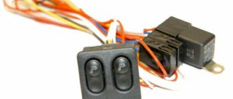
D
— block for connection to the on-board computer.
E
- to the headlight cleaner harness block.
F
— block for connection to the fuel level sensor in the electric fuel pump module.
G
- to the rear window heating element.
H
- block for connecting an additional brake signal.
J
- to the trunk lock motor.
The diagram does not conventionally show that in the instrument panel wiring harness, the second ends of all wires of white, black, orange, white with a red stripe and yellow with a blue stripe are connected to each other at the same points.
Connection diagram of the engine management system 2111 with distributed fuel injection of the VAZ-21102 car
- 1 – injectors 2 – spark plugs 3 – ignition module 4 – diagnostic block 5 – controller (since 2000, a modification of the system with M1.5.4N or “January-5.1” controllers has been produced) 6 – cooling system fan electric motor 7 – block attached to instrument panel wiring harness 8 – main relay 9 – fuse connected to the main relay 10 – electric fan relay 11 – fuse connected to the electric fan relay 12 – electric fuel pump relay 13 – fuse connected to the electric fuel pump relay 14 – mass air flow sensor
- 15 – throttle position sensor
- 16 – coolant temperature sensor
- 17 – CO potentiometer (not installed on vehicles with a modified control system, CO adjustment is carried out using the DST-2 device through the diagnostic block)
- 18 – idle speed regulator
- 19 – knock sensor
- 20 – crankshaft position sensor
- 21 – vehicle speed sensor
- 22 – immobilizer control unit
- 23 – immobilizer status indicator
- 24 – electric fuel pump with fuel level sensor
- 25 – oil pressure warning lamp sensor
- 26 – coolant temperature indicator sensor
- 27 – oil level sensor
- 28 – knock sensor (installed on vehicles with a modified control system)
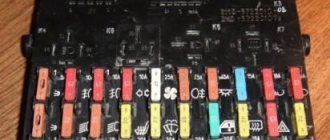
Fuse box VAZ-2110, VAZ-2111, VAZ-2112
F1 - 5A - License plate lamps. Instrument lighting lamps. Side light indicator lamp. Trunk light. Left side marker lamps. F2 - 7.5A - Left headlight (low beam). F3 - 10A - Left headlight (high beam). F4 - 10A - Right fog lamp. F5 - 30A - Electric door window motors. F6 - 15A - Portable lamp. F7 - 20A - Electric motor of the engine cooling system fan. Sound signal. F8 - 20A - Rear window heating element. Relay (contacts) for turning on the heated rear window. F9 - 20A - Recirculation valve. Windshield and headlight cleaners and washers. Relay (coil) for turning on the heated rear window. F10 - 20A - Reserve. F11 - 5A - Starboard side marker lamps. F12 - 7.5A - Right headlight (low beam). F13 - 10A - Right headlight (high beam). Indicator lamp for turning on the high beam. F14 - 10A - Left fog lamp. F15 - 20A - Electric seat heating. Locking the trunk lock. F16 - 10A - Relay-breaker for direction indicators and hazard warning lights (in emergency mode). Hazard warning lamp. F17 - 7.5A - Interior lighting lamp. Individual backlight lamp. Ignition switch illumination lamp. Brake light bulbs. Clock (trip computer). F18 - 25A - Glove box lighting lamp. Heater controller. Cigarette lighter. F19 - 10A - Door locking. Relay for monitoring the health of brake light lamps and side lights. Direction indicators with warning lamps. Reversing lamps. Generator excitation winding. On-board control system display unit. Instrument cluster. Clock (or trip computer). F20 - 7.5A - Rear fog lamps.
There are no fuses in the starting circuit.
Relay designation:
K1 – relay for monitoring the health of light bulbs; K2 – front wiper relay; K3 – repeater and alarm relay; K4 – low beam relay; K5 – high beam relay; K6 – additional relay; K7 – relay for turning on the heated rear window; K8 – backup relay (not installed on 110 series vehicles);
How to preserve a VAZ-2111 in winter
In order for the VAZ-2111 to serve for a long time, it is necessary not only to promptly eliminate faults related to the operation of the electrical circuit, but also to properly maintain the car. Experts give the following recommendations:
- Washing is good, but after cleaning the car it won’t be superfluous to treat the body parts with liquid wax. Why is this necessary? Wax fills even the smallest pores that appear in the paint, and dirt does not penetrate there, which means you can save money on another wash.
- If you are not satisfied with the roughness that a rag leaves after wiping off dirt, use polishing and rub the liquid glass. The latter will keep the VAZ-2111 in the best condition for at least 1.5 years.
- Many owners of domestic cars want to turn a boring vehicle into a real modern car. To do this, owners stick stickers on the surface, but no one takes into account that they are a real dust collector for small debris and dirt.
- Drive your car with care - service station workers assure that any scratch can be retouched by painting the part, but they do not specify that it is almost impossible to select an identical shade of paint previously used by the manufacturer. Therefore, the entire car has to be repainted.
- The headlights of the VAZ-2111 are made of plastic - this is how the designers take care of the recycling of raw materials. But plastic wears out over time and becomes cloudy. To extend the life of your headlights, initially protect the surface with armored film.
- There is an opinion that seat covers prevent abrasion of the seats themselves, but this is not the case. Moreover, it is easy to wash the seats; special products are used for this.
Replace your wipers promptly; they will protect the glass from scratches.
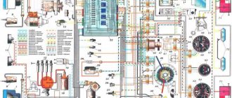
This free collection contains all the necessary documentation for the electrical equipment of the VAZ-2111 car - the circuit itself, the heating system, headlight cleaner, electronic engine control module and fuse box. The VAZ 2111 is the first station wagon in the line of front-wheel drive cars, which is a modernized concept of the rear-wheel drive VAZ 2104. In it, the wiring diagram for the injector and a number of other components have undergone changes as part of the concept change. Diagrams for other models can be viewed here.
VAZ-2110 wiring diagram
Wiring diagram and troubleshooting
Electrical wiring plays one of the important roles in a car. The correct operation of the main devices and systems, as well as the vehicle as a whole, depends on it. Today we will look at the electrical wiring diagrams of the VAZ-2110 family.
Electrical wiring for the VAZ-2110 is of two types: carburetor and injector . There are slight differences, but the basic principles of operation and wiring are the same. Depending on the location, the wiring differs into: under the hood and in the cabin . All electrical equipment of the car is connected using wires of a certain color. Each element has its own wiring harness through the blocks and fuses.
The on-board voltage is 12V constant, minus on the car body.
Having a wiring diagram and knowing the operating principles of the main components of the car is not at all difficult to find the malfunction and the cause of its occurrence.
Before starting to repair the vehicle's electrical wiring (if this is not related to troubleshooting), the terminals should be removed from the battery.
Electrical diagram of a carburetor ignition system
At the first releases of the VAZ-2110, a carburetor was installed, which was later replaced by an injector, as a more modern and reliable system that ensures economical stable operation of the engine. The wiring of an engine with a carburetor includes almost the same vehicle life support systems as with an injector.
A
— the order of conventional numbering of plugs in the blocks of the mounting block, instrument cluster, ignition switch and gear motor of the windshield wiper
B
— the order of conventional numbering of plugs in the blocks of the ignition sensor-distributor and speed sensor
Notes:
1.
In the instrument panel wiring harness, the second ends of the white, black, orange, white with red stripe and yellow with blue stripe wires are connected to each other at the same points.
2.
The bends of the wires at the points of entry into the harness indicate the direction of their laying in the harness.
Electrical diagram of a contactless car ignition system
The carburetor is already an obsolete car part. It is less reliable and cannot provide such an accurate supply of the fuel mixture. In later releases, the carburetor ignition system was replaced with an injection system. The controller in this system “reads” the operation of all systems, thereby determining and setting many indicators - calculation of the fuel mixture, etc.
To find a wiring fault, you need to start looking in the contacts. Moreover, you need to check all the wires that are included in the harness: their visual integrity, resistance, reliability of contacts, etc. The underhood wiring has identical plugs.
In addition to the wiring that is provided for the VAZ 2110 - carburetor, "ten" - injector, it is also equipped with a number of fuses that protect almost all of it from the possibility of short circuiting. The fuse and relay box in VAZ-2110 cars is located in the car interior near the driver's seat, to the left and below the steering wheel.
Fuse box VAZ-2110, VAZ-2111, VAZ-2112
VAZ-2110 fuses (number, rating and what they are responsible for)
Structurally, fuses are not provided only for the supply of current by the wire from the battery, in the car starting and ignition circuit, as well as for the wire going to the generator.
To replace a faulty fuse, first find the one that has blown and be sure to eliminate the cause. After that, install a new one of the same value.
Do not replace fuses with jumpers; this may cause blocks and devices to become unusable, as well as a wiring fire!
F1 - 5A - License plate lamps. Instrument lighting lamps. Side light indicator lamp. Trunk light. Left side marker lamps. F2 - 7.5A - Left headlight (low beam). F3 - 10A - Left headlight (high beam). F4 - 10A - Right fog lamp. F5 - 30A - Electric door window motors. F6 - 15A - Portable lamp. F7 - 20A - Electric motor of the engine cooling system fan. Sound signal. F8 - 20A - Rear window heating element. Relay (contacts) for turning on the heated rear window. F9 - 20A - Recirculation valve. Windshield and headlight cleaners and washers. Relay (coil) for turning on the heated rear window. F10 - 20A - Reserve. F11 - 5A - Starboard side marker lamps. F12 - 7.5A - Right headlight (low beam). F13 - 10A - Right headlight (high beam). Indicator lamp for turning on the high beam. F14 - 10A - Left fog lamp. F15 - 20A - Electric seat heating. Locking the trunk lock. F16 - 10A - Relay-breaker for direction indicators and hazard warning lights (in emergency mode). Hazard warning lamp. F17 - 7.5A - Interior lighting lamp. Individual backlight lamp. Ignition switch illumination lamp. Brake light bulbs. Clock (trip computer). F18 - 25A - Glove box lighting lamp. Heater controller. Cigarette lighter. F19 - 10A - Door locking. Relay for monitoring the health of brake light lamps and side lights. Direction indicators with warning lamps. Reversing lamps. Generator excitation winding. On-board control system display unit. Instrument cluster. Clock (or trip computer). F20 - 7.5A - Rear fog lamps.
Fuse box relay (number and what includes)
K1 – relay for monitoring the health of light bulbs; K2 – front wiper relay; K3 – repeater and alarm relay; K4 – low beam relay; K5 – high beam relay; K6 – additional relay; K7 – relay for turning on the heated rear window; K8 – backup relay (not installed on 110 series vehicles);
troubleshooting
The search for any wiring fault always starts with the contacts.
To check the condition of the contacts, it is necessary to carefully inspect the wires included in the system harness. This is done using different methods. Namely:
- Visual integrity check;
- Checking resistance with a device;
- Inspection of reliability, contact integrity, etc.
Pay special attention to high-voltage wires. They have a great responsibility to ensure the performance of all volatile equipment. But at the same time they are in a rather unfavorable environment. This is why a common cause of device failure is a wiring problem.
There are several main signs of a malfunction in high-voltage wires:
- When the radio is operating, noises are heard that were not there before;
- When driving, the car periodically jerks;
- Fuel consumption indicators increase;
- The engine begins to choke at low speeds;
- Exhaust toxicity increases significantly.
Prevention measures
If you notice or suspect that there are some problems with the electrical wiring, use a multimeter to check the high-voltage resistance. This is done as follows:
- The black wire is inserted into the left hole;
- The red wire is installed in the middle;
- The multimeter turns on to the blue twenty position;
- The probes are closed to each other;
- If the multimeter shows that the resistance is zero, then everything is fine with the high voltages;
- If the arrow points to 1, then the resistance is higher than normal. This indicates that the damaged wire must be replaced.
Useful multimeter
Golden rules
There are two basic rules associated with checking and replacing high-voltage wires of the electrical circuit of your VAZ 2110. Be sure to rely on them.
- Different wires may show different resistance. This is due to the difference in length. Therefore, take into account the tips from the instruction manual, which indicates the normal resistance values of a particular high-voltage device.
- There is always an aggressive environment under the hood, which can lead to failure of one of the high-voltage circuits. But if one wire produces increased resistance, everything still needs to be changed. Because over time, the others will also fail if one of them is already damaged.
Before attempting to change or repair the wiring yourself, be sure to disconnect the negative terminal from the battery. An incredibly important rule that should never be forgotten.
VAZ 2110 diagram
1. block headlight; 2. front brake pad wear sensors; 3. fan motor activation sensor; 4. electric motor of the engine cooling system fan; 5. sound signal; 6. generator VAZ-2110; 7. oil level sensor; 8. carburetor solenoid valve control unit; 9. heater controller; 10. recirculation valve switch; 11. illumination lamp for heater control levers; 12. switch; 13. carburetor limit switch; 14. oil pressure warning lamp sensor; 15. spark plugs; 16. carburetor solenoid valve; 17. coolant temperature indicator sensor; 18. ignition distributor sensor; 19. ignition coil; 20. starter; 21. heater fan electric motor; 22. additional resistor for the heater electric motor; 23. speed sensor; 24. reverse light switch; 25. micromotor gearbox for heater damper drive; 26. recirculation valve; 27. brake fluid level sensor; 28. blocks for connecting the rear window washer motor; 29. battery; 30. windshield washer motor; 31. washer fluid level sensor; 32. coolant level sensor; 33. windshield wiper gearmotor; 34. mounting block: 35. blocks for connecting the warning light harness; 36. outdoor lighting switch; 37. instrument cluster; 38. rear fog light switch; 39. fog light indicator lamp; 40. indicator lamp for heated rear window; 41. VAZ-2110 watch; 42. rear window heating switch; 43. steering column switch; 44. block for switching wires when installing headlights of a different type; 45. instrument lighting regulator; 46. ignition switch; 47. connectors for connecting the headlight cleaner wiring harness; 48. socket for a portable lamp; 49. lamp for individual interior lighting; 50. brake light switch; 51. interior lamp; 52. on-board control system unit; 53. fuel level indicator sensor; 54. hazard warning switch; 55. driver's seat belt sensor; 56. cigarette lighter; 57. ashtray illumination lamp; 58. glove compartment lamp switch; 59. block for connecting the on-board computer; 60. glove box lighting lamp; 61. side direction indicators; 62. switches in the front door pillars; 63. switches in the rear door pillars; 64. parking brake warning lamp switch; 65. trunk lighting; 66. temperature sensor for the heating system; 67. external rear lights; 68. internal rear lights; 69. license plate lights; 70. rear window heating element; 71. block for connecting an additional brake light.
Tens ignition circuit
Ignition circuit for VAZ 2110 carburetor engine
| Position number on the VAZ 2110 diagram | Explanation of position |
| 1 | ignition coil |
| 2 | ignition distributor sensor |
| 3 | spark plugs |
| 4 | switch VAZ 2110 |
| 5 | ignition switch |
| A | to sources of electricity |
Wiring diagram of the ignition switch with the key inserted
| Position number on the diagram | Explanation of position |
| 15 | ignition system contact, generator excitation, headlights, turn signal, control devices, windshield and rear window wipers and washers and headlights, automatic heater control system |
| 30 | contact plus |
| 50 | starter terminal |
The KZ-881 ignition switch uses an LED instead of an incandescent lamp.
Diagram of the VAZ engine management system with BOSCH controller - ECM 21104 1.6 16V
1 – block of the ignition coil wiring harness to the ignition system harness; 2 – block of the ignition system harness to the ignition coil wiring harness; 3 – ignition coils; 4 – immobilizer warning sensor; 5 – immobilizer control unit; 6 – spark plugs; 7 – nozzles; 8 – diagnostic block; 9 – block of the ignition system harness to the ABS cabin group harness; 10 – controller; 11 – electric fuel pump; 12 – block of the ignition system harness to the fuel level sensor harness; 13 – fuel level sensor harness connector to the ignition system harness; 14 – block of the ignition system harness to the injector harness; 15 – injector harness block to the ignition system harness; 16 – block of the ignition system harness to the side door harness; 17 – speed sensor; 18 – idle speed regulator; 19 – throttle position sensor; 20 – coolant temperature sensor; 21 – mass air flow sensor; 22 – oil pressure warning lamp sensor; 23 – phase sensor; 24 – oxygen sensor; 25 – crankshaft position sensor; 26 — knock sensor; 27 – solenoid valve for purge of the adsorber; 28 – oil level sensor; 29 – coolant temperature indicator sensor; 30 – block of the ignition system harness to the instrument panel harness; 31 – instrument panel harness connector to the ignition system harness; 32 – ignition relay; 33 – ignition relay fuse; 34 – fuse for the electric fuel pump power supply circuit; 35 – electric fuel pump relay; 36 – electric fan relay; 37 – controller power supply fuse; 38 – ignition system harness block to the air conditioner connector; 39 – instrument cluster; 40 – ignition switch; 41 – electric fan of the cooling system; 42 – on-board control system unit; 43 – starter relay; 44 – contacts of the 8-terminal blocks of the instrument panel harness and the front harness; 45 – contacts of the 21-terminal blocks of the instrument panel harness and the rear harness; 46 – trip computer; 47 – diagnostic connector.
The QG16DE engine uses a phased distributed fuel injection system. This means that each cylinder uses its own fuel injector (port injection), and fuel injection is carried out by the injector only of the cylinder in which the intake valves are in the open position (phased injection). The amount of fuel injected varies depending on the duration of the electrical pulse supplied to the injector solenoid valve from the electronic engine control unit (ECU). In general, the electronic engine control system performs the following functions:
• control of the moment and duration of fuel injection; • control of energy accumulation time in ignition coils and regulation of ignition timing; • regulation and maintenance of engine idle speed; • electric fuel pump control; • control of electric radiator cooling fans; • control of the air conditioning compressor clutch; • control of the solenoid valve for purge of the adsorber of the gasoline vapor recovery system; • control of the “CHECK ENGINE” indicator lamp; • interaction with a standard car anti-theft system (ATS) or immobilizer; • generation of diagnostic trouble codes and interaction with an external diagnostic device; • generating signals for the trip computer; • integrated engine/automatic transmission control to reduce shock when changing gears by reducing engine torque; • emergency operation mode, which allows you to continue driving if individual components of the ECM fail.
The control unit performs these functions based on the results of processing the controlled parameters. These include:
• crankshaft position; • camshaft position; • throttle position; • position of the accelerator pedal • position of the parking-neutral handle of the automatic transmission; • position of the brake pedal (from the brake light switch); • air mass flow and its temperature; • coolant temperature; • on-board network voltage; • vehicle speed; • oxygen content in exhaust gases; • presence of detonation; • presence of a signal to turn on the air conditioner; • position of the key in the ignition switch; • APS (immobilizer) password for permission to start the engine; • refrigerant pressure; • pressure in the power steering.
The block diagram of the ECM (the devices included in it) is conventionally divided into 4 groups: electronic control unit (controller), sensors, actuators, auxiliary devices. Sometimes a car uses a non-contact ignition system - the block diagram is below:
- battery;
- Ignition breaker;
- Ignition breaker relay;
- Spark plugs VAZ;
- Electronic ignition module;
- Electronic controller;
- Sensor that fixes the crankshaft position;
- Setting disk.
Basic principles
Regardless of whether your VAZ 2110 has a carburetor or an injector, the basic principles for laying the wiring are the same. Finding a wiring diagram is not at all difficult, the main thing is to understand it. Actually, according to the location, the wiring is under the hood and in the cabin.
Its basic principles are the same, and boil down to the following:
- Whatever electrical device you have in a car, its connection will be single-wire. Moreover, the creators of the VAZ 2110 from the very beginning provided that both in the diagrams in the instruction manual and in reality, the colors of the wires would be clearly distributed. Simply put, all electrical equipment is connected using wires of a clearly defined color. Each unit has its own wiring harness enclosed in blocks. Naturally, this was done so that it would be easier for those who do the repairs themselves to understand this intricacy. Thus, replacing the wiring under the hood becomes more understandable. Advice: if you have a small problem with specific equipment and only one wire needs to be replaced, it is better not to be greedy and not change it to the first one you come across. Buy a complete harness and replace it with the wire of the desired color - it will be easier for you later;
- the wire supplying power to the positive terminal of the battery is always braided in red; it is also advisable not to change its color. In all diagrams it is designated as “P”, that is, plus;
- but the role of the “minus” (in other words, mass) is assigned to the automobile body;
- all terminals of any electrical consumers are directly connected to the body;
- Each system that is electrically connected has its own wiring harness.
Wiring diagram
In the VAZ 2110, if the battery is connected, all electrical equipment is energized. That is why, in fact, before starting any repair (especially if it is related to the electrical part of the car), it is strongly recommended to disconnect the battery.
Fuses and relays VAZ 2110
F1 - 5A - License plate lamps. Instrument lighting lamps. Side light indicator lamp. Trunk light. Left side side light lamps F2 - 7.5A - Left headlight (low beam) F3 - 10A - Left headlight (high beam) F4 - 10A - Right fog lamp F5 - 30A - Door window electric motors F6 - 15A - Portable lamp F7 - 20A — Electric motor of the engine cooling system fan. Sound signal F8 - 20A - Rear window heating element. Relay (contacts) for turning on the heated rear window F9 - 20A - Recirculation valve. Windshield and headlight cleaners and washers. Relay (winding) for turning on the heated rear window F10 - 20A - Reserve F11 - 5A - Side light bulbs on the right side F12 - 7.5A - Right headlight (low beam) F13 - 10A - Right headlight (high beam). Indicator lamp for turning on the high beam. F14 - 10A - Left fog lamp F15 - 20A - Electric seat heating. Trunk lock lock F16 - 10A - Relay-breaker for direction indicators and hazard warning lights (in emergency mode). Hazard warning lamp F17 - 7.5A - Interior lighting lamp. Individual backlight lamp. Ignition switch illumination lamp. Brake light bulbs. Clock (or trip computer) F18 - 25A - Glove box lighting lamp. Heater controller. Cigarette lighter F19 - 10A - Door locking. Relay for monitoring the health of brake light lamps and side lights. Direction indicators with warning lamps. Reversing lamps. Generator excitation winding. On-board control system display unit. Instrument cluster. Clock (or trip computer) F20 - 7.5A - Rear fog lamps
K1 – relay for monitoring the health of light bulbs; K2 – front wiper relay; K3 – repeater and alarm relay; K4 – low beam relay; K5 – high beam relay; K6 – additional relay; K7 – relay for turning on the heated rear window; K8 – backup relay
Connection diagram 2110
Wiring diagram for connecting the starter VAZ 2110 model 57.3708 or 2110-3708010-02
| Position number on the starter connection diagram 57.3708 or 2110-3708010-02 | Explanation of position |
| 1 | electricity storage |
| 2 | generator |
| 3 | starter VAZ 2110 model 57.3708 or 2110-3708010-02 |
| 4 | ignition switch |
Wiring diagram for windshield wiper and washer
| Position number on the diagram | Explanation of position |
| 1 | windshield cleaner |
| 2 | windshield washer |
| 3 | windshield wiper and washer switch |
| 4 | mounting block VAZ 2110 |
| 5 | egnition lock |
| K2 | glass cleaner switch |
| K6 | Additional relyushka |
| A | Conventional numbering of plugs in the wiper motor blocks |
| IN | to sources of electricity |
Wiring diagram for connecting external lighting VAZ 2110
| Position number on the diagram | Explanation of the position on the external lighting diagram of the VAZ 2110 |
| 1 | lamp dimensions in the Faroah block |
| 2 | mounting block |
| 3 | size switch |
| 4 | ignition switch |
| 5 | Dimensions control on the dashboard |
| 6 | tail light bulbs |
| 7 | brake lamps |
| 8 | room lighting lamps |
| 9 | instrument lighting switch |
| 10 | brake lamp switch |
| 11 | VAZ 2110 on-board control system unit |
| K1 | relay for monitoring the health of lamps (contact jumpers are shown inside the relay, which must be installed in the absence of a relay) |
| A | to power supplies |
| IN | to instrument lighting lamps |
Electrical circuit for connecting an audio signal
| Position number on the diagram | Explanation of position |
| 1 | signal |
| 2 | signal switch |
| 3 | fuse box VAZ 2110 |
| A | terminal block for engine cooling fan |
| IN | to energy sources |
Car diagram - VAZ 2110
We present electrical circuit diagrams for VAZ 2110 1996+. For more active drivers, a 16-valve version with a 1.5-liter gasoline engine was developed based on this engine. with a power of 94 hp, with a twin-shaft cylinder head, providing increased power (69 kW) and torque (130 Nm), allowing the car to have improved dynamic qualities. A car equipped with such an engine has the VAZ 21103 index, the maximum speed is already 185 km/h, and acceleration to “hundreds” takes only 12.5 seconds. These modifications are becoming more and more common on the roads, and the 2-liter 150-horsepower versions of the VAZ-21106 STi are quite economical, expressive and expensive. Of course, because the Opel X20XEV engine with a twin-shaft 16-valve cylinder head and a point injection system allows it to accelerate to 205 km/h. With it, the hundred-kilometer barrier is overcome in just 9.5 seconds. There is also a combat 240-horsepower (!) VAZ-21107 “Rally” 2.0 V16 with a special tubular safety cage built into the body. Its maximum speed is 220 km/h, and the acceleration time to 100 km/h takes only 7 seconds! But they make it individually, only according to the orders of athletes, and it costs the same as foreign rally cars: expensive (22 thousand dollars). It must be said that some domestic tuning companies create (even without the use of expensive imported components) quite successful speed or, on the contrary, comfortable versions of the “ten”, dynamics, the handling of which when driving is significantly improved.
There are also all-wheel drive versions of the “ten” with a sporty or all-terrain orientation, but they are either experimental or small-scale, and therefore expensive.
Generator system connection diagram
1 – battery; 2 – generator; 3 – mounting block; 4 – ignition switch; 5 – battery charge indicator lamp, located in the instrument cluster
Starter connection - diagram
1 – battery; 2 – generator; 3 – starter; 4 – ignition switch
Diagram of the ignition system on the VAZ 2110
1 – battery; 2 – ignition switch; 3 – ignition relay; 4 – spark plugs; 5 – ignition module; 6 – controller; 7 – crankshaft position sensor; 8 – master disk; A – matching devices
Scheme of a contactless ignition system for a Lada
1 – ignition coil; 2 – ignition distributor sensor; 3 – spark plugs; 4 – switch; 5 – ignition switch;
Turning on the rear window wiper and washer - diagram
1 – washer motor; 2 – mounting block; 3 – ignition switch; 4 – rear window cleaner and washer switch; 5 – rear window wiper gear motor; K6 – additional relay; A – to power supplies; B – the order of conditional numbering of plugs in the gear motor block
Diagram of the automatic heater control system
1 – fan electric motor; 2 – additional resistor; 3 – controller; 4 – mounting block; 5 – ignition switch; 6 – cabin air temperature sensor; 7 – recirculation switch; 8 – recirculation valve; 9 – micromotor gearbox for heater damper drive; A – to the instrument lighting switch; B – to power supplies
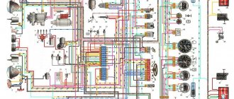
Wiring diagram of the equipment of the VAZ-21102 car
1 - headlight 35 - instrument lighting switch 2 - front brake pad wear sensors 36 - ignition switch 3 - reverse light switch 37 - mounting block 4 - engine cooling system fan electric motor 38 - recirculation valve switch 5 - sound signal 39 - controller heater 6 - right front door locking motor 40 - hazard warning switch 7 - power window relay 41 - heater control lever illumination lamp 8 - 8 A fuse 42 - glove compartment lighting lamp 9 - starter 43 - glove compartment lighting lamp switch 10 - battery 44 — cigarette lighter 11 — generator 45 — on-board control system display unit 12 — windshield washer motor 46 — ashtray lighting lamp 13 — washer fluid level sensor 47 — brake light switch 14 — left front door locking motor 48 — locking motor left rear door 15 - power window switch of the left front door 49 - power window switch of the left rear door 16 - coolant level sensor 50 - power window motor of the left rear door 17 - windshield wiper motor 51 - socket for a portable lamp 18 - recirculation valve 52 - clock 19 - micromotor gearbox for heater flap drive 53 - gearmotor for electric window lift of the right rear door 20 - electric motor for heater 54 - power window switch for the right rear door 21 - trunk lock switch 55 - gearmotor for locking the right rear door 22 - power window switch for the right front door 56 - side turn signal 23 - electric window motor of the right front door 57 - parking brake warning lamp switch 24 - door lock system control unit 58 - driver's seat belt sensor 25 - additional resistor for the heater motor 59 - directional light bulb 26 - brake fluid level sensor 60 - interior light bulb 27 - electric window motor of the left front door 61 — interior air temperature sensor 28 — exterior lighting switch 62 — switch in the front door pillar 29 — instrument cluster 63 — switch in the rear door pillar 30 — rear fog light switch 64 — external rear light 31 — control lamp fog light 65 — interior rear light 32 — rear window heating indicator light 66 — license plate lights 33 — rear window heating switch 67 — trunk light 34 — steering column switch
Diagram of equipment with a carburetor engine on a VAZ 2110
1 – headlight 37 – instrument cluster 2 – front brake pad wear sensor 38 – rear fog light switch 3 – fan motor switch 39 – fog light indicator lamp 4 – engine cooling system fan electric motor 40 – rear window heating indicator lamp 5 – sound signal 41 – clock 6 – generator 42 – rear window heating switch 7 – oil level sensor 43 – steering column switch 8 – carburetor solenoid valve control unit 44 – block for switching wires when installing headlights of another type 9 – heater controller 45 – switch instrument lighting 10 – recirculation valve switch 46 – ignition switch 11 – illumination lamp for heater control levers 47 – connectors for connecting the headlight cleaner wiring harness 12 – switch 48 – socket for a portable lamp 13 – carburetor limit switch 49 – directional light 14 – control sensor oil pressure lamps 50 – brake light switch 15 – spark plugs 51 – interior lamp 16 – carburetor solenoid valve 52 – on-board control system unit 17 – coolant temperature indicator sensor 53 – fuel level indicator sensor 18 – ignition distributor 54 – hazard warning switch 19 – ignition coil 55 – driver’s seat belt sensor 20 – starter 56 – cigarette lighter 21 – heater fan motor 57 – ashtray backlight lamp 22 – additional resistor for heater motor 58 – glove compartment light switch 23 – speed sensor 59 – connector for on-board computer 24 – reverse light switch 60 – glove box lighting lamp 25 – micromotor gearbox for heater flap drive 61 – side turn signal 26 – recirculation valve 62 – switch in the front door pillar 27 – brake fluid level sensor 63 – switch in the rear door pillar 28 – pads for connecting the rear window washer motor 64 – parking brake warning lamp switch 29 – battery 65 – trunk light 30 – windshield washer motor 66 – interior air temperature sensor 31 – washer fluid level sensor 67 – external rear light 32 – level sensor coolant 68 – internal rear light 33 – windshield wiper motor 69 – license plate light 34 – mounting block 70 – block for connecting the rear window heating element 35 – blocks for connecting the warning light harness 71 – block for connecting an additional brake signal 36 – outdoor light switch
Connection diagram of the engine control system 2111 with distributed fuel injection according to the Russian toxicity standards of the VAZ-21102 car
1 – injectors 15 – throttle position sensor 2 – spark plugs 16 – coolant temperature sensor 3 – ignition module 17 – CO potentiometer (not installed on vehicles with a modified control system, CO adjustment is carried out using the DST-2 device through the diagnostic block ) 4 – diagnostic block 18 – idle speed control 5 – controller (since 2000, a modification of the system with M1.5.4N or “January-5.1” controllers has been produced) 19 – knock sensor 6 – cooling system fan electric motor 20 – crankshaft position sensor 7 – block connected to the instrument panel wiring harness 21 – vehicle speed sensor 8 – main relay 22 – immobilizer control unit 9 – fuse connected to the main relay 23 – immobilizer status indicator 10 – electric fan relay 24 – electric fuel pump with fuel level sensor 11 – fuse , connected to the electric fan relay 25 – oil pressure warning lamp sensor 12 – electric fuel pump relay 26 – coolant temperature indicator sensor 13 – fuse connected to the electric fuel pump relay 27 – oil level sensor 14 – mass air flow sensor 28 – knock sensor (installed on cars with a modified control system)
Wiring diagram for connecting door power windows 2110
| Position number on the diagram | Explanation of position |
| 1 | mounting block |
| 2 | ignition switch VAZ 2110 |
| 3 | Right front door power window switch |
| 4 | Right rear door power window switch |
| 5 | Right front door power window motor |
| 6 | Right rear door electric window motor |
| 7 | left rear door power window motor |
| 8 | Left front door electric window motor |
| 9 | left rear door power window switch |
| 10 | left front door power window switch |
| 11 | power window switch |
| A | to power supplies |
| IN | to the instrument lighting switch |
| WITH | the order of conditional numbering of terminals in power window blocks |
21.3. Interactive diagram of the electrical equipment of the VAZ-2110 car
1 – headlight unit 2 – front brake pad wear sensors 3 – fan motor activation sensor 4 – engine cooling system fan motor 5 – sound signal 6 – generator 7 – oil level sensor 8 – carburetor solenoid valve control unit 9 – heater controller 10 – recirculation valve switch 11 – backlight lamp for heater control levers 12 – switch 13 – carburetor limit switch 14 – oil pressure warning lamp sensor 15 – spark plugs 16 – carburetor solenoid valve 17 – coolant temperature indicator sensor 18 – ignition distributor sensor 19 – coil ignition 20 – starter 21 – heater fan motor 22 – additional resistor for heater motor 23 – speed sensor 24 – reverse light switch 25 – micromotor gearbox for heater flap drive 26 – recirculation valve 27 – brake fluid level sensor 28 – connectors for connecting the rear window washer motor 29 – battery 30 – windshield washer motor 31 – washer fluid level sensor 32 – coolant level sensor 33 – windshield wiper gear motor 34 – mounting block 35 – connectors for warning light harness 36 – exterior lighting switch
37 – instrument cluster 38 – rear fog light switch 39 – fog light indicator lamp 40 – rear window heating indicator lamp 41 – clock 42 – rear window heating switch 43 – steering column switch 44 – block for switching wires when installing headlights of another type 45 – instrument lighting control 46 – ignition switch 47 – connectors for connecting the headlight cleaner wiring harness 48 – socket for a portable lamp 49 – front interior lamp 50 – brake light switch 51 – interior lamp 52 – on-board control system unit 53 – pointer sensor fuel level 54 - hazard warning switch 55 - driver's seat belt sensor 56 - cigarette lighter 57 - ashtray illumination lamp 58 - glove compartment lamp switch 59 - socket for connecting the on-board computer 60 - glove compartment lighting lamp 61 - side direction indicators 62 - switches in front door pillars 63 – switches in the rear door pillars 64 – parking brake warning lamp switch 65 – trunk light 66 – temperature sensor for the heating system 67 – external rear lights 68 – internal rear lights 69 – license plate lights 70 – rear heating element glass 71 – block for connecting an additional brake light
In the instrument panel wiring harness, the second ends of the wires of white, black, orange, white with a red stripe and yellow with a blue stripe are connected to each other at the same points.
The electrical circuits of the VAZ-2111 and VAZ-2112 cars differ (with the exception of the engine control system) only in the addition of a tailgate cleaner and washer