02/26/2022 17,497 Cylinder block
Author: Victor
The longevity of the cylinder head is determined by many factors - from proper use and timely maintenance to tightening the bolts of the device in accordance with a certain pattern. Therefore, it is important to know the tightening torque of the VAZ 2109 cylinder head and the sequence of task completion.
[Hide]
When is it necessary to puff?
On most injection and carburetor cars with engines of 8 and 16 valves, there is no need to tighten the cylinder head bolts during operation of the car. But in the case of the domestic “Nine”, it is necessary to correctly stretch the cylinder head and tighten the screws at least when carrying out maintenance of the machine. If it is discovered that moisture has begun to accumulate in the car at the point where the block itself comes into contact with the cylinders, then the bolts will need to be tightened. Since the appearance of moisture in this place indicates a possible leak of motor fluid.
For what reasons may a tightening be necessary:
- The device has been damaged due to engine overheating. Operating the motor in conditions of excessive temperature is fraught with serious malfunctions. The cylinder head of the power unit will need to be repaired, polished and then installed with tightening.
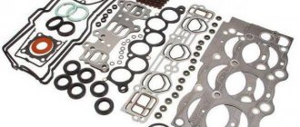
- The cylinder head gasket is damaged or has lost its tightness. If this problem is not resolved in a timely manner, engine fluid will enter the cooling system. A damaged gasket must be replaced. After changing the part, the head bolts must be tightened correctly.
- The engine has run for a certain time.
Common Mistakes
Despite the fact that automakers clearly indicate the procedure and nuances of tightening the cylinder head, many car enthusiasts make mistakes when assembling the engine. The most common of them are:
- Pouring oil into the mounting holes to lubricate the threads (the liquid is incompressible, so poured oil will not allow the head to be properly tightened);
- Over-tightening (exceeding tightening forces leads to damage to the cylinder head and the fasteners themselves);
- The use of damaged or inappropriate keys (the edges of the bolt heads may be torn off, after which it will be problematic to tighten or unscrew them normally);
- Use of unsuitable bolts as replacements (fasteners from different engines may differ in length, thread spacing, head height and diameter);
To avoid problems in the future, you should use only fasteners designed for a specific engine and fully comply with the work conditions.
How is the tightening torque of VAZ 2109 bolts adjusted?
If it is necessary to tighten the cylinder head of a Nine engine, it is important to observe not only the strength and degree of tightening of the bolts, but also other conditions. Below we will look at how to correctly stretch the cylinder head on a VAZ 2109.
What will you need?
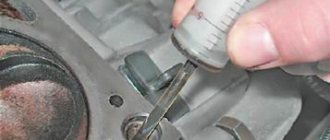
The procedure for tightening fasteners after removal and repair, as well as when installing the cylinder head, is carried out exclusively with a torque wrench.
A dynamometer is a tool designed to tighten the cylinder head screws of various engines.
In addition to the key, you will also need a caliper or a regular ruler.
User Marat Ibatullin made a video in which he clearly showed how the task of tightening the screws is performed.
Scheme of work
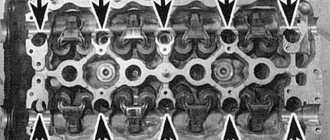
The order of tightening the bolts on cars with an injector or carburetor engine is determined by the manufacturer and is indicated in the service book for the car. According to the diagram, the pulling procedure begins with the central two cylinder head bolts.
The cylinder head bolts must be tightened as follows:
- First, you need to twist the screws with a force in Newtons of 2.0 kg/cm.
- Then the bolts are tightened to a torque of 7.5-8.5 kg/cm.
- After this, all screws must be tightened 90 degrees.
- At the end, each bolt is rotated 90 degrees again.
How to tighten the head screws of a VAZ 2109 block with your own hands:
- The torque wrench holder is placed in the zero position. This indicates that the instrument data corresponds to the moment of the initial position.
- Evaluate the indicators on the key before starting the tightening procedure.
- The tool holder can now be rotated. Monitor the readings as you complete the task.
- If it happens that the torque does not change during tightening, then the head mount may be stretched. This is quite normal, as it should be. First, use a wrench to tighten the screws to 2 kg/cm. Follow the tension sequence shown in the diagram.
- At the next stage, the covering is performed again in the same sequence. Only now the bolts need to be pulled to approximately 8 kg/cm.
- At the end of the procedure, the screws must be tightened once 90 degrees in a circle, and then again 90 degrees.
Channel RUS13 in its video showed how to install the cylinder head on a VAZ 2109 engine and tighten the bolts.
Tightening rules
What nuances should be taken into account when carrying out this procedure:
- Observe the appropriate tightening torque for the VAZ 2109 cylinder head.
- The use of wrenches and other tools is not allowed, since the degree of tension can only be determined using a dynamometer.
- To perform tensioning, only working screws are allowed. The bolts must meet the requirements of the power unit installed on the machine.
- Before completing the task, make sure that the holders are in good working order.
- If the cylinder head has been replaced or repaired, then the old bolts cannot be used for tension; new ones must be purchased. On sixteen-valve power units, it is allowed to re-use screws to fix the block head, but only if the length of the parts is no more than 9.5 cm. It is necessary to measure the length of the screw only with a washer. If the bolts are larger than 9.5 cm, they must be replaced.
- If the vehicle is equipped with an aluminum head, then the cylinder head is fixed with TTU type screws. They cannot be tightened because they are screwed into a thread with a certain degree.
- When purchasing a cylinder head gasket, you need to pay attention to the manufacturer's specifications. They often prescribe a certain tightening ratio required for specific gaskets. Please note that the indicated moment of force should not diverge much from the one applied during the work process.
- In power units equipped with aluminum cylinder heads, the tightening procedure is carried out on a cold engine. As for cast iron engines, in such internal combustion engines it is necessary to perform the tightening while it is hot.
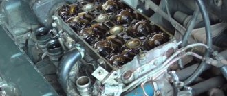
Disassembly and assembly of the cylinder head
Disassembly. If only one part needs to be replaced, then you do not have to completely disassemble the cylinder head and remove only what is necessary for replacement.
Place the cylinder head on the stand, disconnect the hose from the warm air intake, unscrew the nuts and remove the carburetor with the spacer, the carburetor heat shield, and then the intake pipe and exhaust manifold (the warm air intake is removed at the same time).
Remove the engine cooling jacket outlet pipe. Unscrew the coolant temperature gauge sensor, oil pressure warning light sensor and spark plugs.
Unscrew the nuts and remove the fuel pump with gaskets, spacer and pusher. Disconnect the auxiliary unit housing from the cylinder head.
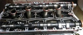
Rice. 2.54. Dismantling the cylinder head: 1 – cylinder head; 2 – camshaft; 3 – rear camshaft bearing housing; 4 – gasket; 5 – cylinder head cover; 6 – front camshaft bearing housing; 7 – oil seal
Remove bearing housings 3 and 6 (Fig. 2.54) of the camshaft. Remove camshaft 2 from the cylinder head supports and remove oil seal 7 from it.
Rice. 2.55. Details of the valve drive mechanism: 1 – valve; 2 – guide sleeve; 3 – retaining ring; 4 – oil deflector cap; 5 – spring support washer; 6 – internal spring; 7 – outer spring; 8 – spring plate; 9 – crackers; 10 – adjusting washer; 11 – pusher
Rice. 2.56. Compression of valve springs: 1 – device 67.7823.9505
Remove the valve pushers 11 (Fig. 2.55) from the holes of the cylinder head with adjusting washers 10. Free the valves from the crackers 9, compressing the valve springs with tool 67.7823.9505 (Fig. 2.56). Remove the springs with plates. Turn the cylinder head and remove the valves from the bottom. Remove the oil seals from the guide bushings and the spring support washers.
Assembly. Install the spring support washers. Lubricate the valves and new oil seals with engine oil (old ones are not allowed). Using mandrel 41.7853.4016, press the caps onto the guide bushings. Insert the valves into the guide bushings, install the springs and spring retainers.
Compressing the springs with tool 67.7823.9505 (see Fig. 2.56), install the valve cotters. Insert valve pushers with adjusting washers into the holes of the cylinder head.
Rice. 2.57. Camshaft bearing housing installation sleeves
Clean the mating surfaces of the cylinder head and bearing housings from old gasket residue, dirt and oil. Install the installation bushings (Fig. 2.57) of the camshaft bearing housings.
Rice. 2.58. Position of the cams of the first cylinder when placing the camshaft in the cylinder head supports
Lubricate the bearing journals and cams of the camshaft with engine oil and place it in the cylinder head supports in such a position that the cams of the first cylinder are directed upward (Fig. 2.58).
Rice. 2.59. Applying sealant to the surface of the cylinder head
On the surface of the cylinder head mating with the bearing housings, in the area of the outer camshaft supports, apply sealant type KLT-75TM or similar sealant type TB-1215 (Fig. 2.59).
It is allowed to start the engine no earlier than 1 hour after applying the sealant.
Install the bearing housings and tighten the nuts in two steps:
Rice. 2.60. Procedure for tightening the camshaft bearing housing nuts
1. Pre-tighten the nuts in the sequence shown in Fig. 2.60, until the surfaces of the bearing housings touch the cylinder head, making sure that the mounting sleeves of the housings fit freely into their sockets.
2. Finally tighten the nuts to 21.6 N·m (2.2 kgf·m) in the same sequence.
Immediately after tightening the bearing housing nuts, carefully remove any remaining sealant squeezed out of the gaps during tightening in the areas adjacent to the cylinder head cover gasket and the accessory housing. Left untreated polymerized sealant residues in these areas will result in oil leakage through the seals.
Using mandrel 67.7853.9580, press in a new camshaft oil seal, having previously lubricated it with engine oil.
Install the cooling jacket outlet pipe with gasket and the accessory housing with the O-ring.
In accordance with the instructions in the “Fuel Pump” chapter, install the heat-insulating spacer with gaskets, the pusher and the fuel pump.
Rice. 2.33. Installation of the intake pipe and exhaust manifold: 1 – exhaust manifold; 2 – bracket for the supply pipe of the coolant pump; 3 – inlet pipe; 4 – warm air intake
Place gaskets on the cylinder head studs and install the exhaust manifold and intake pipe. Secure them with nuts together with warm air intake 4 (see Fig. 2.33).
Install the carburetor heat shield, spacer and carburetor. Secure it with nuts and close the carburetor with the technological cover.
Wrap the spark plugs and coolant temperature gauge and oil pressure warning light sensors into the cylinder head.
Adjust the valve clearances after installing the cylinder head on the engine.
Video “Visual aid for tightening cylinder head screws on a VAZ 2109”
Engine Repair Channel! And interesting! published a video demonstrating the procedure for tightening the cylinder head bolts on a Nine with a description of all the nuances of this process.
Do you have any questions? Specialists and readers of the AUTODVIG website will help you ask a question
Was this article helpful?
Thank you for your opinion!
The article was useful. Please share the information with your friends.
Yes (83.33%)
No (16.67%)
X
Please write what is wrong and leave recommendations on the article
Cancel reply
Rate this article: ( 12 votes, average: 4.83 out of 5)
Discuss the article:
Replacement
To change the gasket, you will need to dismantle the assembly, get rid of the worn cylinder head gasket and reassemble the structure in the reverse order, following the recommendations regarding the tightening torques of the cylinder head bolts. We will tell you about all this in more detail.
- Disconnect the wiring from the coolant temperature sensor and emergency oil pressure sensor.
- Remove the thermostat, just remember to drain the coolant first.
- Remove the air filter housing. There is no need to remove the carburetor, because it will not interfere with replacing the gasket.
- Disconnect the exhaust pipe from the exhaust manifold.
- Remove the camshaft drive gear after first setting the piston of the first cylinder to the TDC position. Now you can remove the protective casing of the camshaft drive belt, loosen the gear fixing bolts, securing the gear from turning.
- Remove the camshaft drive belt. Then you can completely unscrew the mounting bolts and remove the gear.
- Press the latch to disconnect the wiring block from the ignition distributor.
- Similarly, turn off the central high voltage.
- Loosen the clamps to remove the fuel supply hose from the fuel pump.
- Disconnect the throttle and air damper drive rods from the carburetor.
- Disconnect the power supply from the solenoid valve.
- Remove the vacuum booster hose from the intake pipe fitting.
- Disconnect the tube from the vacuum ignition corrector.
- Loosen the tension on the clamps to remove the interior heating hoses from the pipes.
- Remove the cylinder head. Using a socket with an extension, the mounting bolts are unscrewed.
- Rock the head a little jerkily, then remove the element.
- Remove the old gasket, clean it of any remaining rubber seal and other contaminants. Wipe dry thoroughly, after which you can reassemble.
- Before assembly, check whether the length of the cylinder head bolts is within the normal range. Ideally, their length is 135.5 millimeters. If the bolts have lengthened during use, then all bolts will have to be replaced.
Replacement procedure