From time to time, the cylinder head gasket may fail due to wear and tear of its material or burnout. The main signs that it is time to replace the gasket with a new one are the appearance of local leaks of oil and coolant at the point of contact between the cylinder head and the engine. Tightening torque of the cylinder head VAZ 2114 8 valves: consider the subtleties of the process.
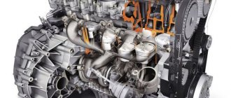
Cylinder head gaskets
It should be remembered that when replacing a gasket, not only the tightening torque of the VAZ 2114 cylinder head is important, but also the entire sequence of operations - after all, the replacement itself is a very important and serious procedure, errors during which can lead to engine malfunction.
Required Tools and Process
From time to time, the cylinder head gasket may fail due to wear and tear of its material or burnout. The main signs that it is time to replace the gasket with a new one are the appearance of local leaks of oil and coolant at the point of contact between the cylinder head and the engine. Tightening torque of the cylinder head VAZ 2114 8 valves: consider the subtleties of the process.
It should be remembered that when replacing a gasket, not only the tightening torque of the VAZ 2114 cylinder head is important, but also the entire sequence of operations - after all, the replacement itself is a very important and serious procedure, errors during which can lead to engine malfunction.
In order to do it correctly, you will need:
- set of socket heads;
- extension;
- ratchet/wrench;
- torque wrench.
The replacement process itself should be performed according to the following scheme:
- Disconnect the wires leading to the emergency oil level and coolant temperature sensors.
- Drain the coolant.
- Remove the thermostat.
- Remove the air filter housing.
- Disconnect the exhaust pipe inlet from the manifold.
- Remove the casing, as well as the camshaft belt itself.
- Disconnect the drive rods of both dampers from the carburetor.
- Disconnect the wires going to the cylinder head.
- Disconnect the hoses suitable for the cylinder head by loosening their clamps.
- Remove the cylinder head.
- Remove the worn gasket.
- Clean the contact surface of the cylinder head from any remaining gasket material.
Installing the gasket and mounting the cylinder head in place is carried out in exactly the same sequence, but in reverse order. At the same time, it is worth paying close attention to such a factor as the tightening torque of the cylinder head of the VAZ 2114 8 valves - we will talk about it below.
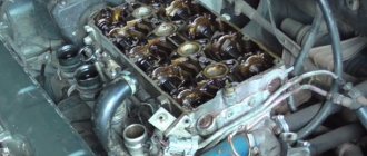
Signs of gasket failure
Signs of a cylinder head gasket failure
The main signs of gasket failure are:
- the appearance of a white emulsion on the dipstick when checking the oil level. This deposit on the dipstick means that the gasket has ruptured between the holes through which oil and coolant pass;
- thick white smoke. Indicates that there is a breakthrough in the gasket between the hole through which the coolant flows and one of the cylinders. In this case, the white color of the exhaust gases is given by the evaporating liquid that has entered the cylinder. Additionally, placing your hand near the exhaust pipe while the engine is running will help you verify that the gasket is broken. The coating remaining on the hand should be tasted on the tongue - if it is sweet, then the liquid is getting into the cylinder;
- the presence of oil stains on the surface of the coolant in the expansion tank. Multi-colored oil spots will indicate that, as a result of a breakdown, oil began to enter the channel with the passing coolant;
- bubbles in the expansion tank when the engine is running. This sign will indicate that, as a result of a gust, exhaust gases penetrate into the coolant channel;
- a sharp whistle when the engine is running, accompanied by oil leaks on the cylinder block. This is the clearest sign that there has been a breakdown of the gasket with an outlet. It occurs rarely, often after the engine has been modified with preliminary removal of the head;
- the most hidden type is a breakdown between the cylinders. There are no particularly obvious signs, except for a drop in power and an increase in fuel consumption, which may be the result of a malfunction of other mechanisms. Only a compression test will help verify the presence of such a breakdown, and even then not always. The same misalignment of the valves can give such symptoms;
If such symptoms appear, the only option for eliminating this malfunction is to replace the cylinder head gasket of the VAZ 2114.
It is noteworthy that this gasket is disposable and is replaced every time, so any modification to the engine associated with removing the head must be accompanied by a replacement.
How to tighten cylinder head bolts correctly?
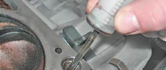
Before you begin installing the cylinder head, you should first pay attention to the condition of its bolts. They must have a good thread and the length meet the required standards.
The normal overall length of the cylinder head bolt is 135.5 mm. If the bolts removed during gasket replacement meet this parameter, they can be reused. If the bolts have lengthened during engine operation, then they can no longer be used and new ones should be purchased.
Having dealt with the bolts in this way and installing them in place, you should proceed to tightening. It must be done only with a torque wrench. Tightening bolts “by eye” can lead to very serious consequences, including damage to the engine itself.
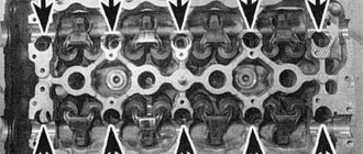
And so, how to stretch the head onto a VAZ 2114 correctly? Firstly, you should remember that you should start tightening the bolts from the center to the edges.
Secondly, tightening should be done in four stages (each of which is performed in exactly the same sequence as indicated in the diagram above).
At the first stage, we tighten each of the bolts with a torque wrench with a force equal to 2 kgf/cm2.
At the second stage, we tighten all the bolts with a force of 8 kgf/cm2.
At the third stage, we tighten the bolts, turning each of them at an angle of 90 degrees.
At the fourth stage, we again turn each of the bolts (still following the diagram given at the beginning) at an angle of 90 degrees.
Once all four steps are completed, tightening the cylinder head bolts can be considered complete.
The tightening of cylinder head bolts should be taken as seriously as possible. All its stages must be performed strictly in the same order and with equal effort at each of them. Failure to comply with this rule can lead to rapid wear of the gasket and the appearance of oil and coolant leaks.
Self-replacement - what needs to be taken into account?
The replacement process is considered quite simple, but you need to understand that it is not always possible to carry out the work smoothly.
That is why when carrying out work you should follow simple tips that will help you avoid mistakes:
- When removing the lid, you should wash it in turpentine.
- The optimal solution would be to use high-quality gaskets.
- All parts used must be clean; when carrying out work, experts advise wiping the edges of parts to remove any existing oil.
- During installation, you can use a sealant; it is applied to the joints.
- After the replacement is completed, you need to check the oil level.
- To check the system, you need to start the car; carry out a second inspection after making the first trip.
- The groove under the gasket should be cleaned as thoroughly as possible.
conclusions
Replacing the head gasket on a VAZ-2114 is quite difficult, since you need to know the design features of this engine, as well as have experience in performing such operations on similar engines.
The choice of gasket should be approached seriously and carefully, since the normal operation of many components depends on its condition. If the process described in the article seems quite complicated and the motorist is not able to carry out the operation on his own, then it is recommended to contact a car service center, where they will help and do everything quickly and efficiently.
Video on the topic:
Hello people, tell me which head to unscrew the cylinder head bolts with, I don’t have a hex head, but some kind of sprockets. There are no such people at home or at work to take and not make a mistake. Does the marking seem to be E12, E14 or E16? VAZ 2109, injector. What is the key for the cylinder head.
Similar articles
17 comments on “What is the key for the cylinder head. Which head should I use to unscrew the cylinder head bolts?
With a regular 13mm head you can unscrew it
Andrey, I tried the head on 13, it just scrolls, on 12 it does the same, and on 11 it fits exactly. Only the bolt head is made in the form of an asterisk, and I am not sure that a regular 11 head is the key that is needed to unscrew these bolts.
Tightening torque of the cylinder head VAZ 2114 8 valves: correct operation with a torque wrench
A tool such as a torque wrench, which allows you to tighten bolts with equal force, requires great care in operation and certain skills.
An approximate sequence for tightening bolts with this wrench is as follows:
- set the holder to the “zero” position;
- begin smooth rotation of the instrument, while simultaneously monitoring its readings;
- if the tool rotates (especially at the initial stage of tightening) without changing the torque on the indicator, this may indicate a slight internal stretch of the fasteners. This phenomenon is absolutely normal and the rotation of the tool should be continued;
- When the tightening torque corresponding to the required one is reached, the movement of the tool should be stopped.
Instead of using a torque wrench, you should not use any other tool (including a mechanized one, with the ability to regulate the tightening force). After all, only with a wrench can you achieve absolutely precise and smooth tightening of the bolts, thanks to which the gasket will be evenly pressed over the entire surface of the block. This will help maximize its service life, avoid burnouts, oil leaks and coolant leakage.
Typical breakdowns
The very first 1.5 liter engine 2114 has disadvantages:
- periodic valve adjustment;
- unreliable injection system;
- loosening the exhaust manifold nuts;
- Leaking gaskets of the fuel pump, distribution sensor of the ignition system.
The next 1.6 liter engine does not cause any particular problems for the owner, with the exception of high vibration and noise loads. The weak point traditionally remains the valves, which have to be constantly adjusted.
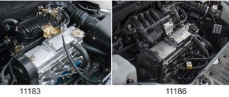
The internal combustion engine from Lada Kalina 11183 was installed on the fourteenth model solely to meet Euro-3 standards. It has typical disadvantages for a linear series and is no different.
The first sixteen-valve engine 21124 does not bend the valves, the gaps in which are adjusted by hydraulic pushers. However, the belt needs to be tightened after 15,000 km due to the large number of attachments. The second and last in the line of fourteenth ICE models, ICE 21126, has increased power. In addition to typical malfunctions, if the timing belt breaks, the piston will bend the valve due to insufficient recess depth.
Procedure for replacing the cylinder head gasket on a VAZ 2109-2108
The gasket may remain either on the surface of the head or stick to the block itself. You can try to remove it by hand without using any tools, and if that doesn’t work, you can carefully pry it off with a flat-head screwdriver without damaging the surface of the part.
The engine block also needs to be cleaned and then a new gasket installed on it.
Of course, it will be necessary to first carry out some preparatory procedures, without which it will be impossible to remove the head.
- First, you need to remove the air filter housing
- Then disconnect all fuel hoses and power wires from the carburetor or injector (depending on the type of engine)
- , although this is not a prerequisite - it will be enough to disconnect the high-voltage wires
In general, it is necessary to free the head from everything unnecessary so that during dismantling there are no unnecessary problems. Of course, if you decide to completely replace it or repair it, then you will have to perform more operations, both the carburetor and the manifolds. Well, if it’s just a matter of gasketing, then you can get by with a minimum of actions.
Valve stem seals
While adjusting the valves, it is quite possible that you had no idea that you were next to another very important element of the gas distribution mechanism - the valve stem seals.
Oil scraper seals are located on the valve stems of the gas distribution mechanism
Purpose of valve stem seals
While the engine is running, the camshaft, rocker arms, valve springs and valve tops operate in an oil mist. Oil is deposited on all parts and mechanisms located under the valve cover. Naturally, it also ends up on the top of the valves, called stems.
Under the influence of gravity, the oil will tend to flow into the combustion chamber. As you know, it shouldn't be there. Oil seals are designed to prevent oil from flowing down the valve stem into the engine combustion chamber.
Engine malfunctions associated with worn caps
The sole purpose of the oil seal is to prevent oil from draining into the engine combustion chamber. Over time, the rubber of this element loses its functions and is destroyed under the influence of an aggressive environment. This leads to the penetration of oil into the air-fuel mixture, where it burns successfully.
A working engine should have oil consumption of about 0.2 - 0.3 liters per 10 thousand kilometers. With worn valve stem seals, it can reach one liter per thousand kilometers.
Oil burning in the cylinders:
- clogs and destroys catalytic converters and particulate filters (devices that reduce the content of harmful substances in exhaust gases), which themselves are very expensive;
- causes overheating and premature failure of engine exhaust valves;
- greatly increases exhaust smoke;
- increases the risk of engine oil starvation due to lack of oil.
The service life of valve stem seals on domestic cars fluctuates around 80 thousand kilometers. This parameter very much depends on the quality of the caps themselves and the oil used.
What components are best to use?
Today, the greatest trust among car enthusiasts and mechanics is in the products of such well-known brands as Corteco and Elring - these brands have proven themselves to be the best in the production of gaskets, oil seals, seals, and valve stem seals.
There are products from domestic manufacturers on the market. Their quality varies greatly, but nevertheless does not reach the quality of the products of leading companies.
How to change valve stem seals
The topic of replacing valve stem seals is extensive and worthy of a separate article. Briefly it is done like this.
- Remove the valve cover.
- Remove the camshaft sprocket.
To remove the camshaft sprocket, you need to unscrew the bolt holding it with a lock washer.
- Remove the camshaft from its beds.
To remove the camshaft, you need to unscrew the bolts securing its bearing housing
- Support the valves with a tin rod through the spark plug well.
To prevent the valves from falling down, they need to be supported with a tin rod.
- Dry the valve.
Squeeze the valve spring and remove the crackers from the groove.
- Replace the oil seal.
The old oil seal can be removed using two screwdrivers.
Cars VAZ-2115i-14i-13i
The tightening torques for threaded connections on VAZ-2115 (2113, 2114) vehicles are given in the table below.
- The given values of tightening torques for threaded connections can be rounded to tenths within the tolerance.
- The cylinder head mounting bolts must be tightened in four steps: 1 – to a torque of 20 Nm (2 kgf); 2 – torque 69.4–85.7 (7.1–8.7 kgf); 3 – turn 90°; 4 – turn it 90° again.
Tightening torque, Nm (kgf-m)
Procedure for replacing the cylinder head gasket on a VAZ 2109-2108
At the end of the operational period or if the integrity of the cylinder head gasket is damaged, the element must be replaced.
The main sign of a malfunction or gasket wear is the formation of coolant and oil leaks at the junction of the engine block and the cylinder head.
Cylinder head seals
Replacement
To change the gasket, you will need to dismantle the assembly, get rid of the worn cylinder head gasket and reassemble the structure in the reverse order, following the recommendations regarding the tightening torques of the cylinder head bolts. We will tell you about all this in more detail.
Cylinder head seals
If you detect a leak of engine oil or coolant at the junction of the head and the cylinder block, remove the head and replace its gasket. A leak can also occur due to warping of the block head due to overheating.
You will need: a torque wrench, keys “13”, “17”, “19”, socket heads “10”, “13”, “17”, “Togh”, screwdriver.
Warning! The head gasket is a one-time use unit, so the gasket must be replaced each time the head is removed.
1. Disconnect the wire from the “-” terminal of the battery.
2. Set the piston of the 1st cylinder to the TDC position of the compression stroke (see “Installing the piston of the 1st cylinder to the TDC position of the compression stroke”).
4. Reduce the pressure in the power system if the work is performed immediately after a trip (see “Reducing pressure in the power system.”
5. Disconnect the exhaust pipe of the muffler from the exhaust manifold (see “Replacing the exhaust pipe”.
6. Remove the cylinder head cover (see “Replacing the cylinder head cover gasket”).
7. Disconnect the wiring harness block from the mass air flow sensor, loosen the clamp securing the air supply pipe to the throttle body and remove the pipe with the air filter housing and the air intake hose from the throttle body (see “Removing and installing the air filter”).
8. Unscrew nut 1 securing the bracket for the water pump supply pipe. Loosen nut 2 securing the inlet pipe bracket to the exhaust manifold.
9. Move the bracket to the side.
10. Loosen the clamps.
11. ...and disconnect the inlet and outlet hoses of the cooling system from the throttle body.
12. Loosen the clamp securing the vacuum brake booster hose to the fitting on the receiver...
13. ...and remove the hose.
14. Turn the throttle drive sector all the way and disconnect the throttle drive rod from it.
15. Unscrew the two nuts securing the tips of the “mass” wires to the rear cover of the cylinder head...
16. ...and remove the wires from the studs.
17. Unscrew the nut of the lower fastening of the spacer 1 and remove the bolt of the lower fastening of the spacer 2...
18. ...unscrew the nuts of the upper fastenings of the intake manifold struts on the right...
19. ...and on the left side, remove the spacers.
20, Disconnect the wiring harness connectors from the crankcase oil level sensors...
21. ...from the throttle position sensor...
22. ...from the idle air control...
23. ...from the injector wiring harness...
24. ...from the coolant temperature sensor...
25. ...from the crankshaft position sensor and the knock sensor.
26. Disconnect the wire connectors from the coolant temperature gauge sensor...
27. ...and from the oil pressure sensor.
28. Disconnect the high-voltage wire tips from the spark plugs.
29. Pull the wiring harness out from under the receiver.
30. Remove the three screws securing the front camshaft drive belt cover, remove the cover...
Warning! It is forbidden to turn the crankshaft and camshaft before installing the camshaft belt.
32. Secure the camshaft toothed pulley from turning, remove the bolt securing the pulley to the camshaft...
33. ...and remove the bolt and washer.
34. Remove the pulley from the camshaft. Do not damage the camshaft oil seal.
Note. If the key does not sit tightly in the groove of the camshaft nose, remove it so as not to lose it.
35. Unscrew the nut securing the rear camshaft drive cover at the top of the cylinder head.
36. Remove four bolts (three of them also secure the water pump) and remove the rear cover (see “Engine repair (disassembly, troubleshooting, assembly)”).
37. Unscrew the nut securing the “mass” wire...
38. ...and remove the wire from the stud securing the exhaust pipe of the cooling system to the cylinder head.
39. Loosen the clamps and remove the radiator inlet pipe 2, the inlet hoses of the throttle unit 4 and the heater 3 from the outlet pipe, disconnect the thermostat 5 along with hose 1.
40. Unscrew the fastening nuts and disconnect the fuel supply and drain hoses from the fuel pipes, holding the hoses from turning with a second wrench.
41. Please note that there are O-rings installed on the fuel pipes.
After disconnecting each hose, remove the O-ring from the tube. Replace heavily compressed or torn rings.
42. Loosen the ten bolts securing the head of the unit in the order shown, then completely unscrew the bolts securing the head, remove them along with the washers and remove the head.
Note. It is necessary to unscrew the cylinder head mounting bolts using a special socket head “Togh”.
Warning! Do not jam a screwdriver or other tools between the cylinder head and the cylinder block.
Helpful advice. To remove the cylinder head from the gasket, insert a screwdriver under the exhaust manifold. Using it as a lever, lift the head.
43. Remove the head gasket.
Note. The cylinder head bolts become stretched with repeated use. Replace with new bolts longer than 135.5 mm. Before installing the cylinder head, lubricate the bolts with a thin layer of engine oil.
44. Clean the mating surfaces (they must be dry and clean) of the cylinder head and cylinder block and remove oil from the threaded holes in the block for the head mounting bolts.
45. Install a new head gasket on the block (the gasket must be dry and clean) along the installation sleeves so that the hole for the oil passage in the gasket (with copper edging) is between the 3rd and 4th cylinders.
1 - torque 20 N-m (2 kgf-m);
2 - torque 69.4-85.7 Nm (7.1-8.7 kgf-m);
3 - tighten the bolts 90°;
4 - finally tighten the bolts 90°.
47. Install the parts on the cylinder head and connect hoses and wires to it in the reverse order of removal. Install the camshaft pulley with the protruding part of the hub facing the engine.
Check and, if necessary, adjust the clearances in the valve drive (see “Adjusting the clearances in the valve drive”). Adjust the tension of the camshaft drive belt (see “Replacing the camshaft drive belt and adjusting the belt tension”).
Withdrawal procedure
- We prepare the car for work and disconnect the wire terminal from the negative terminal of the battery
- Drain the coolant from the engine
- Removing the air filter
- Remove the intake manifold and exhaust manifold from the engine. If necessary, the cylinder head can be removed complete with parts of the power system and exhaust manifold.
- Removing the cylinder head cover
- On engines with phased fuel injection, disconnect the wire block from the camshaft position sensor
- We disconnect the wire tips from the coolant temperature sensor. For ease of operation, we disconnect the wiring harness block from the knock sensor and move the sensor wire harness to the side.
- Disconnect the wire tip from the coolant temperature gauge sensor
Using a 13 mm socket wrench, unscrew the nut securing the “mass” wire to the engine and remove the wire tip from the stud.- Using a 13 mm socket wrench, unscrew the two nuts securing the pipe.
- We remove the pipe from the cylinder head studs and, without disconnecting the hoses, move it to the side.
- Remove the sealing gasket from the studs.
- Removing the camshaft pulley
- Unscrew the nut and bolt of the upper fastening of the rear timing belt cover
- Remove the oil level indicator.
- Using a Torx E14 socket wrench with a narrow head, unscrew the ten bolts securing the cylinder head. Some of the cylinder head bolts can only be unscrewed with a socket wrench with a narrow head. If you do not have such a key, remove the camshaft and then unscrew the cylinder head bolts.
- Pulling the rear timing belt cover slightly to the side, remove the cylinder head.
- Removing the cylinder head gasket
- We take out the two guide bushings.
Reinstalling the head
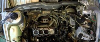
Photo and video instructions for those who plan to independently remove and install the cylinder head on a VAZ 2114, 13, 15.
The cylinder head is removed to repair it, to replace the head gasket, and also during major engine overhauls.
- We wash the cylinder head from dirt and deposits with kerosene or diesel fuel.
We remove any remaining oil and coolant from the threaded holes of the cylinder block (under the cylinder head bolts).- We clean the landing surfaces of the head and cylinder block from the remnants of the old gasket, and degrease the surfaces with a solvent. Always use a new gasket when installing the cylinder head. Oil should not come into contact with the surface of the gasket.
- We install the head guide bushings into the mounting hole of the cylinder block.
Sequence of tightening the cylinder head bolts - We place the gasket on the cylinder block, and the guide bushings should fit into the corresponding holes in the gasket.
- We install the head on the cylinder block. By slightly moving the head from side to side, we ensure that the guide bushings fit into the corresponding holes in the head. Reuse of cylinder head bolts is permitted only if their length does not exceed 135.5 mm.
- Using a caliper or a mechanic's ruler, measure the length of the bolts. Bolts longer than 135.5 mm are replaced.
- Before screwing, dip the threaded part of the bolts into engine oil, then let the oil drain, waiting for about half an hour.
- Install bolts and washers into the holes in the head.
- Using a torque wrench, tighten the head mounting bolts (in the sequence shown in the photo) in four steps: – tighten the bolts to a torque of 20 Nm (2 kgf m); – tighten the bolts to a torque of 69.4–85.7 Nm (7.1 –8.7 kgf m);– turn the bolts by 90°;– turn the bolts again by 90°.11. We perform further assembly in reverse order.
10. Loosen the clamps.
Now you can carefully install the cylinder head in its place, making sure that at this moment the gasket does not slip out or move to the side. Of course, the guides fix it, but you should still be extremely careful.
Now regarding the force with which it is necessary to tighten the bolts. This should be done in 4 steps:
- First, a torque of 20 Nm
- Second reception with a torque of 75-85 Nm
- Tighten each bolt another 90 degrees.
- Finally turn it 90 degrees.
After this, all that remains is to install all the equipment removed from the car, fill in the coolant, connect all the sensors, wires and hoses and check the work done. Usually everything becomes visible immediately after pouring antifreeze. If wet marks appear at the junction of the head and block, you can take everything back and do the whole job again! But I hope that this will not happen in your practice! Happy renovation!
Assembly Features
Before assembly, you should check the bolts securing the head to the hood; their length should not be more than 13.5 cm; if they are longer, they can no longer be used.
You should also check the flatness of the head. If it was overheated, it is possible that it was warped and will require repair in the form of trimming the plane.
During assembly, the head bolts are tightened in a certain sequence and with a strictly defined tightening torque. Next, everything is assembled in the reverse order of disassembly.
Disassembly is also carried out in the same sequence if the power plant is being modified.
Conversion kit for an 8-valve injection engine to a 16-valve engine. You can check prices here www.tltzap.ru/price.html#1
The kit includes: price: 1. Cylinder head 21126 assembled.___________________17,000 2. Timing casing.___________________________1000 3. Timing rollers___________________________500 4. Timing belt 2112______________________________250 5. Water pump 2112________________550-1000 6. Bare fuel rail with tube 7. Injector wiring 8. Pistons 21124 82.0____________________1000 9. Piston pins 2110______________50-75 10. Retaining rings_____________1-25 for 1 piece 11. Modified cylinder head bolts 2108___________40 for 1 piece 12. Intake receiver____________________4500 13. Exhaust manifold gasket_______2-36 for 1 piece 14. Exhaust manifold (spider 4 -2-1)_______1800 15. Modified cylinder head gasket__________ 16. Oil dipstick________________________75 17. Aluminum breather____________780 18. Lower breather hose (thick) 2112_____30 19. Damper 2112_______________________550 20. Crankshaft pulley 2112____________870 2 1. Valve cover 21126______________1400 22. Timing pulleys__________________________950 23. Coils ignition 24. Ignition coil wiring 25. Spark plugs 2112 26. Crankshaft bolt 27. Camshaft bolts 28 Camshaft bolt washers 29. Valve cover bolts 30. Timing roller nuts 31. Timing roller washers 32. 4mm alignment washers for the rollers. 33. Timing cover mounting bolts. PS: Pistons can be replaced with sizes 82.4 and 82.8.__770-2950 per set