To control the fuel in tanks, special devices are used: fuel level sensors, or FLS. They measure the amount of gasoline, oil or diesel fuel. Most often, FLS are installed on cars, but they are also in demand at fuel depots.
The sensor's task is to measure the fuel level, recalculate its volume and transmit information to the dispatcher. Thanks to the FLS, vehicle owners monitor fuel consumption and prevent gasoline from being drained: if at some point the fuel level in the tank drops sharply, the dispatcher will notice it. The sensor can complement other controllers or serve as an independent device, but it must be connected to the machine monitoring system. It is she who transmits and stores information about changes in the fuel level in the tank.
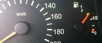
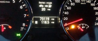
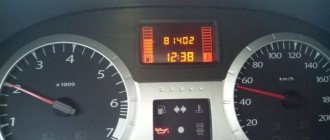
The FLS is installed through a standard hole in the tank or a hole of suitable diameter for installation is specially prepared. Most often, the device looks like a rod or a float, but this is high-precision equipment that can be used not only on passenger cars, but also on trucks, special equipment or stationary objects. The sensor can be connected to the fuel level indicator on the dashboard. Thanks to this, the driver can monitor consumption while driving and make timely stops for refueling.
Why is FLS necessary?
The cost of purchasing fuel is one of the largest items when maintaining a vehicle. Using a fuel level sensor helps not only record the amount of fuel at a given point in time, but also:
- determine fuel consumption for a certain time period;
- calculate average fuel consumption, for example, per hundred kilometers;
- control the timeliness of fuel refueling;
- identify unauthorized fuel drains and misuse of official vehicles.
All this allows for strict control of fuel consumption, finding ways to save money, and planning routes based on the available amount of fuel. Such measures help reduce the cost of purchasing fuel and maintaining the vehicle fleet as a whole.
Float FLS: features
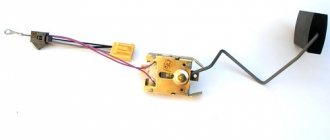
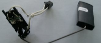
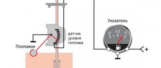
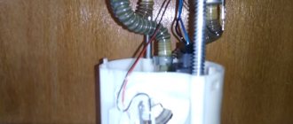
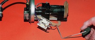
Float sensors are standard and are installed as part of vehicle production. The working element of the device is a float, which is immersed in fuel and connected to a potentiometer. When the fuel level decreases or increases, the resistance of the potentiometer changes, and accordingly, the output voltage changes. Data on the amount of fuel is transmitted to a pointer located on the dashboard.
Potentiometric sensors are divided into lever and tubular. In the first case, the float is connected to the resistor contact using a steel lever. Such a device is integrated into the fuel supply unit, so it is considered universal - it can be used in any fuel systems. The tubular design includes a special tube in which the float moves along guides. It contains contract rings that are connected to parallel resistance wires. Such a device is considered more accurate than a lever device, but is only suitable for tanks with certain geometric parameters.
The main disadvantage of potentiometric fuel level sensors is the ability to show only the relative fuel level. The error is quite high - from 10 to 30%. Therefore, most motorists prefer not to limit themselves to such a device, but to additionally install modern high-tech equipment that allows precise control of the fuel level.
Basic faults
Based on the above, you can easily imagine the process of problems arising: due to the fact that the device operates in a chemically aggressive environment, its individual elements wear out or become covered with a layer of rust. This is what usually happens. Here's what a car owner may encounter:
- The sensor readings are constantly “jumping”. Obviously, the contact tracks located on the board have been erased due to the constant movement of the slider;
- The instrument needle periodically shows zero, although the tank is full. The most common reason is that the float stop was not positioned correctly. And if the arrow often points to the zero value and also twitches, you need to check the current collector - it often touches the resistor too loosely. It also makes sense to check the resistor winding;
- The low flammable material warning light has stopped working. In this case, it is worth replacing the resistor;
- After the engine is ignited and running, the fuel level needle does not move. It is worth checking the connecting wires (the tips may have oxidized) and the fuses.
Most of the problems associated with potentiometric sensors lie in the rapid wear of the tracks , less often the wiring . In this case, the instrument readings are either far from real (of course, to a lesser extent - with a full tank, the instrument will “tell” you that there is no fuel), or are not displayed on the monitoring system at all - the wires have become unusable.
Capacitive FLS: features
A capacitive fuel level sensor is installed at the request of the vehicle owner. It is an electric capacitor. The measuring element of such a device is two tubes inserted into each other, but not touching. The gap between them is filled with fuel. At the top, the tubes are attached to the sensor board, current is supplied to them, and the fuel plays the role of a dielectric. The fuel level in the space between the tubes is equal to the level in the tank. The more fuel, the faster the capacitor charges.
Using the board, the charging time is calculated, and based on this data, the fuel level in the space between the tubes and, accordingly, in the tank is determined. The data is transmitted to the fuel level indicator.
The advantages of a capacitive fuel level sensor include:
- higher accuracy of readings compared to a standard float device;
- ability to connect to a GPS tracker and integrate into a transport monitoring system. This solution makes it possible to remotely monitor fuel consumption both in real time and for a certain period.
Introduction
There are many different ways to measure fuel levels in the world.
The variety of sensors - level meters is very large, from classic float to ultrasonic. They differ in operating principle, design and type of output signal. You can write dozens of articles about the principles of operation and design of these devices... We will now talk about the types of output signal. The sensor output signal can be analog, frequency or digital. Let's take a closer look at them.
Analog output signal
The analog signal is perhaps most often used when building sensors in general, and fuel level sensors are no exception. The vast majority of standard float level sensors have an analog signal at the output. An analog signal involves encoding level values with values of some physical quantity, most often voltage or current. If they say that the sensor has an analog signal from 0 to 10 volts at its output, then in general this means that an empty tank corresponds to a voltage of 0 V, a full tank corresponds to 10 V, and intermediate voltage values correspond to a level from empty to full. Simplicity and versatility are the main advantages of the analog output signal. For example, a value of 6 V corresponds to 60% of the height of the fuel level in the tank. It's simple! As they say, six volts, they are six volts in Africa. And any voltmeter or voltage meter (if, of course, it is working) will show that the signal is equal to five volts. But this is probably where the advantages of the analog signal end. Let's find out why.
The whole problem is the accuracy of the measurement, or, scientifically speaking, the error.
In general, error shows how different our idea of a parameter is from its real value. Simply put, how badly we misjudge.
The error can be absolute and relative. Absolute error is how much we are mistaken when estimating the inaccuracy in units of the measured value. Let us have a tank of fuel and we believe that it contains 20 liters. (in reality there are 24 liters.) The absolute error in this case is 4 liters. It also seems to be nothing complicated, only the absolute error does not give much. Well, we made a mistake by 4 liters, so what? Is it good or bad? If it’s a 40-liter tank on a VAZ 2104, that’s quite a lot, but if it’s a 400-liter tank on some truck tractor, then the estimate is very tolerable. If this is a twenty-cubic-meter container, then an absolute error of 4 liters is completely out of the realm of fantasy. Therefore, as a rule, they operate with the relative reduced error. Relative reduced error is the error expressed as a percentage of the measurement range. Or, more simply put, how many percent were we wrong? If we consider our example with an error of 4 liters, then for a tank with a volume of 40 liters the error is 10%, for a tank of 400 liters. - already 1%. Percentages can be compared, and a choice can be made between one or another measurement tool. It is believed that the smaller the relative error, the higher the measurement accuracy. This is where the catch lies! It consists in the fact that not everything is determined by the error of the measuring sensor. It is necessary to take into account a number of important factors that influence the final measurement accuracy. Let's try to figure this out. The author will try not to delve into the dense science called Metrology, but will try to explain everything in simple language and with examples. Because of this, the tone of my narration may not be entirely accurate, but respected metrologists from calibration laboratories and scientific institutes will forgive me.
So, the first thing you need to understand is that the measurement error is the sum of the errors of all converters and meters located in the measurement channel. The question immediately arises for the uninitiated reader: “What’s going on there? There’s only one sensor, that’s all!” No, not all. There are at least two meters in fuel level measurement. Fuel level value, i.e. millimeters of level are measured by a sensor. This is the first dimension. Next, the measured value is converted into an analog signal, and this voltage is transmitted through the wires and then measured by the receiver. This is the second dimension. As a result, the error of the entire measuring path is summed up from the error of the level meter, voltage meter, and sometimes it is necessary to add to them the error of level-to-voltage conversion, if it is not included in the total error of the sensor. And if each measurement or transformation has a relative reduced error of 1%, then the total error in the worst case will be 3%! This, by the way, explains the recommendation not to use devices with different values of the limit of the main reduced error in the same measuring channel. It makes no sense to use a voltmeter with an error limit of 1% to measure the signal from a sensor with an error limit of 0.01%. This is the same as measuring a part turned on a precision CNC machine with a wooden school ruler; the action is meaningless. As a rule, in life, the accuracy of the primary measurement - in our case this is measuring the fuel level - is worse than the accuracy of the secondary measurement - in our case this is measuring voltage. It makes no sense to make a sensor with an accuracy of 0.1% and connect it to a level recorder that has an analog input with an accuracy of 1%. The second very important point is the erroneous interpretation of the concept of “accuracy” and the confusion of different types of error.
All equipment manufacturers that work with analog signals declare some accuracy parameters. That’s exactly what they write: “Accuracy – 0.1%”. Someone indicates the error values, for example: “The relative error is no more than 0.5%.” Someone is more cunning and only indicates the bit depth of the analog-to-digital converter (ADC) something like this: “ADC - 10 bits, output value - 0 to 1024.” This implies that the value can be obtained with an accuracy of about 0.1% (if you divide 1024 values by 100%). All this, in general, only misleads the ignorant buyer. Let's try to understand what accuracy is and what it is formed from.
The measurement accuracy is the sum of the main reduced error and the additional error caused by the influence of some factors.
We have already talked a little about the main error shown, so we will not redefine it. It is obtained from the arithmetic sum of a number of partial errors: measurement error, transformation sampling error, intermediate recalculation error, nonlinearity error, hysteresis error, calibration error, time instability error due to element aging, etc. It is clear that it makes no sense for an ordinary consumer to understand all these “bells and whistles,” but it is necessary to understand that they exist. Take an example where some manufacturer indicates the ADC bit capacity. This is just an indication of the sampling error of the transformation. Those. A 10-bit ADC contributes about 0.1% to the main reduced error. But the same meter may have a nonlinearity of 2% or a meter error caused by the spread of parameters of radio elements of 1.5%. And its final relative error will not be 0.1%! At the output, such a sensor will actually have 1024 different values, only all of them will differ from the real one by several percent. Another component of the basic reduced error that you need to be aware of is the accuracy of the calibration or conversion. If you take a fairly accurate fuel level sensor, for which the other components of the main reduced error are, for example, no more than 0.25%, and then calibrate such a sensor with a tin bucket purchased at a hardware store, then what will be the final accuracy of measuring the volume of fuel? It’s even impossible to determine, because... The limit of the main reduced error is not marked on the tin bucket, and it is generally unrealistic to assess its contribution to the final volume readings. The same, by the way, applies to two-point calibration. Two-point calibration is generally suitable for tanks with the shape of an ideal parallelepiped, which do not exist in nature. The greater the deviation of the shape from the ideal, the higher the error.
Additional error is an error caused by the influence of something external on the meter or sensor. As a rule, only the influence of temperature is considered, because other factors, for example, solar wind, have a negligible effect.
A number of manufacturers indicate an additional percentage error for every 10 degrees. This means that in order to understand what final accuracy a meter or sensor will have at a certain operating temperature, it is necessary to calculate the additional error and add it to the main one. For example, it is indicated that the additional error is 0.05% for every 10°C. The change in temperature is considered from normal, usually equal to 25 ° C. Then, at an ambient temperature of -25 °C, the temperature change will be 50 °C, which will introduce an additional 0.25% error into the accuracy. And if the main error is 0.5%, then the total error (or the required accuracy) will be 0.75%.
A number of manufacturers (for example, Omnicomm), in order not to bother the user with such arithmetic, immediately indicate the main reduced error over the entire operating temperature range. Those. An additional error caused by temperature changes is added to the main error. And if it is indicated that the error is no more than 1% over the entire temperature range, it means that at any temperature the total error will be no more than this percentage. Although, for example, at a normal temperature of 25 ° C, the main reduced error of such a sensor, without the influence of an additional one, can be 0.5% or 0.25% or even less. The largest value of the sum of the main and additional errors is simply indicated at once.
A number of manufacturers generally bypass the values of additional errors and do not indicate them. Either considering that they simply do not exist (although no one can abolish Mother Nature with her laws yet), or allowing the consumer to determine in the field how temperature affects the meter or sensor. Well, let's leave it up to them.
The third thing you need to know is the discrepancy between the input range of the meter and the output range of the sensor. This discrepancy also greatly affects how accurate we ultimately get the measurement results. It must be understood that the value of the main reduced error is indicated for the entire measurement range (in fact, this is what the term “reduced” means). If we take a very precise metrological steel ruler one meter long and start measuring the sizes of gear wheels from a wristwatch with it, then it is clear that we will not achieve anything worthwhile. There are only millimeter marks on the ruler, but you need to measure microns. And the point is not that the ruler is inaccurate, but that we started measuring with the wrong thing... If we take a fuel level sensor with an output signal from 0 to 10 V and start measuring its value with a voltmeter, which has a basic reduced error limit of 0.1 %, but designed for the range from 0 to 100V, then we can measure values from 0 to 10V with an accuracy 10 times worse, i.e. already 1%. Therefore, when pairing different devices, their input and output ranges must be taken into account. If you take a navigator with an analog input, designed to measure voltage values from 0 to 30 V and having a good limit of the main reduced error of 0.5%, and attach to it a sensor with an output signal from 0 to 5 V, then the final accuracy (as well as discreteness) will be 6 times worse, i.e. not less than 3%. And if you cut such a level sensor, narrowing its output signal to, for example, 4 volts from the initial five, then the error will be even higher. Plus, you also need to add the sensor’s own basic reduced error (for example, 1%), plus an additional error due to temperature changes (if it is specified by the manufacturer), and also take into account the calibration error - for example, at two points... There's a lot of running. Let everyone draw their own conclusions for themselves. Some people will be okay with this, some won't.
Let's summarize. If you want to use a sensor with an analog output signal, you need to consider:
- the limit of the basic reduced error of both the sensor and what the sensor is connected to. If the main given error is not clearly indicated, then we must try to understand what is indicated. As already mentioned, sampling error is often passed off as the main error;
- error in calibration or other transformations;
- the value of the additional error from the temperature, again, of the sensor and meter;
- mismatch between output and input ranges. And how much these ranges narrow when sensors are trimmed.
Only the combination of all these factors will allow us to answer what kind of error will occur during the measurement.
Another disadvantage of the analog output signal is low noise immunity. Of course, modern solutions in the field of creating electronic components, well-developed Russian and international standards for electromagnetic compatibility (EMC) make it possible to create solutions that are practically not affected by electromagnetic interference. But not all manufacturers, in an effort to reduce the cost of a product, deal with similar issues. As a result, to all the components of measurement accuracy, those caused by interference are added. It is possible to measure and evaluate them only during operation, because in most cases, manufacturers do not provide any characteristics, and, unfortunately, their influence sometimes distorts the measurement result by an order of magnitude more than all the factors described above.
As a result, the low accuracy that inevitably occurs when working with an analog signal, if we honestly take into account all its components, and the low noise immunity pushed engineers to look for another way to transmit the measured value. And frequency and digital methods of transmitting the output signal appeared.
Frequency output signal
In the case of a frequency output signal, or frequency modulation signal, the output value is encoded by the frequency of the pulses in the communication line. The sensor error still remains, but, in fairness, it must be said that it is present in all methods of transmitting the output signal. The disadvantage of this method is its slowness. If we want to accurately transmit the output signal, then we need to increase the frequency (and this involves increased requirements for the source), or increase the transmission time (which leads to delay in the system). Again, in some cases this is acceptable, and in others it is not. Plus, there is an error in the data transmission channel caused by the need to convert the initial value (in our case, the fuel level value) into frequency. These shortcomings did not allow the frequency method of transmitting the output signal to become a standard and become widespread. The last of the disadvantages of this method is missing from the digital method of transmitting the value of the output signal. The frequency output signal is something intermediate between digital transmission and an analog signal. The output value is encoded by the pulse frequency in the communication line. The main advantage of this method is the still retained universality of the output signal, but the absence of meter error.
Digital output signal
It became possible to implement digital output of sensors after the development of microprocessor technology. Most modern sensors have a microprocessor that recalculates, linearizes, and equalizes the raw measurements. The microprocessor made it possible to reduce the main relative and additional errors of the sensor itself. And, naturally, the microprocessor digitally processes the values. What is the point of then converting this value back into an analog signal, transmitting it over a wire and digitizing it again at the receiver? A loss of accuracy and noise immunity is inevitable. This is done only to ensure compatibility of various receiving devices and sensors. As already mentioned, the analog signal is universal...
But if you coordinate the output of the sensor and the input of the data receiver at the protocol and interface level, then you can transmit measurement results directly in digital form, without losing accuracy and ensuring the proper level of noise immunity.
This is the main advantage of digital outputs: there is only one source of error in the measurement channel - the primary meter. For it, it is still necessary to take into account the main reduced and additional errors, but there is no need to worry about matching the input and output ranges, there is no error in the secondary measurement, there is no influence of interference. And therefore digital outputs are becoming increasingly developed and popular.
Conclusion
We looked at sensor interface options. They all have pros and cons. Decide for yourself which one to use. The author only hopes that this article has given you information and you can make the right choice.
Ultrasonic FLS: features
The ultrasonic fuel level sensor is an emitter of ultrasonic waves. It is installed on the outer surface of the bottom of the fuel container and creates pulses at the ultrasonic frequency. The waves pass through the metal and the thickness of the fuel; they are reflected at the boundary between the “fuel and air” media. The reflected wave is captured by the device. The computing mechanism calculates the level of the fuel column based on the time from the moment the wave is sent until the moment the reflected signal returns.
Like a capacitive device, an ultrasonic device can become an element of a transport monitoring system. When installing a fuel sensor, the following features should be taken into account:
- it is necessary to ensure perfect contact of the device with the outer surface of the container. If this condition is violated, the signals may be distorted, and accordingly, the fuel level readings will be inaccurate;
- The quality of the signal can be affected by the presence of partitions inside the tank, the material of these partitions, the presence of irregularities on the inner surface of the bottom, the presence of water, ice, and debris at the bottom.
The use of an ultrasonic fuel level sensor will be the best option for vehicles converted to gas.
Types of FLS by connection interfaces
Based on the output signal, the following devices for measuring fuel level are distinguished:
- analog. Data on the amount of fuel is transmitted in the format of the output signal voltage. For example, the more fuel, the higher the voltage. To convert this value into units of volume, calibration is used. For example, a voltage of 2 V corresponds to 10 liters of gasoline. The advantage of such a device is the ability to use it in tandem with the simplest, affordable trackers. However, the analog sensor has a fairly high error - about 4%, so it is not suitable for high-precision measurements;
- digital. An electronic board is integrated into the design of the device, which analyzes the data of the measuring element. Data is transmitted in the format of conventional numbers; using calibration, they are converted into volume units. The cost of a digital fuel level sensor is higher than an analog one. However, such a device is characterized by high accuracy of readings, so it can become an effective element of a monitoring system. In addition, it uses independent power supply, which prevents operational failures due to battery or generator failure;
- frequency – transmits data in pulse frequency format. For example, the higher the fuel level, the higher the pulse frequency. Using calibration, data is converted into volume units. For example, a frequency of 2000 Hertz corresponds to 30 liters. Frequency fuel level sensors are a kind of intermediate link between analog and digital models. They are distinguished by higher accuracy and noise immunity compared to analog ones, but are inferior to a digital sensor in these parameters. Today, frequency fuel level measuring devices are quite rare, but such a sensor can be installed if it is impossible to use equipment with other interfaces.
How much does a fuel level sensor cost?
The cost of the device depends on the manufacturer and the specific car model.
| Name | Price, rub |
| FLS for Lada cars | From 400 to 600 rubles on average |
| For Kia Sid cars | About 300-400 rubles on average |
| Sensor for Renault cars | From 500 to 2 thousand rubles |
| The price is valid for three regions: Moscow, Chelyabinsk, Krasnodar | |
How to choose a FLS
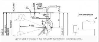
When choosing a fuel level sensor, be sure to take into account the height and geometry of the tank. The length of the measuring element should be slightly greater than the height of the container. If it is less, a small amount of fuel will not be detected by the sensor. The excess part of the fuel level meter can always be cut off. The end of the element should be approximately 3 cm from the bottom of the container. This will allow you to take the most accurate measurements while minimizing the risk of short circuits due to water or debris.
For most vehicles, fuel monitoring devices with a measuring element length of 70 cm are suitable. However, there is a wide selection of meters on the market of different lengths, up to 3 m.
We diagnose and repair the sensor ourselves
If the sensor works, but the level indicator gives under/over readings, first it needs to be adjusted. There are quite reliable ways:
- The float pin moves alternately to its extreme positions. In this case, the arrow on the indicator should also fall into the appropriate positions: 0 for an empty tank and 1 for a full one. If there is no correspondence between the position of the pin and the arrow, the pin itself must be bent and adjustment continued;
- After disassembling the instrument panel, remove the arrow from the instrument and reconnect the wires. You need to start the car, let it run for about 10 minutes, then adjust the indicator axis to position “1” and put the indicator arrow back.
When the sensor often “hangs” at zero, you will again have to disassemble the dashboard, but this time in order to clean all possible places of oxidation. It will also be necessary to check all the masses on the body, in particular the one located under the handbrake.
Get a multimeter. The fuel level indicator has a resistance of about 7 ohms (sometimes a little less) with a full tank, and with a half-filled tank - in the range of 108-128 ohms . When the fuel tank is empty, the resistance fluctuates between 315 and 345 Ohms .
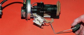
Using a multimeter it is easy to check the sensor itself. You just need to measure its resistance as you add gasoline. If you decide to dismantle the device, you will have to move the float by hand. Note: if changing the float position does not affect the resistance, the sensor is clearly faulty and will need to be replaced.
When several FLS are needed
There are cases when several fuel monitoring devices need to be installed on one vehicle:
- the presence of several fuel tanks. Freight transport usually uses two or even three tanks. In this case, fuel level sensors are installed in all containers, which allows you to get an accurate and complete picture of fuel consumption;
- the tank has an elongated shape (usually installed on car trailers). In this case, minor fuel fluctuations can negatively affect the accuracy of the readings. Therefore, it is advisable to install two (possibly more) sensors in different areas;
- the tank has a complex configuration (installed on agricultural machinery). Installing several devices that measure fuel level will ensure high accuracy of readings.
As for the connection interface, the owner makes the decision himself, based on his needs and financial capabilities.
Replacing the device
If you need to install a new fuel sensor by replacing the old one, then there is no need to go to a service center - you can perform the procedure yourself. You just need to have all the tools at hand.
How to replace the FLS:
- If the car is gasoline, you need to disconnect the negative terminal of the battery at the very beginning.
- Remove the luggage compartment trim and rear seats to gain access to the sensor.
- Remove the protective plate by twisting the screws and thoroughly wipe the surface, removing dirt around the sensor.
- Disconnect all connected electrical circuits, first leaving markings on each to prevent future errors.
- Tighten the screws securing the FLS and carefully disconnect the device. If the meter is installed in the fuel pump, it may need to be disassembled.
- Thoroughly clean the area where the new device will be installed from dirt and glue, ensuring a good seal.
- When installing the sensor, it is important to accurately align it with the gasket and, if necessary, carefully treat the gasket with glue.
- Perform all steps in reverse order, except for installing the trim and rear seats.
Once the connection is complete, diagnostics should be performed. First you need to fill the tank full and make sure that the arrow shows an increase in fuel volume. Then you need to drive at least 30 kilometers and check for leaks and smell of fuel. If everything is in order, then all that remains is to put the seats and trim back in place.
Most actions with the sensor can be done independently. However, you should not disassemble the device and repair it if you do not have experience working with similar devices. It is better to contact the service and get qualified help.