A tachometer is not a necessary element of a car, but at the same time it is very useful. The device significantly extends the life of the engine and eliminates expensive repairs. Anyone who cares about their car should know how to connect a tachometer. This is what we will talk about.
Method of connecting a tachometer to a car.
What kind of device is this
First you need to understand what the device is and what its main functions are. A tachometer is a measuring device that determines the engine speed. The unit of measurement is revolutions per minute (rpm). Almost every modern car is equipped with a device, as it helps to correctly use the engine's capabilities. If the basic package does not include a tachometer, you can buy it separately and install it on both a diesel engine and a gasoline engine.
Testing, tachometer adjustment
If the car is equipped with a distributorless or individual ignition system, the tachometer can be connected to any coil. In this case, the readings of the engine rotation speed (rpm) will be inadequate, since an impulse is supplied to the trammel ignition every stroke, while the individual ignition is four times less likely. However, it is possible to calibrate the measuring scale in a new way.
At the first stage of testing, start the engine and check the performance of the system (arrow deflection at idle speed). As a rule, the speed in this mode is in the range of 800 – 1000 rpm.
Next, adjust the reading level. If the tachometer needle deviates slightly, you can connect an additional capacitor with a capacity of about 1 μF between the signal wire and the vehicle ground. On the contrary, if the arrow goes off scale, connect a variable resistance of about 1 kOhm to the open signal circuit and scale the signal.
The next stage is sea trials. With the engine running, the maximum speed is reached. The tachometer needle should not go into the red zone. Otherwise, the adjustment is carried out again. Before starting operation, check the reliability of connections and insulation again. And remember, additional equipment means new problems.
How the device works
According to the principle of operation, tachometers are divided into magnetic and electric.
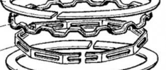
How magnetic models work
Magnetic tachometers operate on the basis of eddy current induction. They occur when a metal disk is placed in a rotating magnetic field. The currents and magnetic field begin to interact with each other, causing the non-magnetic disk to rotate. The tachometer needle is connected to this disk. There is a return spring on its shaft, and the magnet is connected to the crankshaft using a flexible shaft. Increasing the motor speed causes the magnet to move faster, deflecting the non-magnetic disk. This whole process is demonstrated by the arrow.
How electric models work
Such tachometers measure electrical signals and impulses. The ignition system and generator of a gasoline engine generate electrical signals according to the crankshaft speed. Thus, the required signal comes from the electronic control unit.
How to connect a tachometer, test and adjust it?
A tachometer is a device for measuring the rotation speed of engines, shafts, and other mechanisms. The tachometer has been used in transportation technology for more than a hundred years. As a rule, it is installed on the dashboard. The device indicates the rotation speed of the internal combustion engine during operation.
In modern cars equipped with electronic engine control systems, it is not always installed. However, the tachometer readings allow you to select the most suitable driving mode. In some cases, this allows you to save fuel or, conversely, switch to a more aggressive driving style.
Therefore, experienced car enthusiasts and professional drivers often install dashboards with tachometers on their own.
Let's look at how to independently connect a tachometer.
Tachometer
The principle of operation of the tachometer
Currently, tachometers are distinguished:
- Mechanical. A mechanical tachometer receives information about engine speed using a rotating cable mechanically connected to the engine crankshaft. Nowadays such devices are practically no longer used in cars;
- Electromechanical. The operating principle of electromechanical tachometers is based on the conversion of electrical impulses from sensors installed on the engine or from other electronic devices. These signals are converted into magnetic pulses that deflect the needle of the measuring device like a pointer voltmeter;
- Digital. Digital tachometers are used as part of modern computerized panels and are controlled by software and hardware. Self-installation of this type of tachometer is almost impossible.
Types of devices
Tachometers are divided according to the method of displaying information and the connection method. In the first case, there are two types of devices:
- Digital (data is displayed on a small screen);
- Analog (the driver receives information using a moving arrow).
According to the connection principle, tachometers are:
- Regular ones. These are the models that are equipped with modern car brands. They are built into the dashboard.
- Remote. Often such devices serve as a replacement for missing standard tachometers. Their main advantage is that they control idle speed well and have a lower error rate.
Why does the tachometer needle jump?
To find out why the tachometer needle twitches, you need to perform the following manipulations:
1. Find the “Check” lamp on the dashboard and check if it lights up. If not, then, most likely, the system diagnostics will not be able to determine the malfunction.
2. Check the electrical wiring by testing the voltage level on the wiring plus and minus, and also check the condition of the connections.
3. If other equipment or devices are not working correctly, it is imperative to check the weight, because this detail is often overlooked.
4. Check the condition of the distributor contacts and the capacitor on its cover, as it could have been broken during operation.
5. Also, you need to check the circuits in the ignition system.
6. If you have recently repaired or replaced the device, then you simply need to configure it. To do this, you need to adjust the position of the zero and the device itself, adjust the connection quality and make adjustments using the toggle switch on the back of the installation.
7. If the needle jumps when the engine reaches high speeds, the switch is broken and needs to be replaced.
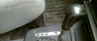
Connection for petrol engine
Now we’ll tell you how to connect an external tachometer. To install the device correctly, you will need a connection diagram for the purchased tachometer, which is included with the device. If there are no instructions included in the kit, then installation will not be difficult for you. Do the following:
- Place the device in a place convenient for you. An appropriate location on the dashboard or its surface is best suited.
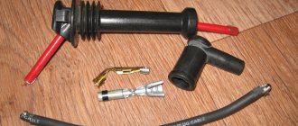
- Understand the wires from the tachometer. There should be 3 of them: black, red and one more wire of any other color, depending on the device model.
- The black wire is connected to the body (body) of the car.
- The red wire connects to the ignition switch terminal, which supplies 12 volts when the ignition system is activated.
- The last wire is connected according to the ignition circuit (contact or non-contact). In the contact circuit, the wire is connected to the distributor breaker, in the contactless version - to the voltage switch.
- Many tachometers have a backlit dial or display. If it is provided for by the technical specifications, then connect the device to the side lights of the car using the corresponding terminal on the ignition switch.
Checking the tachometer functionality
Everything is clear with the installation of the tachometer, thanks to the instructions outlined above. It remains to find out the reasons for the meter malfunctions. Sometimes drivers can observe a situation when the arrow begins to twitch from side to side.
There are several possible reasons for the malfunction:
- When the motor operates for a long time, the resulting vibrations can damage the device;
- faults associated with wiring: tips may become detached, contacts may oxidize, and insulation may be damaged.
These damages can be identified by visual inspection and repaired. If the sensor is faulty, it must be replaced.
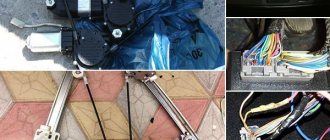
Diesel engine connection
Let's look at how to connect an electronic tachometer to a diesel engine. Installing a tachometer is quite simple.
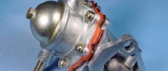
- First, you need a trestle or inspection hole in order to remove the protection from the generator and clean it.
- You will find terminals on the coil that control various processes. You need a terminal marked "W".
Note: if you do not find the terminal you need, use the contact output to the generator rectifier on the winding. Select any of the three contacts and solder it to the end of the device cable. Insulate the connection point.
- We connect the contact from the tachometer to it.
- We close the contact of the oil pump. This is necessary for a more accurate measurement, since otherwise, upon reaching 2500 rpm, a light indicating the oil pressure level will light up on the dashboard.
- We check that the electronic tachometer is connected correctly and reinstall the generator cover.
Important: check that the wires do not come into contact with moving parts.
How to connect a remote tachometer
You will need
- – tachometer of a suitable model
- – a tin can of suitable diameter
- – metal scissors
- - epoxy adhesive
- – polyurethane foam
- – fiberglass
- - dye
- - sandpaper
- – stationery or any other sharp knife
- - awl or chisel
- – putty
- – double-sided automotive tape
- – household hair dryer
- - small rubber spatula
Instructions
Make a body blank. To do this, you will need to insert the tachometer into a tin can of a suitable size, and then evenly and carefully cut off the excess tin using metal scissors.
Try to make the cut smooth, without nicks or burrs, otherwise you will either have to spend a lot of time and effort grinding the edge of the part, or make a new workpiece. Fill the bottom of the can with foam. This will adjust the “fit” of your tachometer in the housing and further strengthen the part.
In addition, apply a layer of polyurethane foam to the outer part of the case in the place where the tachometer is supposed to be attached to the dashboard. Form the future case. After you have allowed the polyurethane foam to dry (it is best to let it sit for twenty-four hours), cut off the excess foam with a knife.
You should have enough space inside to fit the tachometer. The outside of the foam should be trimmed to form a “leg” that we will later glue to the dashboard. Don't forget to also make a hole for the tachometer . The hardest part is behind us. Let's move on to finishing work.
Sand the workpiece. Use sandpaper to smooth out any rough spots on the surface of the foam and to remove the glossy layer of paint from the can.
Strengthen the workpiece body. To do this, you will need to cover the future tachometer with fiberglass, which should then be treated with epoxy glue. In order for the glue to dry completely, the workpiece should be left in a well-ventilated area for twenty-four hours.
Putty the workpiece. The putty will help hide all defects and irregularities and prepare the tachometer for painting.
Paint the tachometer . Give the piece one or two coats of paint to match the color of your dashboard. If necessary, after the paint has completely dried (see the paint manufacturer's instructions), coat the part with one or two layers of varnish.
Install the tachometer. Place the tachometer into the finished housing, lead the wires through the hole you left for them, and connect. If the tachometer works correctly, then its housing must be strengthened on the dashboard. Using a household hair dryer, heat the surface of the dashboard and secure your new tachometer with double-sided automotive tape.
note
Make sure the tachometer is working correctly before mounting it on your dashboard!
Source: https://www.kakprosto.ru/kak-73400-kak-podklyuchit-vynosnoy-tahometr
Tachometer for a two-stroke engine - applications and selection
An electronic tachometer for a two-stroke engine should be considered separately. One of the varieties of such a device is a waterproof version, used in motorcycles, scooters, snowmobiles and other vehicles with two-stroke engines. In practice, this is the same as a tachometer for a single-cylinder engine, which determines its service life, as well as the frequency of maintenance, such as valve adjustment, oil change, spark plugs, etc.
Installing such a device on the mechanism is very simple. There is no need for a separate battery thanks to the built-in rechargeable battery. The connection is made directly to the wire of one of the spark plugs. The resolution of such a device is 0.1 hours, it can count up to a maximum of 10 thousand hours, and then reset.
Tachometer dials vary in size. For example, a device with a diameter of 125 millimeters is most often used in sports cars, where the driver must constantly monitor the operating modes of the engine and especially the amount of its torque. When a certain number of revolutions is reached, a special flash lamp is activated, after which the gear shifts into the next gear. Such large tachometers take up a lot of space and partially block the view.
More convenient devices have slightly smaller dimensions and are already 95 mm. The most common size is 52 mm, which allows you to install the device anywhere on the panel of those cars where their own tachometer is not provided by the design.
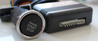
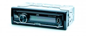
Tachometer with LCD display on microcontroller
There are two options - buy ready-made, or make it yourself. The second way will be within your power if you understand microcontroller technology and know how to program it. In other cases, it is better to purchase a finished product. Again, it should be noted that the VAZ 2101 wiring diagram will be slightly supplemented. First, you need to connect the tachometer to the positive terminal of the ignition switch. VAZ 2107 Replacing the heater radiator! In this video I will show you how to change the heater radiator on a VAZ 2107 car. Secondly, you will need to ensure that the pulses are read. This can be done in two ways:
- Take the signal from the ignition coil.
- Install the proximity sensor on the crankshaft.
The second solution will be more difficult, since you will have to upgrade the crankshaft pulley - you need to make a protrusion on it that will act on the contactless sensor. But taking the signal from the low-voltage output of the coil is a simpler solution.
Circuit diagram of a simple microcontroller tachometer
But you need to remember that during one revolution of the crankshaft exactly two flashes occur in the cylinders. Consequently, two signals will appear on the low-voltage terminal per revolution. This will need to be taken into account when making a tachometer for a VAZ 2101 with your own hands. VAZ 2105, VAZ 2106, VAZ and toe on the VAZ 2101 it is vertical as shown in. How to connect a 220 volt electric motor. In particular, at the stage of programming the microcontroller, this is necessarily taken into account in the algorithm. Which controller to choose is up to you. AtMega128, which has become a classic, will also do an excellent job. You can find a great variety of designs on it.
Another homemade tachometer
In order to measure the number of revolutions, as we already know, counting the pulses of the breaker or the voltage from the spark plugs is used. The frequency of these pulses is linearly related to the motor speed. You can also try to organize an inductive coupling with such a circuit, which will be demonstrated in this device.
For 1500 rpm - 50 Hz. This makes it possible to easily calibrate the device by frequency. Pulses received from the third output of the microcircuit are fed to the dial indicator. In this circuit the author uses a milliammeter. The indicator will show the voltage in this network. Since the duration of the pulses at the output of the microcircuit is approximately the same, the voltage is proportional to the frequency with which sparks are formed.
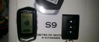
ZenDen › Blog › Instructions for tachometer RL-HM032R for Sea PRO OTH 9.9 S
I bought you know where a tachometer for the PLM. The installation instructions are not complicated... but in the menu everything is not so simple, so I made a translation. Maybe someone will be interested.
Tachometer RL-HM032R PRODUCT USE
Tachometer RL-HM032R
I. Work stroke settings 1. Press MENU six times while the TOT indicator is on and the backlight is off to enter the work stroke control interface. The default setting is 1P1R 2. To enter the clock setting mode, press and hold MENU in the clock control mode until the default setting 1P1R starts flashing. Briefly pressing SET will select the mode. 3. Possible modes
1P1R 1 spark per revolution 6P1R 6 sparks per revolution 2P1R 2 sparks per revolution 3P2R 3 sparks per two revolutions 3P1R 3 sparks per revolution 5P2R 5 sparks per two revolutions 4P1R 4 sparks per revolution 1P2R 1 spark per 2 revolutions
II. Crankshaft rotation update rate (CR) 1. Press MENU seven times while the TOT indicator is on and the backlight is off to enter the crankshaft rotation update rate setting. Default refresh rate is 0.5 sec. 2. To enter the crankshaft rotation update rate mode, press and hold MENU until the original data starts flashing. Briefly pressing SET will select a mode. 3. Refresh rate can be set: 1.0 – update every second 0.5 – update every ½ second
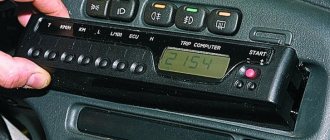
III. Revolutions per minute 1. RPM – shows the current number of revolutions of the CV 2. When the PLM is turned off, the LCD display switches from RPM mode to TOT mode automatically, where the total number of engine hours is displayed.
Waterproof
IV. HF Maximum RPM 1. To view the maximum RPM, press MENU five times while the TOT indicator is on and the backlight is off. The maximum number of HF revolutions since the last launch of the PLM is displayed here. 2. Each time the PLM is turned off and on, the data is updated.
V. Warning about exceeding the permissible number of HF revolutions 1. To set a warning signal about exceeding the permissible number of HF revolutions, press MENU four times with the TOT indicator on and the backlight not working. By default, the overspeed alarm is set at 8500 rpm. 2. To set the maximum RPM number, press and hold MENU in number alert edit mode until the original data starts flashing. Briefly press SET to increase and MENU to decrease the permissible speed indicator. 3. If the set permissible revolutions are exceeded, the RPM and speed indicator will begin to flash. The indication will flash 5 times for 3 seconds, then stop flashing for 3 seconds, and so on cyclically.
VI. Hours display When the PLM is turned off, the LCD display shows the total number of engine hours.
Backlit
VII. Backlight Pressing MENU or SET once turns on the backlight, which turns off automatically.
VIII. PLM operating timer 1. With the backlight off and the TOT indicator on, press MENU twice. The operating time will be displayed. 2. Long press MENU in this mode will reset the timer.
IX. Display of service interval and its settings. 1. With the TOT indicator on and the backlight not working, press MENU three times to enter the SVC service interval setting mode, which counts down. 2. Long press MENU to enter SVC service interval editing mode. The data on the display will begin to flash. To increase, press SET to decrease MENU. 3. By default, the service interval is set to 20 m/h. Possible setting range 0-200 m/h. After setting the required value, the tachymeter will automatically switch to TOT mode, which means confirmation of the successful installation of the service interval. When the PLM reaches the set value, the display will start flashing. 4. To turn off the alert, press SET or MENU. 5. When the notification is turned off, the service interval timer will automatically begin counting down again with the previously specified range before maintenance. 6. If the interval is set to 0H, then the countdown to maintenance is disabled.
X. When the PLM stops and there is no action with the tachymeter for 10 seconds, the LCD display will automatically save all data and go into TOT mode (motor hours mode).
Equipment: Tachometer 1 pc. CR2032 battery 1 pc. Velcro tape for attaching to PLM - 1 set Plastic clamp 2 pcs.
We'll stage it today! I might take a video
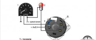
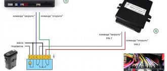
Technical solution
Before connecting the tachometer, it is necessary to draw up an electrical connection diagram in order to mentally determine the starting and ending switching points and trace the conductor. Any ignition coil has a terminal (terminal) +15 (ignition on), to which battery voltage is supplied when the key is turned to the first (for some cars, second) position. Under no circumstances should you connect the tachometer to this point; the first time you turn it on, it may fail. High-voltage wires also pose a danger, even to humans. The signal input to which the tachometer should be connected must be precisely determined. In older coils it is designated by the letter "K", it is better to find the exact circuit diagram of the car.
The next, more difficult task is the electrical connection of the nodes. As a conductor, you should take a stranded copper wire with a cross-section of at least 2 sq. mm. with polyvinyl chloride insulation.
The connection points of the wire to the ignition coil are cleaned, mechanically twisted, soldered and carefully insulated. Lay the wire along any electrical harnesses, using plastic clamps, towards the engine compartment bulkhead near the dashboard. You can insert the conductor into the passenger compartment next to any electrical wiring harness. To do this, it is easier to use an elastic string. Finally, connect the conductor to the tachometer signal terminal. In some cars that include modifications with or without a tachometer, you can simply change the dashboard, find the stock wire and connect it to the ignition coil.
Read also: Soviet files steel grade
Connecting a tachometer with your own hands: pros and cons
The main function of a tachometer in a car is to determine the correct gear, which has a positive effect on the life of the engine. Most cars have an analog tachometer built into them during assembly. The driver looks at the arrow approaching the red line and knows when to shift into a higher gear. Not all cars have the type of device that satisfies the owner, so you just need to figure out what they have and how to connect the tachometer.
- Types of tachometers
- How to connect a tachometer via the ECU
- Connection diagram for a tachometer on a gasoline engine
- How to connect a tachometer to a diesel engine
- How to check the tachometer for functionality
Did you know? The term “tachometer” comes from the Greek
τάχος - speed and μέτρον - measure.
Types of tachometers
There are two types of tachometers: digital and analog. The first looks like a small screen on which the driver can see all the data he needs while driving. The second one is simpler and looks like a board with arrows and values.
Remote
A remote tachometer is installed on the front panel of the car. For greater ease of placement, this device has a leg for mounting on the panel. Remote digital tachometers are good for monitoring idle speed. Their readings have fewer errors, so using such a device you can check the operation of a standard tachometer. In addition, their stylish appearance gives the car elegance.
Staff
The standard tachometer is built into the dashboard of the car. This device is more convenient, since it is easier for the driver to perceive the movement of one arrow, rather than several indicators while driving. A standard tachometer is more often used in cars, and manufacturers of electronic devices produce kits for self-equipping cars.
Important! Measuring instruments are produced according to the car brand. The readings from a non-native mechanism will be incorrect.
How to connect a tachometer via the ECU
If your car does not have a carburetor engine and the injector, the tachometer is not connected to the ignition. In this case, you need to connect the engine control unit to the controller. The connection diagram for the tachometer is simple: take the ground to the body (ground), connect the plus from the device to the ignition positive. The tachometer has two inputs: the first goes to the control unit, the second to the crankshaft position sensor. The device connected to the computer will read pulses directly from the control unit controller.
Connection diagram for a tachometer on a gasoline engine
Before installing a tachometer on a carburetor engine, read the instructions included with the device. If it is not there, install according to the following steps:
- Secure the mechanism in its place (the location is determined by the type of device).
- Connect the black wire to the ground (body) of the car.
- Connect the red wire to the ignition switch terminal, which supplies 12 W during operation of the ignition system.
- The third wire can be any color. Since the ignition system is contact and non-contact, we will consider where to connect the tachometer in both. With a contact system, the device is connected to the distributor breaker. In the second system - to the voltage switch.
If the car has a display backlight, the tachometer is connected to the terminal provided for this in the ignition switch.
How to connect a tachometer to a diesel engine
Before connecting, let’s figure out what makes the tachometer on a diesel engine work. The operating principle of an electronic device is to read pulses sent by a terminal located in the generator.
Since the process is labor-intensive, it must be carried out in an inspection pit.
The first point of work is to dismantle the protective casing of the generator, try to avoid getting dirt. The second step is connecting the tachometer to the diesel generator. To do this, find the terminal marked “W” on the generator body and connect the device output to it.
Attention! It is imperative to close the contact coming from the oil pump. If this is not done, the tachometer may “lie”.
It happens that the terminal indicated above cannot be found. In this case, disassemble the generator. Connect one of the wires connecting the winding and the rectifier to the tachometer cable. Insulate the wires and reassemble the generator in reverse order. Installing a measuring device is not very difficult, but without any knowledge of how a diesel engine works, how a tachometer works on a diesel engine, without the slightest idea about car repair, it is better to turn to professionals.
How to check the tachometer for functionality
We figured out how to connect a tachometer to a diesel and carburetor engine. Now let's look at the reasons for device breakdowns. You notice problems in the operation of the measuring device, for example, an arrow jumping in different directions. There may be several reasons for the breakdown. If the engine runs for a long time, vibration will occur, which may damage the display. The next reason may be oxidation of the contact group of the electrical wiring, damage to its insulation or disconnection from the tips. These are all visible causes that need to be eliminated immediately. If the sensor itself is broken, it needs replacement. If self-diagnosis does not reveal the cause, you should contact a car repair shop.
Malfunction of the tachometer
If signs of a malfunction appear, first you should pay attention to the general condition of the wiring. Very often, damage to the wires or lack of contact in them can cause the tachometer to break down.
Various minor defects in the form of traces of corrosion, minor cracks or loose fastenings are easy to eliminate, but if the damage is serious, the wiring will need to be replaced.
An equally pressing cause of failure is the installation of silicone ignition wires instead of the standard ones. This happens because the linear resistance of silicone wiring is very different from the resistance of factory wires. As a result, the shape of the current pulse changes. If you reduce the value of the resistor on the CP board, the fault will go away on its own.
As for digital tachometers, a popular cause of device malfunction is often the breakdown of a special digital screen that shows the current parameters of the car. To resume operation of the device, you will have to change the LED display.
It is also not necessary to rule out the breakdown of other parts; it is necessary to identify which element is broken and replace it with a new one.