A high-quality color diagram of the electrical equipment of the domestic passenger car VAZ-21074 is provided to help auto electricians and service stations. Model 21074 is an improved modification of the VAZ-2107. The “seventy-four” is equipped with the same 1.6-liter engine, but the carburetor is replaced with an injector. Some elements of the circuit are installed not on all, but only on part of the produced cars of this model. At the end of the article, fuses and the circuits they protect are shown. Schemes are enlarged by clicking.
Electrical equipment VAZ-21074
- 1- block headlights;
- 2- side direction indicators;
- 3- rechargeable battery;
- 4- starter activation relay;
- 5- carburetor electro-pneumatic valve;
- 6- carburetor microswitch;
- 7- generator 37.3701;
- 8- gearmotors for headlight cleaners*;
- 9- fan motor activation sensor;
- 10- electric motor of the engine cooling system fan;
- 11- sound signals;
- 12- ignition distributor;
- 13- spark plugs;
- 14- starter VAZ-21074;
- 15- coolant temperature indicator sensor;
- 16- engine compartment lighting lamp;
- 17- low oil pressure indicator sensor;
- 18- low brake fluid level indicator sensor;
- 19- windshield wiper gearmotor;
- 20- carburetor electro-pneumatic valve control unit;
- 21- ignition coil;
- 22- electric motor of the headlight washer pump*;
- 23- electric motor of the windshield washer pump;
- 24- mounting block;
- 25- windshield wiper relay;
- 26- hazard warning and direction indicator relays;
- 27- brake light switch;
- 28- reversing light switch;
- 29- ignition relay;
- 30- ignition switch;
- 31- three-lever switch;
- 32- alarm switch;
- 33-plug socket for a portable lamp**;
- 34- heater fan switch;
- 35 - additional resistor of the heater electric motor;
- 36 - indicator lamp for turning on the heated rear window;
- 37 - indicator lamp for insufficient brake fluid level;
- 38 - signaling unit;
- 39- heater fan electric motor;
- 40 - glove box lighting lamp;
- 41 - lamp switch on the front door pillars;
- 42- switch for alarm lights of open front doors***;
- 43- alarm lights for open front doors***;
- 44- connecting block;
- 45- cigarette lighter;
- 46- watch VAZ-21074;
- 47- switch for instrument lighting lamps;
- 48- diode for checking the serviceability of the warning lamp for insufficient brake fluid level;
- 49 - fuel level indicator;
- 50 - fuel reserve indicator lamp;
- 51- speedometer;
- 52 - turn signal indicator lamp;
- 53- indicator lamp for closing the carburetor air damper;
- 54 - battery charging indicator lamp;
- 55- carburetor air damper closed warning switch;
- 56 - instrument cluster;
- 57- econometrician;
- 58- courtesy light switches on the rear door pillars;
- 59 - coolant temperature indicator;
- 60 - tachometer 21074;
- 61- parking brake indicator lamp;
- 62 - low oil pressure indicator lamp;
- 63- high beam indicator lamp;
- 64- indicator lamp for turning on external lighting;
- 65-voltmeter;
- 66- parking brake indicator switch;
- 67- switch for external lighting lamps;
- 68- rear window heating element switch with backlight;
- 69- switch for rear fog lights with on/off indicator*;
- 70 - fog light circuit fuse;
- 71- lampshade;
- 72 - rear lights VAZ 21074;
- 73 - level indicator and fuel reserve sensor;
- 74- pads for connecting to the rear window heating element*;
- 75 - license plate lights.
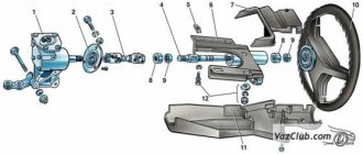
VAZ 21074 engine control system diagram
Wiring diagram of electrical connections of ECM VAZ 21074 - circuit elements. 1 – controller connector; 2 – mass air flow sensor; 3 – coolant temperature sensor; 4 – crankshaft position sensor; 5 – throttle position sensor; 6 – oxygen concentration sensor; 7 – speed sensor; 8 – ignition module; 9 – solenoid valve for purge of the adsorber; 10 – electric fan relay; 11 – electric fuel pump relay; 12 – main relay; 13 – fuse for the power circuit of the electric fuel pump relay: 14 – fuse for the power circuit of the main relay; 15 – fuse link; 16-fuse protecting the constant power supply circuit of the controller; 17 – diode; 18 – idle speed regulator; 19 – nozzles; X1 – diagnostic block; X2 – connection block to the vehicle electrical system.
Trigger malfunctions
But what could happen to this seemingly reliable device? The most common breakdown is that the brushes become unusable. After all, they are in constant contact with the lamellas, and even under the influence of high current. It should be mentioned that if the rotor jams, the current consumption can increase to 600 Amperes! And this is a lot, the wires easily melt, which can lead to a fire. If the brushes are worn out, the rotor will rotate weakly or stop completely. When you turn the key to the extreme position, all the lamps on the dashboard will go out.
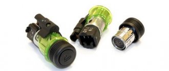
The solenoid relay is the second most common mechanism that fails. Its price is about 400 rubles, but it can do a lot of trouble. Here are a few of its breakdowns:
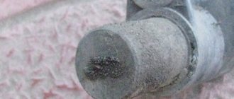
- Melting of the plates or accumulation of carbon deposits on them. The current resistance increases, making starting more difficult.
- There is a break in one of the relay windings.
- Mechanical damage – destruction of housing elements.
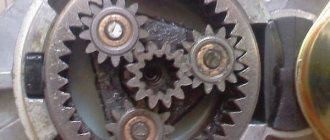
Bendix is a mechanism that consists of an overrunning clutch and a gear. With its help, rotational motion is transmitted from the starter rotor to the crown of the crankshaft flywheel. Most often, the overrunning clutch fails - it should only rotate freely in one direction. When broken, rotation occurs in any direction. And when you try to start the engine, you will hear the starter spinning too quickly. To change the bendix, you will have to almost completely disassemble the starter.
Destruction of windings and lamellas is one of the breakdowns that occurs extremely rarely. It is quite difficult to damage the stator and rotor windings. But a gear starter, for example, along with all its advantages, has a huge drawback - the body is too “delicate”. The engine elements are destroyed, as a result of which the alignment is disrupted and the rotor can hit the stator winding. To prevent this from happening, repairs must be carried out in a timely manner.
Fuse box VAZ-21074 injector
- 1-Rear window heating relay
- 2-Relay for headlight cleaners and washers (if equipped)
- 3-relay or signal jumper (if there is no external relay)
- 4-relay or jumper for cooling fan
- 5-high beam relay
- 6-low beam relay
- F1-F17-Fuses
- 1 (8A) Rear lights (reversing light). Heater electric motor. Warning lamp and rear window heating relay.
- 2 (8A) Electric motors for windshield wiper and washer. Electric motors for headlight cleaners and washers. Windshield wiper relay. Wiper relay and
- headlight washer (contacts).
- 3 (8A) Reserve.
- 4 (8A) Reserve.
- 5 (16A) Rear window heating element and heating relay (contacts)
- 6 (8A) Cigarette lighter. Portable lamp socket. Watch. Front door open warning lamps
- 7 (16A) Sound signals and relay for turning on sound signals. Engine cooling fan electric motor and motor activation relay.
- 8 (8A) Direction indicators in hazard warning mode. Switch and relay-interrupter for direction indicators and hazard warning lights in emergency mode.
- 9 (8A) Generator voltage regulator.
- 10 (8A) Direction indicators in turn indication mode and the corresponding warning lamp. Fan motor activation relay (winding). Control devices. Battery charge indicator lamp. Indicator lamps for fuel reserve, oil pressure, parking brake and brake fluid level. Parking brake warning light relay. Carburetor pneumatic valve control system
- 11 (8A) Rear lights (brake lamps). Body interior lighting lamp.
- 12 (8A) Right headlight. Coil of the relay for turning on the headlight cleaners (with the high beams on)
- 13 (8A) Left headlight. Indicator lamp for turning on the high beam headlights.
- 14 (8A) Left headlight (side light). Right rear light (side light). License plate lights. Engine compartment lamp. Indicator lamp for turning on the side light.
- 15 (8A) Right headlight (side light). Left rear light (side light). Cigarette lighter lamp. Instrument lighting lamps. Glove compartment lamp
- 16 (8A) Right headlight (low beam). Coil of the relay for turning on the headlight cleaners.
- 17 (8A) Left headlight (low beam).
Replacement technology
First of all, you need to disconnect at least one of the wires from the battery, as well as all the wires from the starter. Then you need to unscrew the bottom bolt that secures the starter and screw it in on the reverse side to secure the engine to its front mount. Otherwise, the motor may move forward. After this, you need to unscrew the remaining two bolts that secure the starter and remove it from the car. As mentioned earlier, the bushing is built into the clutch housing. To remove it, you need an M12 tap, as well as a drill chuck. The tap will have to be inserted into the chuck, then clamped, after which it must be carefully screwed into the sleeve, thereby cutting the thread. Great care is required due to the fact that the steel of the tap is very fragile and even a slight misalignment with the applied force can lead to its breakage. In this case, the shank will remain in your hands, and the cutting part will remain inside the sleeve. It would seem that the situation is hopeless. However, it is not. The length of the sleeve is approximately 14 millimeters, which means that there is approximately 10 or 20 mm of the cutting part of the tap on the hands. You need to take a regular nut with exactly the same M12 thread and screw it onto the broken tap. In a situation where the tap is broken off so that it is impossible to screw a nut onto it, you can take a bolt with a corresponding thread about 10 centimeters long and grind grooves on it similar to the grooves of the tap. Or you can do it more radically, but at the same time simpler. Go to the store for a new tap. The tap is equipped with three grooves into which you need to insert nails of the appropriate size. This must be done in such a way that their ends protrude beyond the end of the tap by about 10 mm. Try to insert the resulting structure into the sleeve with the broken end of the tap. It may not work out right away, but with the right amount of persistence the operation can be easily accomplished. After this, you can try to unscrew the piece and try to unscrew the bushing again. As a rule, after a few turns the bushing will begin to rotate and can be carefully unscrewed. If the bushing is very stuck, you will have to cut the thread in it approximately 6 or 8 turns. After this, remove the tap, and in its place screw in a bolt of a suitable size and use it to remove the sleeve. When a new one is inserted in its place, it is slightly pressed in.
Bushings
If the replacement is not happening for the first time, then the bushing can be inserted quite easily by hand. But during long-term operation, this can lead to it turning in the mounting hole. Over time, the mounting hole will break up, forming the so-called eccentricity, and the starter shaft may become misaligned. This means that the starter will stick and the engine will not be able to start. However, this is quite easy to fix. To do this, it is necessary to determine the size of the so-called eccentricity. Then you need to machine or order from a specialist a bushing with a larger outer diameter just to fit the eccentricity. You should solder some solder on the side of this bushing. After this, the bushing will fit in with a slight interference fit.
Electrical diagram VAZ-2107 carburetor
Electrical diagram of VAZ 2107, 21074 produced in 1988-2001 with generator 37.3701
- block headlights
- side direction indicators
- accumulator battery
- starter relay
- carburetor electro-pneumatic valve
- carburetor microswitch
- generator 37.3701
- gearmotors for headlight cleaners *
- Fan motor switch sensor
- engine cooling fan motor
- sound signals
- distributor
- spark plug
- starter
- coolant temperature gauge sensor
- engine compartment lamp
- low oil pressure warning sensor
- low brake fluid level indicator sensor
- windshield wiper motor
- carburetor electro-pneumatic valve control unit
- ignition coil
- headlight washer pump motor *
- windshield washer pump motor
- mounting block
- windshield wiper relay
- hazard warning and direction indicator relay
- brake light switch
- reverse light switch
- ignition relay
- ignition switch
- three lever switch
- hazard switch
- socket for portable lamp**
- heater fan switch
- additional resistor for the electric motor of the heater (stove)
- rear window heating indicator lamp
- low brake fluid level warning lamp
- signaling unit
- heater fan electric motor
- glove compartment lamp
- light switches on the front door pillars
- switches for warning lights of open front doors ***
- front door open warning lights ***
- connection block
- cigarette lighter
- watch
- instrument light switch
- diode for checking the serviceability of the low brake fluid level indicator lamp
- fuel level indicator
- fuel reserve indicator lamp
- speedometer
- turn signal indicator lamp
- carburetor choke indicator lamp
- battery charge indicator lamp
- carburetor choke warning switch
- instrument cluster
- econometrician
- light switches on the rear door pillars
- coolant temperature gauge
- tachometer
- parking brake indicator lamp ("handbrake")
- low oil pressure warning lamp
- high beam indicator lamp
- indicator lamp for turning on external lighting
- voltmeter
- parking brake indicator switch ("handbrake")
- outdoor light switch
- rear window heating switch with backlight
- rear fog light switch with on/off indicator *
- fog light circuit fuse
- lampshade ****
- tail lights
- level indicator and fuel reserve sensor
- connectors for connecting to the rear window heating element *
- license plate lights 2107
Wiring diagram VAZ-2107 carburetor - full view:
In what cases is it necessary to replace bushings?
In the life of any motorist, there may be situations when, for various reasons, it is impossible to start the engine. One of the reasons may be worn bushings. Let's imagine this situation. During starting, the starter with noticeable difficulty tries to turn the crankshaft, every now and then sticking and stopping. At the same time, the uninitiated motorist is perplexed as to why this could be happening, because the battery is in good condition and fully charged. The reason in this case is the armature touching the stator. The gap between the first and second is only tenths of a millimeter, due to this, even the slightest misalignment of the armature shaft relative to the stator will certainly lead to the above problems. This misalignment appears due to the failure of the plain bearings in which the armature rotates. As a rule, the front bearing is more worn out, since the main load falls on it. The bearings in this case are bushings made of brass. The front one is built into a special hole, which is located in the clutch housing. The rear bearing is located on the starter cover.
Bushing replacement
Mounting block connection diagram
P1 — relay for turning on the heated rear window; P2 - relay for turning on the headlight cleaners and washer; P3 - relay for turning on sound signals; P4 - relay for switching on the electric motor of the engine cooling system fan; P5 - headlight high beam relay; P6 - low beam headlight relay; A - the order of conditional numbering of plugs in the mounting block blocks. The outer number with the letter “Ш” in the plug designation is the block number, and the inner number is the conventional number of the plug.
Schemes of individual blocks of the seven
Power supply system
Power plant starting system
1 - starter; 2 - relay; 3 — ignition switch; 4 - battery
Ignition system
1 - generator; 2 — ignition switch; 3 - distributor; 4 - breaker; 5 — candles; 6 - coil; 7 - battery
Contactless ignition system
External and internal lighting
Windshield wipers and washers
1 — electric motors of the windshield wiper; 2 — washer motor; 3 — mounting block; 4 — ignition switch; 5 - washer switch
Cooling Fan
1 — fan electric motor; 2 - sensor; 3 — mounting block; 4 - ignition relay; 5 - ignition switch.
Wires for connecting electrical appliances
| Connection type | Section, mm 2 | Insulation color |
| Negative terminal of the battery - vehicle ground (body, engine) | 16 | Black |
| Starter positive terminal - battery | 16 | Red |
| Positive contact of the generator - plus battery | 6 | Black |
| Generator - black connector | 6 | Black |
| Terminal on the generator “30” – white MB block | 4 | Pink |
| Starter connector “50” – starter relay | 4 | Red |
| Starter Start Relay - Black Connector | 4 | Brown |
| Ignition switch relay - black connector | 4 | Blue |
| Ignition switch output “50” – blue connector | 4 | Red |
| Ignition switch connector “30” – green connector | 4 | Pink |
| Right headlight plug - ground | 2,5 | Black |
| Left headlight plug - blue connector | 2,5 | Green, gray |
| Generator output “15” – yellow connector | 2,5 | Orange |
| Right headlight connector - ground | 2,5 | Black |
| Left headlight connector - white connector | 2,5 | Green |
| Radiator fan - ground | 2,5 | Black |
| Radiator Fan - Red Connector | 2,5 | Blue |
| Ignition switch output “30/1” – ignition switch relay | 2,5 | Brown |
| Ignition switch contact “15” – single-pin connector | 2,5 | Blue |
| Right headlight - black connector | 2,5 | Grey |
| Ignition switch connector “INT” – black connector | 2,5 | Black |
| Six-pin block of the steering column switch - “ground” | 2,5 | Black |
| Two-pin block of the steering column switch - glove box illumination lamp | 1,5 | Black |
| Glove compartment light - cigarette lighter | 1,5 | Black |
| Cigarette lighter - blue block connector | 1,5 | Blue, red |
| Rear window defroster - white connector | 1,5 | Grey |
Diagnosing starter problems
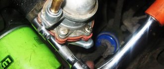
After removal, it is necessary to very carefully clean the starter from any dirt adhering to it to prevent it from penetrating inside the housing. Then we begin diagnostic work. First you need to make sure that the traction relay is working properly, for which we carry out the following actions:
- connect the positive terminal of the battery to the starter output, and the negative terminal to its housing;
- apply a voltage of 50 volts;
- If at the same time the gear of the part (the Bendix, designed to engage with the flywheel and spin it to the required speed) moves out of the housing with a characteristic click, we continue the diagnosis. Otherwise, replace the traction relay.
Car wiring diagram
1 – radiator fan drive motor; 2 – relay and fuse block (mounting block); idle speed sensor; 4 – engine control unit; 5 – potentiometer; 6 – set of spark plugs; 7 – ignition control unit; 8 – electronic crankshaft sensor; 9 – electric fuel pump; 10 – tachometer 2107; 11 – lamp for monitoring the health of electronic systems; 12 – ignition system control relay; 13 – speed sensor; 14 – diagnostic connector; 15 – set of injectors; 16 – adsorber solenoid valve; 17, 18, 19 – fuse block protecting the injection system circuits; 21 – electronic fuel pump control relay; 22 – electronic relay for controlling the intake pipe heating system; 23 – intake pipe heating system; 24 – fuse protecting the heater circuit; 25 – electronic oxygen level sensor; 26 – cooling system temperature control sensor; 27 – electronic air damper sensor; 28 – air temperature sensor; 29 – pressure control sensor.
Fuse and relay diagram 2107
On newer “sevens” a block with 17 fuses and 6 relays is installed. VAZ 2107 fuses on the “new” unit protect the following electrical circuits and devices:
- Reversing lamps, heater fan, rear window defroster warning lamp and relay, rear wiper motor and rear washer pump.
- Electric motor for front wipers.
- Reserve socket.
- Reserve socket.
- Power supply for heated rear window.
- Clock, cigarette lighter, power socket “carrying”.
- Signal and radiator fan.
- Turn signal lamps in emergency mode.
- “Fog lights” and a relay that regulates the voltage of the on-board network.
- Instrument panel lamps.
- Brake light bulbs.
- Right high beam headlight.
- Left high beam headlight, high beam warning lamp.
- Side lights (rear right, front left), license plate and engine compartment lighting.
- Side lights (rear left, front right), glove compartment and cigarette lighter lamps.
- Low beam (right lamp).
- Low beam (left lamp).
The block relays perform the following functions:
- Heated rear window relay.
- Headlight cleaner and washer relay.
- Signal relay.
- Cooling system electric fan relay.
- High beam relay.
- Low beam relay.
The fuse block of the VAZ 2107 (injector) is no different from the block on the carburetor “seven”. Injection models are simply equipped with an additional relay and fuse box installed in the cabin under the glove compartment. The block includes three relays - the “main” relay, the fuel pump relay and the fan relay.
Cleaning nickels from carbon deposits on the solenoid relay
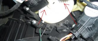
All this is best done on a removed part, which you can read about here. After this, you need to use a deep socket and a wrench to unscrew the three nuts securing the cover to the body, as is clearly shown in the photo below:
When all the nuts are unscrewed, you need to press on all the bolts from the same side and pull them out from the back:
Now carefully fold back the relay cover, but not all the way, as the wire will get in the way:
Pay attention to the central copper plate: it will definitely need to be cleaned of plaque and carbon deposits, if any. Also, you need to unscrew the nickels themselves (two in total) by unscrewing the two nuts on the outside of the cover:
And then you can take them out from there with your hands, from the back side:
Also clean them thoroughly with fine sandpaper until shiny:
After completing this simple procedure, you can put everything back in place in the reverse order. If the problem was precisely the burnt nickels, then it will definitely disappear!
Modifications of the VAZ-2107 car
VAZ-2107 . Basic version of the sedan, with an 8-valve carburetor VAZ-2103 engine, 1.5 liters.
VAZ-2107-20 . The same VAZ-2107, but with a 1.5-liter VAZ-2104 injection engine that meets the Euro-2 environmental standard.
VAZ-2107-71 . The car for the Chinese market was equipped with a VAZ-21034 engine, with a volume of 1.4 liters and a power of 66 horsepower, specially tuned for A-76 gasoline. The pistons were taken from a VAZ-2108.
VAZ-21070 . Modification of a car with an 8-valve, carburetor VAZ-2103 engine, volume 1.5 liters.
VAZ-21072 . Modification with an 8-valve carburetor VAZ-2105 engine, volume 1.3 liters.
VAZ-21073 . An export modification for the European market, which was equipped with a 1.7-liter injection engine with a capacity of 84 horsepower. The engine of this car had a catalytic converter that satisfied environmental protection requirements.
VAZ-21074 . Modification with an 8-valve, carburetor VAZ-2106 engine, volume 1.6 liters.
VAZ-21074-20 . Modification with a 1.6-liter VAZ-21067-10 injection engine, which complies with the Euro-2 environmental standard
VAZ-21074-30 . Like the previous model, but with a VAZ-21067-20 engine, which meets the Euro-3 environmental standard
VAZ-210740 . Modification produced in 2010, equipped with a VAZ-21067 injection engine with a catalyst. Engine capacity is 1.6 liters, power is 72.7 horsepower.
VAZ-21076 . Export modification with a VAZ-2103 carburetor engine.
VAZ-21077 . Export modification with right-hand drive for the UK market. The car was equipped with a VAZ-2105 carburetor engine with a volume of 1.3 liters.
VAZ-21078 . Another export modification for the UK, but with a 1.6-liter VAZ-2106 carburetor engine
VAZ-121079 . The modification, developed specifically for the needs of the Ministry of Internal Affairs and the KGB, was equipped with a powerful VAZ-413 rotary piston engine with a volume of 1.3 liters and a power of 140 horsepower.
VAZ-2107 ZNG . The car is equipped with an 8-valve, fuel-injected VAZ-21213 engine with a volume of 1.7 liters.
Summary
It is worth noting that a starter without a gearbox has a larger gap between the armature and the stator than a geared counterpart. For this reason, its permissible shaft misalignment is also greater.
And one more piece of advice. If the starter is still disassembled, then it would be a good idea to replace the brushes. The parts are cheap, so waiting for them to fail and then dealing with them separately is not worth it. Of course, for all the operations described above, at least a little experience is required. And, as you know, he is a profitable business. In the end, to get it you have to try. Go for it!