______________________________________________________________________________
GAZ-53 engine lubrication system
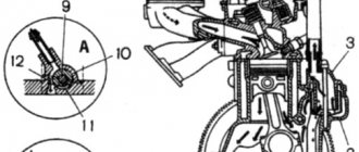
The GAZ-53 engine lubrication system (Fig. 1) is combined: under pressure, splashing and gravity. The oil in the engine oil sump is sucked into the oil pump 9 through the oil receiver 12. From there, oil under pressure is supplied through channels in the block to the full-flow oil filter 4, and from there to the main oil line 6 of the engine. From the main line of the GAZ-53 lubrication system, oil flows through channels in the cylinder block to the main bearings of the crankshaft and camshaft bearings. Through drillings in the crankshaft, oil from the main bearings enters the cavities of the connecting rod journals and through drillings in the connecting rod journals to the connecting rod bearings. In the cavities of the connecting rod journals, the oil undergoes additional purification due to centrifugal forces.
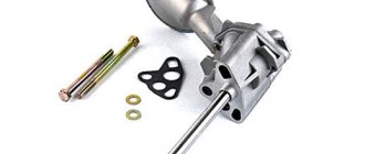
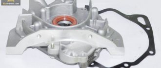
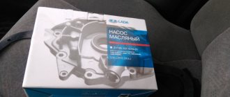
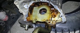
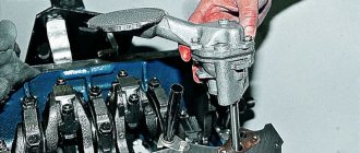
Fig.1. Lubrication system GAZ-53 1 - oil cooler; 2 — cavity of the rocker arm axis; 3 — channel in the cylinder head; 4 — oil filter; 5 — channel in the cylinder block; 6 - main oil line; 7 — hole in the distributor drive housing; 8 - cavity; 9 — oil pump; 10 - pressure reducing valve; 11 - fourth camshaft journal; 12— oil receiver; 13 - safety valve; 14—oil radiator tap, 15—second camshaft journal From the second and fourth camshaft supports, oil flows through channels in the GAZ-53 block and heads to the rocker arm axes. From the internal cavity of the rocker arm axis, oil flows through drillings to the rocker arm bearings. Further along the grooves in the rocker arm bushings, drillings in the rocker arms and adjusting screws - to the upper tips of the rods. Flowing down the rods, the oil reaches the lower tips and flows through the holes in the pushers into the oil sump, lubricating the pusher guides and their ends. The thrust flange of the GAZ-53 camshaft is lubricated through a flat and a hole in the front camshaft support. Drive gears—through a tube from the main oil line. The drive of the ignition distributor, the oil pump and its gears are lubricated with oil coming from cavity 8 located between the fifth camshaft support journal and the plug in the cylinder block. Oil is supplied to other parts that require lubrication by splashing or gravity flow. The oil pressure in the GAZ-53 lubrication system when the vehicle is moving in direct gear at a speed of 55 km/h must be at least 250 kPa with the oil cooler turned off and the engine well warmed up. When starting and warming up a cold engine, oil pressure can reach 500 - 550 kPa. When the oil pressure in the oil line of the GAZ-53 engine drops to 40 - 80 kPa, the emergency oil pressure warning light on the instrument panel lights up. It is permissible for the indicator to light up at a low crankshaft speed in idle mode. If the lubrication system of the GAZ-53 engine is working properly, the indicator goes out when the rotation speed increases. If the indicator lights up at medium and high engine speeds, it indicates a malfunction. Until it is eliminated, further operation of the vehicle is not allowed. When the ambient temperature is above 20 °C and when driving in particularly difficult conditions, it is necessary to turn on the oil cooler by opening the tap located on the left side of the engine. When the radiator is turned on, the faucet handle is directed along the axis of the hose. Oil enters the radiator only when the tap is open through the safety valve. This valve opens at a pressure in the GAZ-53 lubrication system of about 100 kPa. After passing through the radiator, the oil is drained into the oil sump. The oil sump of the GAZ-53 engine is made of sheet steel, stamped, and attached to the lower plane of the cylinder block with studs. The crankcase flange is sealed with a cork gasket. At the bottom of the crankcase there is a drain plug sealed with a metal-asbestos gasket. The oil receiver is mesh, non-floating type. Fig.2. Oil pump GAZ-53 The oil pump GAZ-53 (Fig. 2) is a single-section gear type, driven by the ignition distributor drive through an intermediate shaft. The housing of the GAZ-53 oil pump is made of aluminum alloy, the cover is made of cast iron. The cover contains a pressure relief valve that protects the lubrication system from excessive pressure. The valve is adjusted at the factory and its adjustment during operation is prohibited.
Fig.3. Oil filter GAZ-53 1 - filter housing (upper part); 2 - spring; 3—support washer; 4 - sealing ring; 5 - filter element; 6 — filter housing tube; 7—bypass valve plug; 8— filter housing gasket; 9 — bypass valve gasket; 10—bypass valve spring, 11—bypass valve ball; 12 — oil filter rod; 13 — filter element gasket; 14 — filter housing (lower part); 15 — gasket of the lower part of the filter housing; 16 — filter spacer; 17—washer; 18 — connecting nut; 19 — sealing gasket; 20 — connecting fitting; 21 - sealing gasket; 22 - O-ring Oil filter GAZ-53 (Fig. 3) - full-flow with a replaceable paper filter element Regotmas, consists of the oil filter itself and its spacer. The spacer contains a bypass valve that is activated when the oil filter element is completely clogged. In this case, the oil enters the engine line, bypassing the filter element. The spacer is attached to the inlet pipe with a special fitting and sealed with a paronite gasket and a rubber ring. When the GAZ-53 filter element is clogged, oil flows from the spacer fitting through holes B into the safety valve area, opens the ball valve and, without cleaning, enters the spacer cavity, from where it goes into the oil line. Thus, the bypass valve in the spacer protects the engine from running without lubrication. Fig.4. Drive of the ignition distributor and oil pump GAZ-53 The drive of the ignition distributor and oil pump of the GAZ-53 (Fig. 4) consists of housing 1, into which two bushings made of sheet bronze are pressed. Roller 2 rotates in the bushings, at one end of which there is a slot for the shank of the ignition distributor roller. The slot is offset relative to the axis of the roller, due to which the distributor can be installed in only one position. The drive shaft is secured against axial movements by a retaining ring 7. A spring ring 6 is also installed here. The driven gear 5 is pinned to the lower end of the shaft. The drive gear is located on the camshaft. Two washers are installed between the end of the housing and the driven gear: steel 3 and aluminum 4. At the lower end of the GAZ-53 distributor drive shaft there is a hexagonal hole into which the hexagonal shaft 8 of the oil pump drive fits. This roller is secured with the same pin as the driven gear. The lower end of the hexagonal shaft fits freely into the hexagonal hole in the end of the shaft of the GAZ-53 oil pump. If the oil pump jams for any reason, pin 9 is cut off, and the drive shaft and engine stop. The oil cooler of the GAZ-53 engine is made of a thick-walled aluminum tube, formed into a coil with five straight sections. In straight sections, the oil cooler has special cooling fins made by knurling. The radiator is connected to the engine by rubber hoses. A drop in pressure in the lubrication system can be caused by wear of oil pump parts or crankshaft and camshaft bearings. With significant contributions, the pump begins to operate noisily. To identify pump faults, it is removed from the engine and disassembled. But they begin to disassemble the GAZ-53 oil pump only after checking the condition of the pressure relief valve, since it may cause incorrect pressure in the oil system (the spring is weakened, the plunger is stuck, etc.). The pressure reducing valve is located in the cover of the GAZ-53 oil pump. The force of the pressure reducing valve spring when compressing it to a length of 40 mm should be in the range of 43.5 - 48.5 N. Placing washers under the spring is prohibited. The faulty spring is replaced with a new one. To disassemble the oil pump, unscrew the two fastening nuts and remove the pump from the cylinder block along with the gasket; unscrew the four bolts securing the oil pump cover and remove the cover with the gasket; remove the oil pump driven gear from the housing; remove the pump shaft with drive gear assembly. After disassembling the pump, all its parts are thoroughly washed, dried and inspected. If wear from the gear is found on the surface of the GAZ-53 oil pump cover, then grind the surface of the cover until traces of wear are destroyed. In case of major malfunctions, the pump is replaced with a new one. During repairs, the necessary clearances and tensions in the mating parts must be ensured. When replacing the roller with a new one, as well as during other types of repairs, keep in mind the following: - the distance from the end of the roller with a hexagonal hole to the upper end of the oil pump drive gear should be (42.5+0.15) mm; — a hole with a diameter of 4+0.5 mm, the gear mounting pin on the pump shaft is drilled to a depth of (23±0.5) mm at a distance of 20 mm from the end of the gear. The protrusion of the pin above the plane of the tooth cavity is not allowed; — when pressing the driven gear axis out of the pump housing, the housing is heated to a temperature of 100–120 °C; — to press the axle into the pump casing, the casing is heated to a temperature of 160 - 175 ° C, and the axle is cooled in dry ice to a temperature of - 70 ° C; — when pressing the driven gear axis into the housing, press the axis until it stops (Fig. 6). To assemble the GAZ-53 oil pump, install the roller assembly with the drive gear into the oil pump housing; install the driven gear on the axis in the pump housing; The oil pump cover with a gasket is placed on the housing; secure the cover to the pump body with four bolts. When assembling the oil pump, always change the paronite or cardboard gasket of the cover (their thickness is 0.3 mm). It is unacceptable to use shellac or other sealing agents, or to increase the thickness of the gasket, as this reduces the performance of the pump. Before installing the GAZ-53 oil pump on the engine, it must be filled with oil, since a dry pump at the very beginning of engine operation will not supply oil to the rubbing surfaces, which will lead to their scuffing and failure. When disassembling the GAZ-53 ignition distributor drive, remove the spring ring and remove the safety pin, remove the hexagonal shaft of the oil pump drive, remove the retaining ring and gear from the shaft, remove the thrust washers and remove the shaft from the distributor drive housing. To assemble the ignition distributor drive, before assembly, all drive parts are blown with compressed air and wiped with clean cloths. The shaft assembly is lubricated with clean engine oil, inserted into the distributor drive housing and tested for ease of rotation by hand. Thrust washers are installed on the roller, first steel 3, then aluminum alloy 4. Install the gear on the drive shaft. A hexagonal oil pump drive shaft is inserted into the hexagonal hole at the end of the GAZ-53 distributor drive shaft, a pin is installed in a hole with a diameter of 3.5 mm, a spring ring is installed in the groove on the gear hub, and a retaining ring is installed in the groove of the drive shaft. Check the ease of rotation of the roller by hand, the gap between the thrust washer and the end of the drive gear, which should be 0.15 - 0.40 mm; The displacement of the center of the tooth cavity of the distributor drive gear relative to the axis of the shaft groove is permissible deviation ± 2°.
______________________________________________________________________________
______________________________________________________________________________
- Clutch GAZ-3308, 3309
- Dismantling the GAZ-3308, 3309 gearbox
- Drive axles GAZ-3308
- Transfer case and cardans GAZ-3308
- Cardans GAZ-3307, 3309
- Rear axle GAZ-3309, 3307
- Suspension GAZ-3309
- Steering GAZ-3309
______________________________________________________________________________
______________________________________________________________________________
- Clutch GAZ-53, 3307
- Gearbox GAZ-53, 66
- Rear axle GAZ-53
- Steering GAZ-53, 66
- Ignition installation GAZ-53
- Clutch GAZ-66
- Drive axles GAZ-66
- Brake system GAZ-66
- Winch and power take-off GAZ-66
- Operating systems of the GAZ-66, GAZ-3307 engine
- Engine ZMZ-402 Gazelle GAZ-2705
- Clutch Gazelle GAZ-2705
- Gazelle GAZ-2705 gearbox
- Front axle Gazelle GAZ-2705
- Cylinder head and camshaft Cummins ISF 2.8
- Fuel system of the Gazelle Cummins ISF 2.8 engine
- Cylinder block and piston group of the Cummins ISF 2.8 engine
- Crankshaft engine Cummins ISF 2.8 Gazelle
- Engine Cummins Valdai GAZ-33106
- Clutch and gearbox Valdai
- Bridges Valdai
- Steering Valdai
Catalogs of spare parts and assembly parts
Specifications
Gas 53 weighs 3 tons 250 kg. and has the following parameters:
- from the front bumper to the rear side - 6 m. 40 cm;
- from the left side to the starboard side - 2 m. 38 cm;
- height – 2 m. 22 cm;
- can carry a load of 4 tons;
- clearance from bottom to soil – 26.5 cm;
- the distance between the front and rear wheels is 3.7 meters;
- steel wheel rims;
- the distance between the front wheels is 1 meter 63 cm;
- the tank holds 90 liters of gasoline;
- dry disc clutch, driven by a lever.
The machine has drum brakes with a hydraulic booster.
Characteristics of the Gas 53 engine
Two brands of engines were installed on this car. On later ones, the movers are more powerful. Since 1966, the base vehicle has been equipped with the ZMZ 53 engine, which has the following parameters:
- gasoline, carburetor type;
- six-cylinder, four-stroke;
- engine capacity Gas 53 – 4.25 l.;
- weight – 265 kg;
- A-76 gasoline is used;
- compression ratio – 7.6;
- oil reserve – 10 liters;
- engine power Gas 53 – 115 hp;
Technical characteristics of the ZMZ 53 engine
may vary slightly between models.
The difference is insignificant. The Gas 53 engine brand could only affect cargo transportation and a little on speed. The valves are located at the top. The cylinder block and cylinder head are made of aluminum alloys. Photo of the Gas 53 engine:
Cabin
The cabin is spacious. In addition to the driver, 2 more people can fit. The one-piece seat spans the entire width of the cabin and has a soft backrest. Metal frame of the cabin with two doors - left and right.
Fuel consumption
At 100 km. On the way, approximately 27 to 30 liters of gasoline are consumed, depending on the load.
Advantages and disadvantages
The truck has many positive characteristics. Easy to drive and reliable car. Repairs can be made under any conditions. Spare parts for the car are available. The truck can run up to 400 thousand km. without major repairs. There are also disadvantages. The weak point is the brakes, clutch assembly. They fail more often than other components. Distributor, cardan, shaft - their connection points may fail. In the engine, the main bearing may have a leaking seal.
In the USSR, the most common model of trucks was the GAZ-53 and its modifications. For more than thirty years, since the release of the first car, over 4 million copies rolled off the assembly lines.
The car was produced from 1961 to 1992 at the facilities of the Gorky Automobile Plant.
GAZ-53 engine: technical characteristics
Vehicles of this brand are equipped with several modifications of power units. Since 1966, the GAZ-53 engine was installed on GAZ cars. The model was equipped with a K-126B carburetor and had an overhead valve arrangement. A little later, the characteristics of the GAZ-53 engine changed, since the carburetor was replaced with a K-135.
This engine has a small piston stroke and cylinder volume. Many are of the opinion that parts of other internal combustion engines from the same line can be installed on the GAZ-53 engine. The technical characteristics of these motors are somewhat different, so their elements are not interchangeable. Not only the cylinder blocks are different, but also the cylinder head, piston group and crankshaft.
Engine diagnostics
Regular inspection is necessary for the cylinder block. If its fastenings become loose, tighten the nuts. Before carrying out such work, all the coolant is drained from the system and the fastening of the intake pipe is loosened - this makes it possible to prevent the tightening of one cylinder head from affecting the others.
After such procedures, the nuts are tightened with a torque wrench. The manufacturer recommends performing this type of work for the first three maintenance services, then its frequency can be reduced to every second.
The GAZ-53 engine does not require repairs provided that high quality lubricants and fuel are used. In this case, the carbon deposits formed on the pistons and inside the combustion chamber will be small and will not have any effect on the operation of the engine.
Failure to follow simple rules can lead to detonation, increased consumption and decreased power.
Possible malfunctions of the GAZ-53 internal combustion engine
The power unit has breakdowns and malfunctions that are typical for any other engine. To eliminate them, the GAZ-53 engine is completely disassembled and reassembled. The reasons for breakdowns can be different:
- The appearance of knocking of brass liners. This is the most serious malfunction. It is caused by low oil level, wear of all parts, or reduced or completely absent pressure in the system.
- Increased lubricant consumption. Oil can either flow through the seals and connections, or through the piston rings. This could also be caused by a clogged breather.
- Knocking of connecting rod bushings or pistons. Pistons are characterized by burnout of the bottom or failure of the partitions between the rings. The main reason for this is engine overheating.
- Burnout of exhaust valves. They do not burn out by themselves, but you can often encounter wear on the guide bushings. There may be several reasons for this: ingress of engine oil, low quality fuel, or lack of clearance in the valves.
- Burnout of cylinder block gaskets. The reason is overheating of the engine, which can lead to curvature of the surface of the heads.
