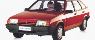
All modern cars are equipped with hazard warning lights, which cannot be said about older cars. For example, in this article we will talk about the legendary Russian “Kopeyka” - VAZ 2101. Since these cars are not equipped with a warning light, car owners have to install it themselves. What is the wiring diagram for the emergency lights on the VAZ 2101 and how to correctly carry out this task - read on.
Purpose and functions of the alarm system
The emergency warning light on the VAZ 2101 is used to notify other road users that the vehicle has made a forced stop due to a malfunction. In accordance with the rules of the road, if a car breaks down, in some cases the driver is obliged not only to turn on the emergency lights, but also to display the appropriate sign. Moreover, it must be placed at a certain distance from the car - this issue is regulated by traffic rules.
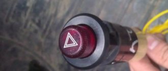
Emergency button on a penny
Replacing the turn relay VAZ 2114
Now it’s time to talk about how to change the turn relay on a VAZ 2114. To carry out all the work you will need: - patience and free hands.
Replacement instructions:
- The first stage is the simplest - open the hood of the car.
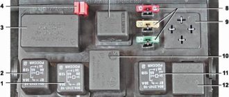
- At the second stage, you need to find the mounting block in which the desired product and fuses are located. Let us remember that the location of the MB is located directly above the right (driver's shock absorber strut).
- To access the contents of the block, we will need to open its plastic protective cover. This can be done by unlatching the two side latches.
- Now you can observe the entire internal structure of the box, however, we are only interested in the product marked K2. Keep in mind that pulling the part out by hand is quite problematic and inconvenient. Especially for such purposes, you can find specialized plastic tweezers in the block, with the help of which it is very convenient to pull out the part and fuses, which we will certainly use.
- To reinstall, take a new product and insert it into the seat so that the three metal contacts are inserted into the socket. After this, press the body of the device and fix it firmly. This completes the replacement of the VAZ 2114 turn signal relay.
Turn signals play an important role in road safety, and their failure can lead to a lot of trouble. A small device - a turn relay - is responsible for the operation of the turn signals. Read about what types of turn relays are used in VAZ cars, how they are designed and work, as well as about their malfunctions and repairs in this article.
Installation and configuration instructions
Installing emergency lights on a VAZ 2101 is not a particularly difficult task; almost anyone can cope with it. To properly connect the emergency lights to a VAZ 2101 with your own hands, you need to prepare everything you may need to complete the task.
Set of tools and materials
So, what you need to prepare before starting the process:
- Locksmith tools, including wrenches, screwdrivers, pliers, etc.
- Insulating tape.
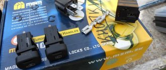
- Four-contact light signal relay from the “Six”.
- Six-pin button for activation.
- Five meters of installation wire (video by Alex Gordon).
Work execution algorithm
So, let's start the process:
- First you need to remove the center console. To do this, you need to unscrew the bolts that secure the trim to the steering column. You will also need to remove the side trims of the windshield pillars.
- Having done this, you can remove the instrument cluster. Be careful not to damage the device.
- Next, disconnect the wires from the light bulb that illuminates the glove compartment. Then unscrew the bolts that secure the sides of the glove compartment to the control panel, as well as the bolts that secure its lower part. After unscrewing all the screws, the glove compartment itself can be removed.
- Now you need to remove the screws that secure the bottom of the dash to the front cross member. Then the nuts of the upper fastening are unscrewed; it is best to reach them through the technological opening of the glove compartment.
- After completing these steps, you can remove the handles from the stove control panel. To do this, at the junction of the lever with the handle, use a screwdriver to bend the lower part of the upper handle, and at the lower handle, you need to bend the upper part.
- Next, you need to disconnect the connectors with wires from the control panel backlight switches, side lights, and also the stove. Then, using a wrench, you need to unscrew two more bolts that secure the fastenings of the stove control levers. After completing these steps, you will be able to dismantle the control panel.
- Now let's move on to installing and connecting the main elements. First, decide on the location of installation of the system power button. It should be installed on the center console so that the driver can reach it as quickly as possible if necessary. It’s still too early to install the button, but you need to decide on the installation location now, since this will determine how much wire you need. Now remove the old turn signal relay from the car and disconnect the three cables from it - usually they are colored black, gray-white and orange.
- Next, take a new six-wheel relay. The second contact of the relay must be connected to the wire that was removed from contact L on the turn signal relay, as well as to output 7 of the button.
- The first contact of the relay must be connected to the fourth contact on the button itself. The third contact is connected to the cable disconnected from contact P on the turn signal relay. Then you need to connect the cable from the fourth contact to ground, that is, the body of the vehicle - it is best to connect it to the relay fixing nut.
- The next step is to connect the button itself. The fourth contact of the button should be connected to the first contact of the relay used. Its second contact must be connected to the cable that was disconnected from the positive contact of the rotary relay. The seventh contact is connected to the second contact of the relay, and the first and third contacts are connected to the steering column turn signal switch; in this case, the order of connection does not matter.
- Now all you have to do is connect the eighth pin to any positive cable; alternatively, you can wedge it into the electrical circuit from the cigarette lighter. If you decide to connect the plus directly to the battery or generator unit, the circuit will need to be protected with a fuse.
- At this point, the installation procedure can be considered complete. All you have to do is securely fix the wiring to prevent chafing of the cables. Reinstall all previously removed interior trim elements, center console, glove compartment, etc.
Design and principle of operation of an electromagnetic-thermal turn relay
Relays of this type do not have a very complicated design. It is based on an electromagnetic relay of a traditional design - a cylindrical core with a winding of thin copper wire. At the top of the core there are two contact groups, and on the sides there are flexible metal anchors (or, as they are called, anchors). One contact group is designed to close the circuit of the turn signal indicator lamp located on the dashboard. And the second contact group directly closes the circuits of the direction indicator lamps, and it is its design features that ensure the blinking of the turn signals.
The armature of the contact group of the turn signal lamps is pulled away from the contact located on the core using a thin nichrome string, so in the normal position the turn signal circuit is open. The opposite end of the string is fixed on a platform made of insulating material, which serves as the basis for installing the core. The nichrome string is connected through a resistor to the turn signal switch circuit, so current flows through it during operation of the relay.
This entire structure is placed in a cylindrical metal case; the bottom of the case is a platform made of insulating material with a relay. At the bottom of the platform there are contacts with the help of which the breaker relay is connected to the turn signal circuit.
The operation of an electromagnetic-thermal relay is quite simple and boils down to the following. When the turn signal is turned on, a circuit is closed that includes the turn signal lamps, a resistor, a relay winding and a nichrome string. Due to the resistance of the resistor, the voltage supplied to the lamps is low, so their filaments burn at full heat. Nichrome, as is known, has a high resistivity and heats up greatly when current flows - thanks to this heating, the nichrome string increases its length, and the armature pulled by it, under the influence of the attraction of the core, straightens and at some point closes the contact group. As a result, current begins to flow bypassing the resistor and the nichrome string, and the turn signal lamps light up in full force.
However, stopping the heating of the string leads to its cooling and shortening, and the armature is again pulled away from the core, opening the contacts - the turn signal lamps go out, and the cycle repeats again. The heating and cooling of the nichrome string occurs quickly, so the lamps blink at a frequency ranging from 60 to 120 times per minute.
The current position of the contact group of the direction indicator lamps (let's call it the first) is associated with the work of the contact group of the signal lamp (let's call it the second). When the contacts of the first group are open, current flows through the winding, but it is not enough to attract the armature of the second group, so the signal lamp does not light up. When the string is pulled and the first contact group is closed, the current flowing through the winding increases sharply, and it is already sufficient to attract the armature of the second contact group. As a result, simultaneously with the blinking of the direction indicators, the warning light on the dashboard also blinks.
Characteristic clicks during operation of the direction indicators occur due to the impact of the anchors on the contacts when they are closed and opened. Clicking is a characteristic feature of electromagnetic relays, and it comes in very handy in breakers.
The electromagnetic-thermal relay has a simple design, and this is its main advantage. But this type of relay has many more disadvantages: over time, the string is stretched, as a result of which the relay stops functioning normally, during operation the relay heats up, which changes its characteristics, and if one of the turn signal lamps burns out, the blinking frequency of the second lamp decreases significantly, and In some cases, the lamp stops lighting up altogether.
Today, electromagnetic-thermal relay-interrupters have been replaced by more modern and advanced electronic relays.
Video “Visual instructions for installing emergency lights”
What nuances should be taken into account when laying wires and installing a button to activate the emergency lights - see the video below (author - LESHA MASTER).
At first I wrote this instruction only in my logbook, but seeing its popularity and the fact that people use it and everything works out for them, I decided to post it here. This is my first article for a wide range of people, please do not judge strictly.
As you know, the emergency warning system began to be installed on cars of the VAZ family starting from the 2104 model, accordingly, it was never on my dime, but the need for this device was obvious: it means flashing an emergency light to the person who let you pass in a traffic jam, and winking at a pretty girl , or simply, almost legally, stop at a public transport stop in front of the bus and run to the kiosk, almost without violating traffic rules, and I’m generally silent about the forced technical stop...
So, for installation we need:
— turn signal and hazard warning relay from VAZ 2106 (four contacts)
- mother block for connecting the relay (2 unnecessary contacts need to be removed).
- hazard warning button from VAZ 2106 (six contacts)
— connector for connecting a button
- wires about 5m of different colors
- electrical tape or heat shrink tubing.
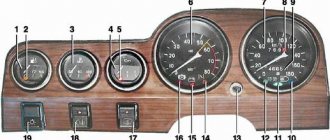
The turn signal breaker circuit for the VAZ 2101 and their modifications is as follows:
1.Front direction indicators 2.Repeaters of direction indicators on the front fenders. 3.Battery 4.Generator. 5. Ignition switch. 6. Fuse block. 7. Relay turn signal breaker. 8.Indicator lamp in the instrument cluster. 9. Steering column turn signal switch. 10. Direction indicators in the rear lights.
Electrical diagram of the rear wiring harness Kalina 2
1, 2 – rear wiring harness blocks to the instrument panel wiring harness blocks; 3 – right side direction indicator; 4 – left side direction indicator; 5 – hand brake sensor; 6 – rear wiring harness block to the tailgate wiring harness contacts; 7 – interior lighting unit; 8 – switch in the driver’s seat belt; 9 – trunk lighting; 10 – electric fuel pump module; 11 – right lamp; 12 – rear wiring harness block to the tailgate wiring harness contacts; 13 – left lamp; 14 – rear wiring harness block to rear left door wiring harness block; 15 – rear wiring harness block to rear right door wiring harness block; 16 – rear wiring harness block to the front right door wiring harness block; 17 – rear wiring harness block to the front left door wiring harness block; 18 – airbag control unit; 19 – rear wiring harness block to the front wiring harness block; 20 – block of the rear wiring harness to the block of the wiring harness of the parking system sensors; 21 – control unit and alarm unit of the safe parking system; 22 – parking system switch; 23 – speaker of the safe parking system; 24 – switch for interior lighting in the driver's door pillar; 25 – interior light switch in the right front door pillar; 26 – switch for the interior lighting in the pillar of the right rear door; 27 – interior light switch in the left rear door pillar; 28 – right seat electric heater switch; 29 – left seat electric heater switch; 30 – electric heater of the right seat; 31 – electric heater of the left seat; 32 – driver’s seat belt pretensioner; 33 – passenger seat belt pretensioner; 34 – central unit of body electronics; 35 – sensor for automatic glass cleaning system (rain sensor); 36 – rain sensor sensitivity regulator; 37 – rear wiring harness block to the instrument panel wiring harness block; 38 – right rear speed sensor; 39 – left rear speed sensor.