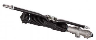
The steering rack is designed to transmit force from the steering wheel to the steered front wheels of the car.
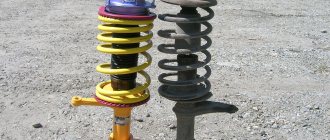
Its design consists of the rack itself, which is a steel strip with notched teeth, a metal body, as well as additional elements in the form of bearings, bushings, seals, anthers, etc.
The rack is driven by the teeth of the steering shaft drive gear, which rotates and moves the rack to the left or right.
Steering rods are attached to the rack, which, in fact, force the wheels to turn in one direction or another.
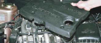
The steering rack is located in the engine compartment at the rear of the engine, and is attached to the lower part of the partition of the engine compartment and passenger compartment.
With the exception of the latest versions equipped with electric power steering, the “dozens” were not equipped with power steering devices.
Replacing the steering rack on a VAZ 2110, VAZ 2111, VAZ 2112
Welcome! The steering rack is responsible for turning the wheels of the car; inside the rack there are mechanisms that make it not so difficult to turn the wheels with the help of the steering wheel, but it is comparable to if you turned the wheels by hand; in addition to the steering rack, the steering rack is also responsible for the easy rotation of the wheels power steering, the power steering can be Electric or Hydraulic, on cars of the tenth family only power steering was practiced, on cars of Ukrainian assembly (Bogdan) an electric power steering was also installed, we should immediately note that removing the steering rack with a hydraulic power steering will be more difficult than without it, you will have to tinker a little, so immediately tune in to this and take into account the fact that a steering rack with power steering costs much more, in addition, when buying a new rack, try to take a new one assembled so that all the tips are there, and so on, if you do this and don’t save a little If you spend a little money, the installation will go much faster and you won’t even have to bother with the rack.
Note! To remove this part, stock up on: Blocks of wood, you will need to put the front part of the car on them and remove both wheels from the front, if you have a pair of jacks, then you can leave the car hanging on them, but it can simply fall off the jacks, all the keys that You also have a large flat-head screwdriver that will come in handy, as well as pliers and a mounting spatula with a hammer!
Summary:
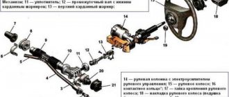
Where is the steering rack located? The rack is located on a shield that separates the engine compartment and the interior of the car, the rack is secured using two metal clamps that secure it on the sides, through a small hole in this shield, the rack goes into the passenger compartment where it connects to the steering shaft, you can understand everything schematically in more detail, You can look at the photo below, in which everything is indicated, but only that very shield (Partition) is not there, and the rail is indicated under the number 18.
When should you change your steering rack? A sign that the rack needs to be replaced is a characteristic knock that will still transfer to the steering wheel, as well as play in the steering wheel, if all these symptoms do not disappear by adjusting the steering rack (How to adjust the rack, read “in this article”), then In this case, the steering rack needs to be replaced.
How to replace the steering rack on a VAZ 2110-VAZ 2112?
Note! Before buying a rack, you should know something, firstly, before you buy a new rack, look at the markings on the old one and buy according to it, racks are generally interchangeable, but to avoid problems, buy everything according to the index and by the way, if If you have power steering installed, then take the new rack from the power steering!
1. Before you start work, unscrew the wheels so that they are pointing towards the front, then hang the front part and remove both front wheels from the car, but before that, carefully secure your car so that it does not fall to the ground, but To do this, you will need to put it on the handbrake, put wheel chocks under the rear wheels just in case, and most importantly, the area on which you are going to do the work must be flat and must be asphalt, in case the car does fall, place the wheels under it in advance ( So that he falls on them).
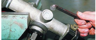
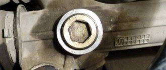
2. Let's go to the salon, while there, you will have to use two keys (one bolt must be kept from turning) to unscrew the nut of the bolt that compresses the clamp clamp, with the help of which the propeller shaft is held on the splines of the steering rack, after the nut is unscrewed, and the bolt is removed (see small photo), insert a powerful screwdriver into the slot (where the bolt was, indicated by a blue arrow) and with its help, unclench the clamp so that the driveshaft can easily come off the steering rack splines.
3. Now, on both sides, pull out the steering tips from the holes into which they go, we will briefly explain how to pull out the tip using the example of the right side, in general, take pliers and use them to pull out the key (This is a kind of metal wire), as soon as it is pulled out, unscrew the nut and using a puller, press the tip out of the hole and that’s it, if you need pictures and you have no idea what a steering tip is, then in this case read the article: “Replacing steering tips”, it says everything in detail.
4. When both steering tips are removed from the holes, proceed to unscrewing the bolts that secure the rods themselves (the steering rods are located on these rods), they are directly screwed to the steering rack in the central part (To remove the bolts, pry up the locking plate with a screwdriver, it is not allows the bolts to unscrew spontaneously) by turning out one bolt at a time, completely remove the rods from the car (you need to pull them out through the wheel arches) and as you already noticed in the small photo, when removing the rod, the person still holds the connecting plate, do not lose this plate when turning out the last bolt , always hold this plate with your other hand.
Note! When the rods are removed, check their silent blocks (These are rubber bands, you will see them immediately, because the rod itself is metal and the rubber part is just silent blocks), their rubber should not be damaged, cracked or have signs of age, otherwise In this case, replace the silent blocks with new ones (see “Replacing silent blocks in rods”) and by the way, worn silent blocks can cause play in the steering, so keep this in mind!
5. And finally, unscrew two nuts on each side that secure the steering rack to the shield, remove the metal clamps and through the arch, remove the rack completely from the car, you can see all this in more detail by looking at the photos below:
Note! This is how absolutely all the racks that were installed on the VAZ 2110 family are removed, while the racks with the power steering are removed in a slightly different way, before starting work you will need to pump out the liquid from the tank with the power steering with a syringe, disconnect the hose from the tank and then put it in any bottle, not when starting the car, turn the steering wheel until all the fluid has drained from the hose, for more detailed instructions on how to remove the rack from the power steering, read the article: “Replacing the steering rack on a Lada Priora” and by the way, when reinstalling it, make sure that the steering rack is installed to the splines according to the marks (For more details about this, read the article: “Replacing the rack on Kalina 1”, point 1) If you need to change the EUR on a Priora? Read - Do-it-yourself electric power steering repair on a Lada Priora.
Additional video clip: Look at the detailed instructions for replacing the rack, it is shown on the example of a VAZ 2109 car, everything is done exactly the same on it, and we will even tell you more, the first generation of the VAZ 2110 was produced with a steering rack from the ninth family, so the differences are There is no removal at all, either on the first car or on the second.
Source
Removal:
1) At the beginning of the operation, you will need to hang both front wheels from the car, for this operation you may need either one or two jacks (Just instead of one jack, you can also use logs), after the front part is hung, remove it from both sides of the car's wheel. (You can find out how to remove a wheel by studying the article entitled: “Replacing wheels on a car”)
Note! Don’t forget to stop the car with the handbrake just in case and put some more bricks under the rear wheels just in case!
2) Now you need to remove the adsorber if you have one, because it takes up quite a lot of space and if you don’t remove it, then there simply won’t be much access to the steering rack. (For information on how to remove the adsorber from a car, read the article: “Replacing a car adsorber”)
3) Then, in the very central part of the rack, unscrew the two bolts that are also indicated in the diagram above as number 10, which secure the tie rods to the rack, but keep in mind the fact that these bolts are also secured with lock washers, which you will need to bend back (You will see them immediately ), so that they do not interfere with unscrewing these bolts securing the rods to the rack.
Note! For ease of unscrewing, you can also move the steering wheel all the way in any direction, because when the steering wheel rotates, the rack also moves, and thus select exactly the moment when it will be easiest for you to unscrew these fastening bolts!
4) Next, climb into the cabin under the place where you have pedals installed and there look for the universal joint locking bolt (Indicated by the red arrow), if necessary, bend back part of the carpet (Carpet is what the floor of the car is covered with, before it didn’t exist, people replace it the styles themselves are linoleum, but this is in old cars, in new ones a carpet is used which covers the metal part of the body) if it will cover this bolt, but when you unscrew the bolt, insert a large screwdriver or a chisel into the groove indicated by the blue arrow and widen it so that the rack can be removed from the car.
5) Well, to complete the operation, unscrew the two (on each side) nuts that secure the rack to the car body, these nuts secure it in its outermost part, that is, on the left and, accordingly, on the right, and when they are unscrewed, then you can pull the steering rack towards you (this will remove it from the studs) and then remove it from the car.
Note! If it is not convenient for you to unscrew the nuts from the engine compartment, then you can, in the side part of it, in the place where you have a telescopic strut installed (the strut spring is indicated by a blue arrow), unscrew all these nuts (one of the nuts is indicated by a red arrow for clarity) securing the rack and then remove it from the car as well! (Pulling out the rack through the engine compartment is not very convenient, so try to pull it out through the cutout where the telescopic stand is installed, you can see this cutout in the photo below)
The telescopic strut spring is shown with a blue arrow and the rack mounting nut is shown with a red arrow.
6) Let’s add something else, usually new racks are initially sold assembled with steering rods, if you also have these rods for the racks (These rods, if you don’t understand what we’re talking about, are shown in the diagram and indicated by numbers 11 and 6) then in this case, you will have to remove the old rods from the car (the instructions are simply aimed at removing only the rack itself, and therefore we didn’t say anything about removing the rods at the beginning), if you don’t know how to remove them, then in this case, study the article entitled: “Replacing steering rods on VAZ 2109 cars.” (Don’t pay much attention to the VAZ 2109 brand, because the cars of the Samara and Samara 2 families are very similar to each other and therefore the rods are removed identically in both)
Installation:
The rack is installed in the same way as it is removed from the car, but only in the reverse order of removal.
Signs of steering rack defects, dozens and pre-repair preparation
A sign indicating problems in the steering mechanism, and most likely in the rack, is a knocking sound in the steering mechanism. It manifests itself when driving on a bumpy road surface, where the road is replete with potholes, holes and bumps from uneven soil or expanding asphalt. This creates a feeling in the car user that this knock is heard directly into the steering column. If such sounds occur in the steering system, it is necessary to diagnose it.
What is the risk of a faulty steering system?
Car steering mechanism
Timely identification of a steering rack malfunction and its repair is the key to safety.
If there is play in the steering mechanism, and there are also constant noises and knocks when driving on uneven roads, then this is a sign that the mechanism requires repair.
Causes of malfunction
The design of the rail itself is relatively simple. During operation, the parts of the mechanism may wear out, so gaps appear between them, which will cause backlash.
Steering design
Anthers also play an important role in the rack, protecting the mechanism from dirt and dust, as well as moisture.
If the rubber boots are damaged or there are leaky places in them, this may cause some problems that may be associated with corrosion or contamination of the assembly elements .
Steering rack diagnostics
If uncharacteristic behavior of the car on the road while driving was noticed, then it is necessary to determine what caused it. There are not many ways to diagnose reiki. They are all simple. Among them are the following:
- a knocking sound is heard in the area where the rack and steering shaft meet when force is applied , then the problem is a lack of bearing lubrication.
- If, by grasping the joint of the rod in the engine compartment, play is detected , this will be evidence of wear on the bushing or insufficient tightening of the connections.
Removing the steering rack bushing
Replacing steering shaft bearings VAZ 2110 1996
1. Disconnect the wire from the “–” terminal of the battery.
2. Remove the steering wheel (see subsection 5.3.1).
3. Loosen the bolt securing the base of the steering column switches and slide the base towards you. 4. Disconnect the wire from the oil pressure sensor. 5. Disconnect the two connectors with the horn wires from the contacts on the base and remove the base of the steering column switches.
6. Insert the key into the ignition switch and turn it to position I to unlock the steering shaft.
7. Disconnect the ignition switch wire block from the wiring harness. If the ignition switch wires are connected to the wiring harness with a clamp, cut or loosen the clamp.
8. The steering column is secured with bolts with break-away heads (the same as the ignition switch). If new bolts with breakaway heads are not available, you can replace them with regular M6 bolts 20 mm long.
9. Unscrew two nuts and two bolts with break-away heads, remove spring and special washers. If the bolt heads are stripped, the bolts must be drilled out or removed using a screwdriver and hammer.
10. Remove the steering column from the studs, slide it towards you and lower it down. Then remove the bolt securing the propeller shaft to the steering shaft.
11. Remove the bolt and remove the column assembly, while removing the thrust bushing from the shaft. 12. Press the steering shaft along with the bearing out of the pipe. It is recommended to press the shaft towards the steering wheel mounting.
13. Remove the front (steering wheel side) bearing from the shaft.
14. Replace the steering shaft if the splines or threads are worn or damaged.
15. Using light hammer blows and a drift, press the rear bearing out of the steering bracket pipe.
16. Before installing the bearings, check that they rotate easily and without jamming. The plastic bearing bushings must not be damaged.
17. Press the rear bearing all the way into the pipe collar using a suitable mandrel, applying force only to the outer race of the bearing. The bearing is mounted on a plastic bushing, which has a wide flange on one side. When installing the bearing, it is the wide flange of the bushing that must be directed outward.
18. Slide the front bearing onto the shaft with the wide flange of the bearing bushing facing the end of the shaft.
19. Insert the shaft into the pipe. In this case, the rear end of the shaft should enter the rear bearing.
20. Press the front bearing all the way into the pipe collar using a suitable mandrel, applying force only to the outer race of the bearing.
21. Install the steering column in the reverse order of removal. Install the thrust bushing on the shaft with the side with the larger diameter.
22. Install special washers for the bracket fastening bolts with their protruding part a in the opposite direction from the bolt head. 23. When installing the base of the steering column switches, before tightening the bolt securing it, adjust the position of the base on the steering column. To do this, install the lower casing and move the base so that the screw holes in the casing and the base match. After this, carefully remove the casing and tighten the base bolt. Install the steering wheel in the reverse order of removal.
Steering parts
1 – inner tie rod ends;
2 – steering gear mounting bracket; 3 – steering gear support; 4 – spacer ring; 5 – steering mechanism; 6 – sealing gasket; 7 – thrust plate of the seal; 8 – seal; 9 – lower flange of the elastic coupling; 10 – intermediate steering shaft; 11 – coupling bolt; 12 – spacer sleeve; 13 – facing casing (upper part); 14 – upper steering shaft; 15 – steering wheel; 16 – signal switch cover; 17 – adjusting sleeve; 18 – steering column position adjustment lever; 19 – retaining ring; 20 – facing casing (lower part); 21 – steering shaft mounting bracket; 22 – steering shaft bearing; 23 – adjusting rod; 24 – outer tie rod end; 25 – spring ring; 26 – protective cover; 27 – sealing ring The steering is safety-resistant, with a height-adjustable (tilt-angle) steering column, and a rack-and-pinion steering mechanism.
The steering mechanism assembly with steering rods is attached in the engine compartment to the front panel of the body on its two brackets using brackets 8 (Fig. Steering mechanism assembly with drive). Fastening is carried out through rubber cushions (supports) with 9 nuts on welded bolts.
In the steering gear housing 17, a drive gear 21 is installed on roller bearings 20 and ball bearings 22, which meshes with rack 16. The inner race of the ball bearing is fixed on the gear shaft with a retaining ring 23, and the outer race is pressed with a nut 26 to the end of the bearing seat in the steering housing mechanism. There is a sealing ring 25 in the recess of the nut. A protective washer 24 is installed between the nut and the locking ring 23.
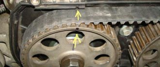
The nut is locked in the crankcase with a washer and covered with boot 28, mounted on the drive gear shaft. Marks A and B are made on the boot and on the steering gear housing to ensure that the steering gear rack is installed in the middle position. The rack 16 is pressed against the teeth of the drive gear by a spring 32 through a metal-ceramic stop 31, which is sealed in the crankcase with a rubber ring 30. The spring is pressed by a nut 33 with a locking ring 34, which creates resistance to unscrewing the nut.
A protective cap 29 is put on the steering gear housing on the left side, and a pipe with a longitudinal groove is pressed onto the right side. The spacer bushings of the rubber-metal hinges 13 of the internal tips 5 and 7 of the steering rods pass through the groove of the pipe and the holes in the protective cover 10. The steering rods are attached to the rack with bolts 6, which pass through the connecting plate 12 and the spacer bushings of the rubber-metal hinges 13. The bolts are secured with a locking plate 11.
The steering shaft consists of an upper 15 (Fig. Steering column) and an intermediate 1 shaft, connected to each other by a cardan joint 4. The intermediate shaft is connected to the drive gear by a flange 9 (Fig. Steering parts) through an elastic coupling. The upper shaft is located in pipe 10 of bracket 3 (see Fig. Steering column) on two ball bearings 13, which have elastic bushings on the inner landing diameter.
Bracket 3 for fastening the steering shaft is attached at four points to the welded bracket 12 of the body, and the front part of the bracket is secured through two fixing plates 11 with bolts with tear-off heads.
The rear part of the steering shaft bracket 3 is secured with welded bolts using nuts with or without spring washers and self-locking nuts.
What is needed to replace the steering rack of a VAZ 2110
To replace the old rack with a new VAZ 2110 we will need: WD-40 fluid, a vice, a puller for removing the tips or a hammer, an open-end wrench “13”, “22”, “19”, a socket wrench with a head “13” , “17”, “22”, chisel and screwdriver, pry bar, jack, new steering rack.
You should pay attention to the fact that the VAZ 2110 power steering steering rack with the article number (21100340001030) costs much more. When buying a new rack, it is more profitable to take the rack assembled so that there are rod ends, etc., and it is better to choose a new part when you have the old one on hand
The price of a standard rack for a VAZ 2110 with article number (21100340001200) will be about 2,500 rubles, and an improved version with power steering costs 15,000 rubles.
The cost of spare parts is indicated for spring 2022 in Moscow and the region.
We repair it ourselves
If you have to repair the rail yourself, it is worth noting that this is a rather complex process that requires a certain skill and knowledge. Of course, DIY repairs will cost less . The work will also require the help of a partner.
Tools and consumables
Required:
- Repair kit.
Steering rack repair kit
- Octahedron.
- Head at "15".
- Jack.
- Mount.
- Head at “10” and “13”.
- Lubrication.
- Parts cleaner.
Dismantling the rack on a VAZ-2112
We have already written in more detail about replacing the steering rack on a VAZ-2112.
First, you will need to remove the battery, the platform under it and the air duct in the engine compartment. Next, you will need to unscrew the clamps that secure the rail to the body. The difficulty of this work is that if you unscrew it carelessly, you can damage the studs , which are quite difficult to replace.
Removing the tie rod ends from the steering rack
After this, you should unscrew the bolts that hold the rod ends. Next, the flange bolt securing the rack is unscrewed. After this, you need to fold the rail away from the body. This will require a pry bar or crowbar. You can pull out the mechanism through the hole in the mudguard. A jack will be needed here.
We carry out repairs
Remember that this unit is a rather “delicate” and fragile mechanism.
under the octagonal nut of the stop there is a spring that needs to be removed;
then remove the retaining ring, which is located under the specified spring;
lightly tap the wooden spacer to tap the rack stop out of the crankcase (note that there is a rubber sealing ring in the groove of the stop);
Next you need to remove the front shield seal;
- under the seal there is a boot, which is also removed (you can use a screwdriver that has a wide and thin blade);
- behind the boot there is a locking ring, which is also removed;
Using a 24mm octagonal head, unscrew the gear bearing mounting nut and remove the nut from the shaft;
we press out the shaft from the gear together with the bearing using a 14mm wrench, which we rest on the mounting blade; the shaft can be clamped in cleats;
- we remove the protrusions of the support sleeve from the holes in the crankcase using a screwdriver;
- •Next we remove the bushing.
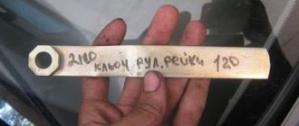
Before installing the new support bushing, install new damping rings on it. This must be done in such a way that their thin part is opposite the cut of the bushing. Next, make sure that the purchased repair kit fits your steering rack (VAZ 2108 or 2110), if it does not fit, then you will have to go and change it, we also recommend getting special keys for repair the steering rack, if it has not been done before.
install a new bushing, before doing this, do not forget to lubricate the area under the bushing;
now you need to cut the rubber rings along the contour of the bushing and remove the cut parts with a special knife;
- the next step is to remove the retaining ring from the gear shaft;
- then you need to press out the ball bearing with a special puller to replace it with a new one;
to press out the needle bearing, we use another puller; if there is none, you will have to cut the bearing with a chisel;
- wash the crankcase cavity;
- install the rail;
but before that we check it for the integrity of the teeth;
we install a new needle bearing (we use cold welding for this; we perform reassembly; it is recommended to install a new protective cover and secure it with clamps (the price of the cover is low); we adjust the rack clearance (it is important to tighten the nut all the way, bending the thread, and then loosen it , turning the key in the opposite direction 30 degrees; do not forget about the lubricant that needs to be filled with the steering rack
That's the whole process, which involves repairing the steering rack of a VAZ 2110 car.
This instruction will help you save significant money and allow beginners to become familiar with the main parts and fastening options for this mechanism.
And it will help experienced car enthusiasts avoid many common mistakes.
Repair
If you decide to repair the steering rack at a service station, expect that you will have to pay about 300 rubles for the simplest repair kit. A complete set, including bearings, will cost about 500-700 rubles. The entire filling, including the rail, will cost 1,500 rubles.
It is advisable to know the markings of the rack before purchasing a repair kit, since they may differ depending on the configuration and year of manufacture of the “tens”.
The cost of repair work, depending on the service station, will be 1000-1500 rubles. If you don’t want to overpay for the work, you can repair the rack yourself.
Work order
- Remove the steering rack assembly.
- Cut the clamps securing the boot (cover) of the steering mechanism.
- Unscrew the thrust nut of the rack (octagonal special wrench 17), remove it from the body.
- Remove the rubber plug from it. Use a screwdriver to remove the retaining ring and spring.
- Lightly tap the steering housing on a wooden block to knock out the rack stop (piston) and remove it along with the seal.
- Remove the boot and drive gear seal (slotted screwdriver).
- Remove the lock washer (slotted screwdriver).
- Unscrew the nut securing the drive gear bearing (octagonal special wrench 24 with a central hole with a diameter of at least 18.5 mm).
- Remove the rack drive gear with bearing from the housing.
- Remove the rack from the housing.
- Pull the support sleeve out of the body by prying it with a slotted screwdriver.
- Remove the retaining ring from the drive gear shaft. Check the bearing for play. If there is one, use a bearing puller to remove the ball bearing from the shaft. Install a new one in its place in the same way.
- Remove the needle bearing from the housing by drilling two holes with a thin drill (2 mm) on the back of the housing and knocking it out using a thin rod. Seal the resulting holes with “cold welding” or “fast steel”. As a last resort, the bearing can be broken using a narrow chisel (not recommended!).
- Liberally lubricate the seat, install a new needle bearing into it, and press it into place by lightly tapping its housing.
- Install a new support sleeve from the repair kit, cut its rubber O-rings, and remove unnecessary fragments.
- Fill the inner surface of the rack body with special lubricant (Fiol-1 or equivalent).
- Insert the rail into the housing.
- Reinstall the drive gear and bearing. Secure it with a nut and install a retaining ring. Place a new boot on the gear shaft.
- Replace the new stop with the new seal. Secure it with a locking ring. Place a spring in its hole. Tighten the thrust nut.
- Adjust the rack by first tightening the stop nut all the way and then loosening it 30 degrees. Plug the nut hole with a rubber plug.
- Place the boot on the rack body and secure it with clamps.
- Install the rebuilt structure on the car.
Cotton steering wheel and how to deal with it
The design of front-wheel drive VAZ cars corresponds both to its price niche and partly to its purpose. An average car for economical travel over average distances at average speed. Know-how of the 80s of the Soviet automobile industry, the MacPherson suspension coupled with rack and pinion looked like something perfect in the early 80s. Although, in fact, the long-travel steering rack 2108 and the classic MacPherson of the 1948 model are not the most progressive solution even for a cheap car.
Compared to classic VAZ models, rear-wheel drive, with a classic steering mechanism and double-wishbone front suspension, the 2110 has more sluggish and imprecise handling. In a word, a wadded steering wheel. It won’t take long to figure out why this happened. Elementary geometry - MacPherson does not hold the car well in turns and during acceleration and braking, and the steering had a long stroke and an unsuccessful upper rack location. Hence the looseness of the steering wheel. It is technically inherent and cannot be cured by any settings or adjustments.
Video tutorial on repairing a VAZ steering rack
However, since the 2000s, a slightly improved design of the power steering rack has been used. There wasn’t enough for everyone at once, because first of all, cars with hydraulic booster were exported. Later, when Europe was full of Zhiguli cars, cars with power steering began to appear more often. But the hydraulic booster did not save the situation. And that's why.
Step-by-step replacement of the steering column
Having decided to replace the steering column on a VAZ-2106 yourself, you need to stock up on free time and patience, and experts recommend performing this step in stages:
- The steering shaft, which is clamped in the column, should be carefully removed.
- Using a size 30 wrench and a long wrench, you should try to rip off the connecting nut that secures the steering column. It is not always possible to remove the fasteners the first time, but since this stage is mandatory, you have to return to it several times.
- The three fasteners that connect the column to the car body are unscrewed. It is most convenient to use a so-called ratchet for this process, since the bolts are not so easy to get to with a regular wrench.
- After unscrewing all the fasteners, you need to free the column from the tie rod splines, which continue to hold the assembly. To do this, you should pry the structure with a pry bar and try to knock it down with sharp jerks.
- After dismantling the unit, it is necessary to check the condition of the boot and oil seal; if even minor damage is detected during a visual inspection, these components must be replaced. By installing a new boot, the life of the bearing and shaft will be extended, and the new oil seal will not allow automotive lubricant to leak out of the steering column.
If all components are installed correctly, the car owner will replace the failed elements with high-quality and reliable ones, and the steering column will have a long service life.
To simplify the assembly process, experts recommend putting all the removed elements from the car in strict sequence, so that when assembling the structure, you don’t confuse anything and repeat the whole process again.
As you can easily see, the process of replacing the steering column of a VAZ-2106 is not that complicated, so every car owner can do it if he has the strength and patience and, of course, does all the work step by step. But if difficulties still arise when replacing a car element, it’s time to use the hint, which at a convenient time can be found in the video instructions on the Internet resource. The educational video lesson is conducted by qualified specialists who understand the intricacies of car repair and present their visitors with extremely effective and most necessary advice on the topic of interest to them.
Checking the oil level in the steering column on a VAZ 2101-VAZ 2107
Welcome! Steering column - thanks to it, both front wheels of a rear-wheel drive car of the “Classic” family are turned. In order for the steering wheel to rotate well and with little effort, the steering column is constantly lubricated with oil located inside it. But like any other oil, the oil inside the steering column disappears over time, and therefore its level must be constantly monitored and topped up whenever possible. You can find out how to check the oil level below.
Note! To check the oil level in the steering column, you will need to take: “8” wrenches, and also, just in case, take with you a funnel, clean oil and a brush or just a rag!
Where is the steering column located? Most likely, you have already seen where the steering column is installed, and more than once, because it is located in almost the most visible place, namely in the engine compartment of the car, on the left side (Indicated by a red arrow), and just above the steering column is the main brake cylinder on the photo indicated by the blue arrow.
How can you tell if there is very little oil in the steering column? Everything is very simple! Usually, when the oil in the columns disappears or there is very little of it, the car’s steering wheel begins to turn heavily, and when you turn the steering wheel, various kinds of sounds and knocks can be heard in the engine compartment of the car, namely the sounds will be made by the steering column itself.
How to check the oil level in the steering column, is it the steering mechanism?
1) First, clean the entire top surface of the steering gear cover from dirt.
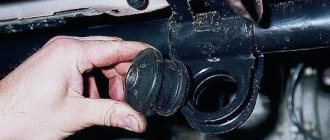
2) Next, unscrew the oil filler bolt indicated by the arrow.
3) And after unscrewing the bolt, check through the hole how much oil is left in the mechanism.
Note! If there is not enough oil, install a funnel and add it! (For information about what kind of oil should be poured into the steering mechanism, see our website “here in this article”)
4) And then screw the oil filler bolt into place.
Important! Avoid getting dirt into the steering gear housing!
Steering column for VAZ 2110 do-it-yourself repair
steering adjustment
We carry out the work on an inspection ditch or a lift.
Using pliers, remove the cotter pin... ...and use a 22mm wrench to unscrew the nut securing the middle link to the pendulum arm. Using a fork puller, we press the middle thrust ball pin out of the hole in the pendulum arm of the Niva 2131. The pin can also be pressed out by applying a sharp blow from below (near the hinge) with a chisel with a blunt end to the pendulum arm. Remove the ball pin from the eye of the pendulum arm.
Similarly, we press the ball pin of the VAZ 2131 rod out of the bipod.
Remove the middle link.
Install the middle link in the reverse order.
The left hinge pin (inserted into the bipod hole), in addition to rotation, can swing (unlike the right one).
At the same time, when installing the VAZ 2121 on a car, we orient it so...
...so that its longitudinal axis is in front of the Niva 2131 hinge axes.
Checking and adjusting the steering of VAZ 2121, Niva 2131
- – Steering gear adjustment
- – Replacement of side rod
- – Removing and installing the middle link
- – Replacement of steering tips
- – Assembling and disassembling the lever bracket
- – Removing and installing the steering wheel
- - Steering column
- – Replacement of the steering mechanism
- – Steering bipod
Steering design of VAZ 2121, VAZ 2131
Features of the Niva 2121 steering device. Adjusting the steering column, eliminating knocks in the Niva 2131 steering mechanism.
DIY steering repair
steering adjustment, inspection and maintenance
NIVA / 2121, 2131 / repair / steering / checking and adjustment / Removing and installing the middle link
How to repair a steering rack
If the steering rack on a VAZ 2112 car breaks down, repairs need to begin with the acquisition of materials, tools and spare parts. Materials:
- Grease for bearings. Preference should be given to Mobil Grease XHP 222.
- Movil in aerosol packaging.
- White Spirit.
- WD-40 can.
- Plastic clamps 200 mm x 4 mm.
- Rags.
- Ratchet socket wrenches.
- Cardan with extension.
- Hammer.
- Puller for removing tips.
- The key is 22.
- Key with internal octagon.
- A chisel, its width is no more than seven millimeters.
- Steering wheel cover.
- Ends with nuts.
- Silent blocks.
- Repair kit for steering rack.
Work order
The instructions indicate that the work is performed on a well-secured vehicle. To do this, chocks are installed under the rear wheels, the handbrake is applied, and the steering wheel is locked.
Tip: To avoid troubles when repairing the steering rack, it is better to disconnect the battery terminals from the car.
- The front wheels are unscrewed.
- Using a special puller, the fingers are pulled out from the lever struts; before doing this, you need to unscrew the nuts of the tips.
- The puller is placed all the way, the screw is tightened. The finger is knocked out of the lever with a hammer, while the key is in a tense state.
- The nuts securing the rack brackets are unscrewed. From inside the cabin, a bolt is removed from the steering shaft.
- Using an oscillating motion, carefully detach the gear shank from the steering shaft. You need to make sure that the splines on the part are not damaged.
- The entire assembly is pulled out through the right hole located in the car body.
- Before starting repairs on a VAZ 2112 car, the steering rack is clamped in a vice. Use a special brush or a cloth soaked in white spirit to clean all surfaces of the assembly.
- The steering rods are pulled out. The bolts on the bracket fixing them are unscrewed, the “tendrils” of the locking plate are bent, using a “22” wrench.
- The locking and connecting rods of the plate are removed.
- The steering rods are removed.
- The retaining ring and support are removed from the right side of the steering gear housing.
- The clamps securing the protective cover are cut off. The parts can be used once and are made of plastic.
- The protective cover is removed.
- The protective cap and support are removed from the left side of the assembly.
- Using a 17mm wrench, the nut on the rack stop is unscrewed, the element is removed, and the spring and retaining ring are pulled out.
The nut, spring and fixing ring are removed from the product
- The rack stop is knocked out of the socket. Carter needs to be hit on a wooden stand. The rubber ring is installed in the groove of the stop for sealing.
- The seal is removed.
- The gear boot is removed; just pry it off with a screwdriver.
- The lock washer is pulled out.
- Using a 24mm wrench, unscrew the nut securing the gear bearing.
- The nut is removed from the shaft.
- Using a “14” wrench, the gear is unscrewed from the crankcase simultaneously with the bearing.
The gear with the bearing is unscrewed from the crankcase
- The rack is pulled out.
- The bushing is removed. The support sleeve is pryed off with a screwdriver, its protrusions should fit into the holes located in the crankcase and then the part can be freely removed.
The support sleeve is removed
- A new bushing is installed. New rubber damping rings are installed on it so that the thin parts of the ring are located against the cuts in the bushing. The protrusions on the bushing should fit freely into the holes on the crankcase.
- The rings are cut along the edges of the bushing and the cut parts are thrown away.
- The fixing ring is removed from the gear shaft.
- Using a two-jaw puller, you need to compress the ball bearing as shown in the photo.
Diagnosis of steering problems dozens
Every car has weaknesses. For VAZ 2110, this is the tie rod end. This part is an integral part of the car's steering system. The tie rods on the tenth generation VAZ end with tie rod ends. Rods are rarely changed, but tie rod ends must be replaced every 40 thousand kilometers of the car.
But this is an average and approximate figure. The service life of the steering tip depends on the driving style of the car owner and the conditions in which the car is operated.
Selection of repair kit
Before starting repair and restoration work, you should decide on the choice of repair kit.
Minimum set. This set includes the necessary list of fastening and sealing elements: washers, bearings, nuts and fluoroplastic bushings.
The basic set has bearings and shafts in addition to the minimum set, but its cost can be twice as high as the first option.
Please note that the steering rack can be either old or new. The old racks are designed for the VAZ 2108, while the new ones are designed for the “tenth” model. The new version is also more convenient to repair. If there is a need to repair the steering rack, which involves replacing the bushing, then there is no need to disassemble the entire mechanism. Remove the corrugation, unscrew the central nut and disassemble the rack into two component parts. One part will contain the mechanism, and the other part will be the one where the bushing is located.
Preparatory activities
The first thing you need to do is buy a steering rack repair kit. Without it, starting work is completely useless. The set may have different configurations.
- Minimum (washers, fasteners, bushings, nuts, bearings).
- Medium (in addition to all of the above, shafts are added). The cost of such a kit is twice as much.
- Maximum (everything is included here, including the rack).
Please note that there are different slats - old and new. The former are intended mostly for the VAZ 2108, and the latter for the VAZ 2110. It is better, of course, to give preference to the second option, because in this case the bushing is much easier to change (there is no need to disassemble the entire rack).
Steering innovations
It seems like the issue has been resolved. Now it was possible to increase the force on the steering wheel, make the number of revolutions from lock to lock minimal, everything was smoothed out by the amplifier, but another problem arose. The car is operated in too different modes and the exact dosage of the steering angle at speeds of 140 and 55 km/h have completely different values. Not to mention the fact that there was almost no effort on the steering wheel, which made the steering even more insane. Then we had to change the design of the steering rack again. This time the objects of attention were the rack/pinion pair. Installing a new pair helped. The new steering rack was called “short” because the number of steering revolutions was reduced from 3.8 to 2.9. As a result, the waviness has almost disappeared and the steering wheel has become sharper.
This was achieved by using an uneven distribution of tooth pitch. In the central position of the steering wheel and at very small angles of rotation, the force on the steering wheel remains noticeable. This is very useful at high speeds. When actively maneuvering, in a parking lot, in heavy traffic and in cramped conditions, the greater the turning angle, the less force on the steering wheel. So the ten began to be controlled more clearly, without losing its lightness. How this affected the maintenance of the rack and its resource is a separate conversation.
Basic faults
Like any other mechanical structure, the steering rack, due to certain circumstances, may show signs of malfunction. These include:
- crunch (knock) when turning the steering wheel;
- “tight” steering wheel;
- increased play in the steering wheel or steering shaft drive gear;
- vibration of the steering shaft when driving;
- uneven tire wear caused by improper alignment of the front wheels.
The listed symptoms indicate that it is time to repair or replace the steering rack. However, do not rush into replacement. The rail itself is made of durable steel, and it is not so easy to damage it. Most often, auxiliary structural elements become unusable:
- support sleeve;
- drive gear bearings (ball and needle);
- seals;
- anthers, etc.
There can be any number of reasons for the failure of these parts, from spent resources to mechanical damage due to off-road driving. If you are sure that the rack itself will not have to be changed, you can get by with minor repairs to the steering structure, which consists of replacing the listed “consumables”.
How does the steering mechanism work?
Steering
injury-proof, with a height-adjustable (tilt-angle) steering column, and a rack-and-pinion steering mechanism.
Steering gear
assembled with steering rods, it is attached in the engine compartment to the front panel of the body on two brackets using brackets 2 (Fig. 1). The mechanism is secured with nuts on welded bolts through rubber pads (supports) 3.
A drive gear is installed in the steering gear housing 5, which meshes with the rack.
The steering shaft consists of an upper 14 and an intermediate 10 shaft, connected to each other by a cardan joint. The intermediate shaft is connected to the drive gear by a flange through an elastic coupling. The upper shaft is installed in the bracket pipe 21 on two ball bearings with elastic bushings on the inner ring.
Fig1. Steering parts: 1 – inner tie rod ends; 2 – steering gear mounting bracket; 3 – steering gear support; 4 – spacer ring; 5 – steering mechanism; 6 – sealing gasket; 7 – thrust plate of the seal; 8 – seal; 9 – lower flange of the elastic coupling; 10 – intermediate steering shaft; 11 – coupling bolt; 12 – spacer sleeve; 13 – facing casing (upper part); 14 – upper steering shaft; 15 – steering wheel; 16 – signal switch cover; 17 – adjusting sleeve; 18 – steering column position adjustment lever; 19 – retaining ring; 20 – facing casing (lower part); 21 – steering shaft mounting bracket; 22 – steering shaft bearing; 23 – adjusting rod; 24 – outer tie rod end; 25 – spring ring; 26 – protective cap; 27 – sealing ring
At each vehicle maintenance check the condition of the protective cover, the protective caps of the 26 linkage joints and the tightness of their fit. They must be replaced if there are cracks, ruptures or other defects that impair their tightness.
Make sure that the steering wheel spoke is horizontal when the vehicle's wheels are straight. Otherwise, determine the cause of the problem and correct it.
Turn the steering wheel from lock to lock and check visually and audibly:
- reliability of fastening of the steering mechanism and steering wheel;
- is there any play in the rubber-metal joints, in the steering rod joints, as well as in the rivet and spline joints of the elastic coupling of the steering shaft;
-reliability of tightening and locking the bolts securing the rods to the rack and the nuts of the ball joint pins;
- are there any jams or obstacles that prevent the steering wheel from turning?
If knocking or binding is detected, disconnect the tie rods from the swing arms of the telescopic suspension struts and recheck. After confirming that the knocking and sticking noise is coming from the steering, remove the steering gear from the vehicle for repair.
The maximum permissible gap between the stop and the nut is 0.2 mm. If necessary, replace worn parts and adjust the gap between the stop and the nut.
What are the possible breakdowns in the VAZ 2112 steering?
Steering elements of a VAZ 2112 car
Main elements of the steering rack:
- 20 – rail.
- 21 – support bushing for the rack.
- 22 – damping ring.
- 23 – rubber-metal hinge.
- 10, 11, 14 – elements for connecting the rack and steering rods.
- 12 – brackets holding the steering mechanism on the shield in front of the body.
- 13 – rubber supports for the steering mechanism.
- 15 – cover to protect the unit.
A drive gear meshes with the steering rack and is mounted in the crankcase on bearings. A stop made of cermet, sealed in the crankcase with a special rubber ring, presses the rack against the gear with a spring. The locking ring prevents the nut from unscrewing. The assembly of the assembly is facilitated by marks located on the boot and the steering mechanism housing.
| Cause of breakdowns | Remedy |
| The free play on the steering wheel has increased | |
| The nuts securing the ball pins of the rods have become loose | The presence of a cotter pin is checked, the nuts are tightened and cotter pinned. |
| The clearance in the ball joints of the rods has increased | The rod ends are changed |
| The rubber-metal joints of the rods are worn out | New rods or rubber-metal joints are installed |
| There is a large gap between the nut and the rack stop | Worn parts are replaced and the steering mechanism is adjusted |
| Noise or knocking noise in the steering wheel | |
| The nuts of the ball joints of the rods are loose | Nuts are checked and tightened |
| There is a large gap between the nut and the rack stop | Worn parts are replaced, the steering mechanism is adjusted |
| The steering mechanism is loose | The nuts are tightened to fix the steering mechanism |
| The fixing bolt on the gear shaft of the lower flange of the elastic coupling has become loose | The bolt holding the lower flange of the coupling is tightened |
| Steering wheel turns hard | |
| Damaged upper suspension strut bearing | Replace the support assembly or bearing |
| Defective support sleeve or rack stop | New parts are installed, lubricant is added |
| The tire pressure on the front wheels has decreased | Normal pressure is established |
| Malfunctions in the parts of the ball joints of the rods | Damaged parts are replaced |
| Damage to elements of the telescopic suspension strut | Repairing or installing a new suspension strut |
| Damaged bearings on the upper steering column shaft | Bearings are changed |
| The column is not fixed in the desired position | |
| The adjustment lever pinch bolt turns | The lever with the adjusting sleeve is unscrewed from the bolt and the protrusion of the bolt is installed in the slot of the guide plate on the steering shaft bracket |
| The adjustment lever rests on the facing casing | The facing casing, lock washer, and lever are removed. The sleeve is tightened, the lever is put on in the desired position. The reliability of fixation and operability of the tensioning device is checked, the lock washer and the facing casing are installed |
Steering column
| 1 – sound signal panel; 2 – steering wheel; 3 – eccentric; 4 – spring; 5 – headlight switch; 6 – windshield wiper/washer switch; 7 – switch casing; 8 – bearing; | 9 – lower casing of the steering column; 10 – steering column shaft; 11 – centralizing plastic disk; 12 – steering column; 13 – steering column lock drum; 14 – lock drum; 15 – lock casing; 16 – safety plugs; 17 – upper casing of the steering column |
Sectional view of the ignition switch housing
Source