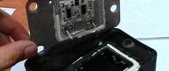
The ignition module is a mechanism whose malfunctions are very difficult to identify. Usually, problems begin to be solved when it becomes obvious that something is wrong with the car. If your VAZ 2107 does not start the first time, you cannot set the ignition, and uneven engine operation begins to confuse you - it’s time to carry out a proper check. Let us recall that the engine ignition module of the “injector” type is the same system that, with the help of coils, supplies electrical energy in order to form a spark and start the car.
Egnition lock
Removing the “seven” lock
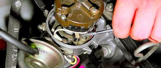
The ignition system on the domestic seven includes two main components - a coil and a module. The lock, in turn, consists of several parts - the switching mechanism itself, as well as the contact circuit. Each of these components is independent in its design, so if one of them breaks, it can be replaced without completely changing the lock. As for repairs, the VAZ 2107 ignition module can be repaired at home if you have all the necessary tools and an idea of how this procedure is performed.
On a carburetor or injector, the functionality of the lock can be determined using a special tester - a multimeter. To check contact ignition, the multimeter probes should be connected to the outputs on the lock one by one, and the output should correspond to one or another position of the key. If the contact group is operational, the multimeter will display a resistance that tends to zero. If the resulting indicator is different, this indicates the need to repair the contact group or replace it. In some cases, such parameters may be due to oxidation or burnt contacts, which can be corrected without replacing the group.
Signs of breakdown
When the ignition is turned on, the engine ECU malfunction indicator light comes on, and after the engine is started, it should go out. A burning warning light is the first sign of problems with the ignition system. Other prerequisites for diagnosing the ignition module are “floating” engine speed and problems with starting. The cause of such failures may be faulty high-voltage wires or spark plugs, so you need to make sure they are working before you start diagnosing the ignition of the VAZ 2107 (injector). Often, cylinder misfires occur due to compression problems or damage to the intake manifold gasket. This must be taken into account when searching for the causes of engine failure.
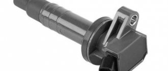
Ignition coil
Black short circuit for the "seven"
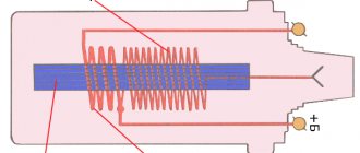
Any type of ignition, including dual-circuit ignition on a VAZ 2107, cannot work normally without a coil. The main task of this component is to convert low voltage to high voltage. It is the high voltage in the ignition system that will make it possible to break through the air gap between the spark plug and produce the spark necessary to ignite the combustible mixture in the cylinders. To ensure normal ignition performance of an injector equipped with nozzles or a carburetor, a B117A coil is used on the contact system.
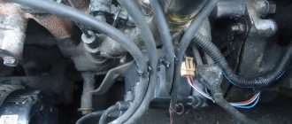
As for the location, the VAZ ignition coil is located in the engine compartment on the left mudguard. It is fixed with two special pins. As for the device itself, it is a regular transformer with a magnetic core. This element consists of an external magnetic conductor, as well as a core, and is equipped with two windings.
The cylindrical body of the device itself is made of durable steel, which protects it from damage. The entire structure is closed from above using a sealed lid made of a special insulating material (the author of the video about the adjustment is the channel Behind the Steel Gates).
Carburetor
There are a large number of strobe lights on the market, but in general their operating principle is equally suitable for ignition installations. The price only affects the service life of this device. The strobe light operates while the engine is idling. The ignition is adjusted by aligning the marks on the crankshaft pulley with the scale on the timing cover. The matching of signs is assessed using a stroboscopic light beam.
When using a VAZ 2107 with 92 or 95 gasoline, the average mark of the scale should coincide with the pulley mark. In case of deviation, the ignition angle must be adjusted by turning the distributor housing. When turning the distributor clockwise, the advance angle increases, and when moving in the opposite direction, it decreases.
Display Guide
So, we figured out where the VAZ module and ignition coil are located and what functions they perform, now let’s talk about setting them up. If the system torque is set incorrectly, this will cause increased gasoline consumption, as well as detonation of the power unit (the “fingers” will start knocking). In general, the operation of the motor will be unstable.
To set up the ignition of a VAZ 2107, you need to perform several steps, all of them are described in detail below:
- First, you need to correctly adjust the gap that exists between the interrupter device. To do this, you should dismantle its cover in advance and clean the contact surface. At the same stage, it is necessary to check the connection of the contacts - the elements must come into contact over the entire surface, and not just in certain areas. If the contacts are poorly connected, you should try to bend them slightly. You can also try sharpening the plane a little.
- Having done this, we move on to an important stage. You need to turn the crankshaft until the contacts open as much as possible. Using a feeler gauge, you need to increase the gap to approximately 0.45 mm. It should be noted that during this, the probe between the contacts should move with low resistance.
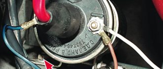
- The crankshaft rotates until the “ignition timing” mark marked on the pulley itself. Having done this, a voltmeter should be connected to the terminal of the interrupting mechanism; if it is not there, a regular test light can be used. We are talking directly about the breaker terminal, which is connected to the coil. Using a 13mm wrench, you need to slightly loosen the nut securing the breaker to the BC.
- After these steps, you need to turn the key in the lock, but do not start the engine; at the same time, the breaker body must be turned counterclockwise. When you notice that the light has gone out, you need to start turning the housing in a different direction until the light comes on again. If the control light is on, this indicates that the moment of spark transmission through the high-voltage wires has been set. Once the torque has been established, the breaker fixing nut should be tightened until it stops.
As for checking, this is easy to do. When the car is traveling at a speed of 40 km/h, you need to press the gas so that the vehicle quickly gains power. During rapid acceleration, a brief detonation should occur until the car can accelerate to 60 km/h. If this is so, then the moment was set correctly and for some time you can forget about this procedure.
Sorry, there are no surveys available at this time.
Adjusting the gap of the VAZ 2107 distributor breaker
The quality of the spark depends on the distance between the switch contacts and the condition of the contacts themselves. To adjust the VAZ 2107 distributor, you need to do the following:
- tighten the fixing screw;
- loosen the screw securing the switch contacts;
- disconnect the mounting brackets and remove the distributor cap;
- unscrew the screws securing the slider;
- install and secure the slider;
- Clean the switch contacts with sandpaper (to avoid damaging the contacts, you must use sandpaper with a grit size of no more than 600).
- turn the adjusting screw to set the gap to 0.4mm using a suitable thickness gauge;
- secure the dispenser lid.
- remove cursor;
In addition to adjustment, repair of the VAZ 2107 distributor may be required. This consists of cleaning the contacts on the distributor cover or replacing the cover itself, replacing the slider, resistor or contact group.
US Postal Service » May 15, 2009, 01:31 pm
During the overhaul of the internal combustion engine, the chain with stars was changed. The timing belt was set according to marks: respectively on the crankshaft pulley, tooth and sprocket of the timing chain. But there was such garbage - put a mark on the bottom - you definitely won’t put the one at the top - it comes out a little to the right or to the left, but if you throw it over the tooth, it turns out to be quite good. How is this actually done correctly?
At first I thought that the ignition timing was definitely set on the computer - I went to the service station for diagnostics - they told me that the computer was supposedly flashed and they couldn’t configure anything using the tag - maybe Zizdat or they don’t know each other? As far as I remember, on the 409 engine it was controlled by the ECU
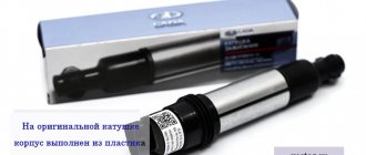
Diagnostics and replacement of the ignition coil on the seven
The ignition of the air-fuel mixture in the cylinders is carried out by a spark plug, which requires a high voltage of about 11-20 kV to operate. The current conversion in the ignition system of the VAZ2107 car occurs in a special cylindrical transformer. This device is installed in the engine compartment on the mudguard on the left side and is attached to it with two studs.
The type of coil used on the VAZ2107 is B-117A, it was specially designed for classic cars with a contact ignition system. This device consists of the following parts:
- core;
- external magnetic circuit;
- primary and secondary winding.
The core is a set of plates made of steel of special electrical grades. This part is the basis for coils isolated from each other. The coil has a metal body filled with transformer oil. The cover, made of dielectric, has two contacts for powering the primary coil and one terminal for the high-voltage wire.
Wire selection
Many people face a problem when replacing wires, and it’s hard to say which company to choose, which one is better, but new wires are always better than old ones, so you need to evaluate your capabilities strictly by the thickness of your pocket. The price range for high-voltage wires is quite large.
The most popular brands of high-voltage wires are SLON, AvtoVAZ, TESLA, these brands have proven themselves well and are in good demand.
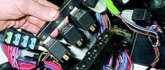
PROCEDURE FOR CHECKING IGNITION SYSTEM DEVICES
The main reason for the failure of this device is a wire break in the primary or secondary winding. This ignition system device is checked using a multimeter set to resistance measurement mode. The operation can be performed either directly on the car or after it has been dismantled.
Open the hood of the VAZ2107 car and disconnect the battery. The coil installed on the mudguard in the engine compartment is disconnected from the on-board network and cleaned of contaminants. At the first stage, we check the resistance in the primary winding; its value should be in the range from 3.0 to 3.5 Ohms. We perform the same operation for the secondary winding, acceptable values are from 7.4 to 9.2 kOhm.
Connection diagram for high voltage wires
Connecting new or removed old wires must be done strictly according to a specific scheme. Otherwise, the spark will not coincide with the compression stroke in the cylinder block.
In other words, when the fuel mixture is ready to ignite in the cylinder, a spark is required to ignite it. If the connection is incorrect, the spark will not appear at the required moment and ignition will not occur, which will make starting the engine impossible.
Scheme
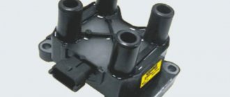
The order and counting of cylinders in VAZ engines starts from the timing belt drive, from left to right, that is, the first cylinder will be at the timing belt, and the 4th at the oil filler neck.
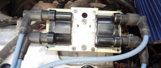
Most often, the cylinder number is indicated on the ignition module, but there are cases when there are no designations on the module, then it is necessary to connect the cylinders according to the diagram shown below.
- The first cylinder is connected to the lower left contact on the MH;
- The second cylinder is connected to the upper left contact on the MH;
- The third cylinder is connected to the upper right contact on the MH;
- The fourth cylinder is connected to the lower right contact on the MH;
REPLACING THE DEVICE
If the indicators do not correspond to the above values, the ignition coil is considered faulty. Such a device must be replaced with a working one, which can be purchased at almost any spare parts store. When purchasing the device, you must inspect it and check the availability of documents: technical passport and certificate.
Removing the ignition coil on a VAZ2107 car is carried out with the battery disconnected. Use a wrench to unscrew the nuts on the contact and mounting studs. The faulty device is removed. A spare part is installed in its place and secured and connected. Now you can connect the battery and start the engine.
Sources
- 7vaz.ru/remont/diagnostika-i-zamena-katushki-zazhiganiya.html
- autocentrum.ru/brands/lada/17209-obzor-sistemy-zazhiganiya-vaz-2107-katushki-i-drugih-elementov-posobie-po-vystavleniyu.html
- drive2.ru/l/487397562748240344/
- 21074.ru/elektrooborudovanie/kak-proverit-modul-zazhiganija-vaz-2107-inzhektor-multimetrom/
- bumper.guru/klassicheskie-modeli-vaz/elektrooborudovanie/zazhiganie/zazhiganie-2107/katushka-zazhiganiya-vaz-2107.html
Contactless distributor
In "sevens" with a contactless ignition system, a distributor of type 38.3706 is used. As already mentioned, the design of a non-contact distributor is similar to a contact one, with the exception of the mechanism responsible for creating electrical impulses in the low-voltage circuit of the system. Here, instead of a contact group, this function is performed by a Hall sensor. As for the malfunctions of the non-contact distributor, they are the same as those of the contact distributor, therefore, it is not advisable to consider them again. But it’s worth talking about the sensor in detail.
A Hall sensor is installed in the contactless distributor instead of a contact group
Hall Sensor
The operation of the sensor is based on the phenomenon of induction. The design of the device is based on a permanent magnet and a hollow cylindrical screen with four cutouts in the form of a crown. The screen is fixedly fixed on the distributor shaft. As the shaft rotates, the protrusions and cutouts of the “crown” pass through the groove of the magnet. This alternation causes a change in the magnetic field. Signals from the sensor are sent to a switch, which converts them into electrical impulses.
The operation of the sensor is based on the phenomenon of inductance
If the Hall sensor fails, the engine may not start at all, or it starts with difficulty and runs intermittently. The sensor cannot be repaired, but you can check its functionality yourself.
Hall sensor check
There are several ways to diagnose a sensor. The simplest of them involves replacing the device being tested with a known good one. The second method is to measure the voltage at the sensor terminals using a voltmeter. Measurements are taken at terminals 2 and 3 of the device. The voltage between them should be 0.4–11 V. If there is no voltage or it does not correspond to the specified parameters, the sensor must be replaced.
The voltage between pins 2 and 3 should be 0.4–11 V
You can check the device's functionality by simulating its operation. To do this, you need to disconnect the central high-voltage wire from the distributor cover, insert a working spark plug into it and place it so that the “skirt” touches the “ground” of the car. Next, you need to disconnect the sensor connector from the distributor, turn on the ignition and connect terminals 2 and 3 to each other. If a spark appears on the spark plug during a short circuit, the sensor is working, otherwise the device must be replaced.
Hall sensor replacement
To replace the sensor, you will need to remove the distributor from the engine. The order of further work is as follows:
- Remove the cover by unfastening the latches.
- We dismantle the slider.
- Using a drift and pliers, remove the shaft coupling mounting pin.
- We remove the shaft from the housing.
- Disconnect the vacuum corrector rod.
- Using a flathead screwdriver, unscrew the two screws that secure the sensor.
The sensor is secured with two screws - Remove the Hall sensor.
Once the screws are unscrewed, the sensor can be easily removed - We install a new part in its place.
- We assemble and install the distributor in the reverse order.