Almost all electrical devices on these cars are designed for 12 volts. In this case, the amperage can vary from hundreds of amperes to tens of milliamps. To separate power and control currents, a switching relay is used. This prevents the wires from getting too hot or catching fire. At the same time, it reduces the overall amount of wiring in the car. Location of switches in the car:
- On the left under the dashboard is block 1 under the first set of fuses. Here are the relays for the Niva 21214 fuel pump, ignition, main switch and both electric fans.
- To the right of the steering column, the relay block is responsible for the fog lights, heated rear window of the trunk door and both types of light (two elements for high and low beam).
- Above the second block are the hazard warning and turn signal relays.
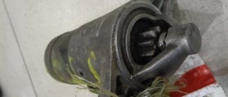
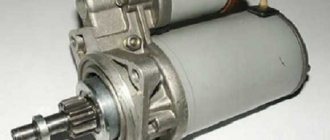
- The starter relay on Niva 21214 is designed for several hundred amperes and is installed in the engine compartment.
It is important to maintain the normal condition of electrical circuits and replace their elements with original ones. Otherwise, complete failure of the controlled unit and a complete stop of the vehicle are possible.
Examination
Read
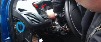
In order to check whether the traction relay , you must first get to the starter. It is located under the hood, in a standard place for VAZs - on the left below the battery, near the gearbox.
The starter itself and the retractor are located in one housing, which also has two terminals. When dismantling or reinstalling the device, you should be extremely careful not to short-circuit these terminals.
You need to check the voltage limit that the traction relay . The limit voltage is no more than 8V. In addition, the temperature during the actuation process should not be higher than 25°C, otherwise you will not get reliable operation and protection of the starter.
In addition, you can sometimes visually notice a breakdown. In this case, it is necessary to install a new mechanism, but first you need to disassemble it.
Lada 4×4 3D › Logbook › Extras. Niva starter relay
Hello friends! I wrote about my problem with starting the car earlier, the essence is simple: you turn the key, and in response there are only clicks. I didn’t know what it was, the car had this problem since it was purchased in November 2015. Since then, there have been no hypotheses, no matter what has not changed (explosive wires, starter retractor, switch), in addition, all the places where the minus is attached to the body have been cleaned. Nothing helped. We thought and wondered, consulted for a long time - what to do? I asked a question here, they gave me different advice, and so my friend and I decided to install an additional relay on the starter. Maybe it will help! And let me tell you, it helped! To solve the problem, we bought: a 4-pin 30A relay, “mothers, fathers”, 1.5 wire (taken with a reserve), heat shrink. We prepared and assembled everything according to the diagram, all that remains is installation.
Full size did everything as advised
Full size when all the wires have been prepared, all that remains is to connect according to the diagram
Full size opened the main circuit, connected it to the relay, again according to the diagram
Full size of the relay itself secured together with the switch
The full size was made according to this scheme - everything works! It took about 15 minutes to prepare the wires, then we connect according to the diagram and try - everything works! Starts with half a turn! After installing additional relay no matter how much I tried to turn the ignition key, the car always responded as it should! Problem solved, now it's just history!
Bye everyone! ————- Update dated August 9, 2022. During 2 weeks of operation, there were 2 cases when this circuit failed. The day was hot, I drove for a long time (fields and forests, i.e. under good load), the engine compartment got hot like hell, and after I turned off the engine, it did not restart. The relay was cracking and the starter was not spinning. I had to hook it up according to the old scheme (actually connecting the old wires), the car started. Then, as soon as everything cooled under the hood, I connected it according to the new circuit, and everything started up. My mistake is that the relay overheated to the limit. It may be something else, but when everything cooled down under the hood, the new circuit worked flawlessly. ———— Update from 08.20.17. The relay finally cracked. Connecting according to the old scheme works, but, as before, it is bad. In the end, I just bought a new relay, installed it and forgot about the problem. Now everything works.
Fuse box in Niva Chevrolet
Every car has an electrical circuit that powers all the electrical devices in it. The Chevrolet Niva is no exception; it is full of electronics.
From time to time, this electronics malfunctions and needs to be corrected. The first thing you should pay attention to in case of such failures is the fuse box, as well as the relay.
This article will discuss the Niva Chevrolet fuse box with a description.
If one or another device in the car fails, then first of all you should pay attention to the protective fuse block, since they are the ones who protect all devices from factors such as increased current and short circuits. Therefore, you need to know where they are.
Read news about the new Niva
- Purpose of fuses, relays and their replacement Niva VAZ 21213, 21214, 2131 lada 4×4
- Diagram and location of the fuse box Niva VAZ-21213 and 21214
- Diagram and location of the fuse box Niva VAZ-21213 and 21214
- Solenoid relay NIVA 21213; 21214 KZATE 57.3708-800-04; 2110-3708805 (gear starter) 6013 – Electrics and Light
- Where is the fuel pump fuse for Niva Chevrolet?
- About engines for VAZ 2121 Niva
- Front lower suspension arms VAZ-2121 - Drawings, 3D Models, Projects, Cars and automotive industry (Car service)
- Timing marks on a Chevrolet Niva car
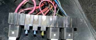
Engine Control Relay Box
It is located under the main fuse box and consists of 5 relays and 1 fuse.
Scheme
Electrical diagram of the block
Decoding
- Ignition relay
- Main relay
- Right cooling fan relay
- Left cooling fan relay
- Fuel pump relay
- Fuel pump fuse F5 15A
The only difference between Nivas with injection and carburetor systems is due to the fact that the engine control relay unit can be located under the hood of the car in a specially designated compartment.
Mounting blocks for Lada 4×4 2018
The main and additional units are located in the cabin to the left of the steering wheel under the dashboard. The blocks contain cylinder, ten and six fuses, respectively. Fuse ratings and assignments are shown in Table 4, Fused Circuit:
Standard size fuse box. The device is located on the left under the upholstery and contains fuses designed to protect engine control system devices. Fuse ratings and designations are shown in Table 5:
The fuse and relay box is located on the left side of the steering column under the instrument panel. The device contains two “Standard” type fuses, which are designed to protect electric fan circuits, electric windows and electric mirrors. Fuse ratings and designations are shown in Table 6:
The fuse and relay box is located on the right side of the steering column under the instrument panel. The unit contains one Maxi size fuse and two standard size fuses that are designed to protect the ABS hydraulic circuits. The ratings and assignments of fuses are shown in Table 7:
Attention!
The relay and fuse layout may vary depending on the equipment and date of manufacture of the vehicle. The current circuit diagrams of the mounting block are given in the operating manual for the date of vehicle release (download from the site for 3d or 5dv.).
Why is the fuse or light relay constantly on or any other? Before replacing it with a similar one, you must first find and eliminate the cause of its burnout. It could be a short circuit, incorrect current rating, etc. Use the wiring diagrams to troubleshoot. Questions on this topic can be asked on the forum.
General arrangement of blocks
Scheme
Description
- Engine control system fuse box
- Windshield wiper relay
- Main fuse box
- Engine Control Relay Box
- Additional relay block (above the gas pedal, and not shown in the diagram)
Malfunctions
After removal, you need to carefully check the solenoid relay . Here is a list of possible breakdowns:
- The nuts that secure the wire ends have become loose/loosened. Easily solved by tightening the nuts;
- Wires, windings, connections have oxidized. This may require replacement or just cleaning;
- There are breaks in the power supply circuit. Treatment - chain replacement;
- The anchor operates untimely or runs idle. Replacement ordered;
- You also need to check if there is a short circuit between the turns of the windings (there are two of them).
An ohmmeter is used for checking.
Additional relay block
This block is located above the gas pedal.
Scheme
Description
- Rear fog lamp relay
- Rear window heating relay
- Low beam relay
- High beam relay
A little higher, above the block, a relay can be installed - a breaker for the turn signals and hazard warning lights.
Separate fuses and relays can be installed under the hood: on cars with ABS, on the left side of the engine compartment near the ABS hydraulic unit, a block with fuses is additionally installed that protect the elements of the anti-lock brake system and the starter relay not far from the starter itself.
Mounting blocks for Lada 4×4 2022
The main and additional units are located in the cabin to the left of the steering wheel, under the instrument panel. The blocks contain fuses of the “Cylinder” size, ten and six fuses, respectively. The ratings and purpose of the fuses are indicated in Table 4 “Circuits protected by fuses”:
Fuse block of standard size “Standard”. The block is located on the left side under the upholstery and contains fuses that are designed to protect engine control system devices. The ratings and purpose of the fuses are shown in Table 5:
The fuse and relay box is located on the left side of the steering column under the instrument panel. The block contains two “Standard” size fuses, which are designed to protect the circuits of the electric fuel pump, electric windows and electric mirrors. The ratings and purpose of the fuses are shown in Table 6:
The fuse and relay box is located on the right side of the steering column under the instrument panel. The block contains one “Maxi” size fuse and two “Standard” size fuses, which are designed to protect the circuits of the hydraulic unit of the anti-lock braking system. The ratings and purpose of the fuses are shown in Table 7:
Attention!
The relay and fuse diagram may differ depending on the configuration and production date of the vehicle. Current diagrams of the mounting block are presented in the operating manual for the date of manufacture of the car (download from the official website for 3-door or 5-door).
Why does a fuse or light relay or any other constantly blow out? Before replacing it with a similar one, you must first find and eliminate the cause of its burnout. This could be a short circuit, incorrectly selected rated current, etc. Use electrical circuit diagrams to troubleshoot problems. Questions on this topic can be asked on the forum.
Knowing the electrical wiring system on your car will save you the cost of visiting a car service center. The electrical circuit on Nivas is quite simple, like all cars. Replacing damaged elements is intuitive and does not require serious knowledge.
Design and operation
Read
The starter on the VAZ 2110 is designed in such a way that it contains a traction relay , which ensures the rotational movement of the drive gear. It starts when it engages the teeth of the crankshaft flywheel. That is, if the retractor device is faulty, then the engine will not start.
In addition, it is the traction winding that, when the contacts are closed, is designed to provide power to the starter motor from the battery. When the contacts close, the interlocks are activated and the pull-in winding is turned off.
The solenoid relay directly from the ignition switch and also serves to protect the starter. But since it consumes a lot of current, over time reliable contact disappears in the contact group.
Useful video
Due to the fact that the switches are of the same type, during emergency repairs the output circuit can be connected to other units. To do this, you will have to disable one of the auxiliary and non-critically important elements. For example, transfer the starter or healing circuit to the rear window heating controller.
Relays and fuses VAZ 21214, 21314 (Niva 4x4 injector)
Modern AvtoVAZ SUVs use injection power units. In the event of a malfunction in the vehicle's electrical equipment, first check the serviceability of the fuses and relays. We will then show where the mounting block (fuse box or black box) is located, as well as the location of the elements inside it.
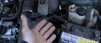
Removal
Dismantling and disassembly is carried out as follows:
- Disconnect the negative voltage from the battery;
- Remove the air filter;
- Disconnect the block of wires going to the traction relay ;
- Unscrew the nut securing the tip of the power drive (wrench 13);
- Unscrew the nuts securing the starter (key 15). The top nut twists easily, but the bottom one still needs to be approached;
- Remove the starter ;
- Unscrew the nut from the lower terminal of the traction relay and disconnect the wires;
- Unscrew its mounting bolts (key 8) and remove.