Turn relay VAZ 2101 connection diagram.
The turning pattern of the VAZ 2101 is based on the electromagnetic-thermal RS57. The principle of connecting the VAZ 2101 turn relay is quite simple and applied to all cars that were produced in those years. The VAZ 2101 electromagnetic-thermal turn relay, type RS57, consists of a core with a winding, a panel, two armatures, a nichrome string, a resistance and two pairs of contacts. The left armature with a pair of contacts opens and closes the circuit of signal lamps, and the right armature with its contacts ensures the operation of the indicator lamp.
Windshield wiper connection diagram
1 – generator; 2 – battery; 3 – ignition switch; 4 – windshield wiper switch; 5 – windshield wiper relay; 6 – windshield wiper gearmotor; 7 – thermobimetallic fuse; 8 – windshield wiper switch located in the windshield washer pump; 9 – fuse block; A – the order of conditional numbering of the plugs in the relay blocks and the wiper gear motor
Turn relay VAZ 2101 operating principle.
When the turn switch is turned on, the current from the battery passes through the resistance and the nichrome string of the VAZ 2101 turn relay to the indicator lamps. In this case, the string is heated, which, as a result of thermal expansion, lengthens, reducing the gap in the contacts, but since the circuit resistance is high, the signal lamps will not light. Closing the contacts leads to the removal of the resistance and nichrome string from the circuit, the resistance decreases, and the signal lamps light up.
At the same time, the passing current in the core winding increases, which leads to the formation of an electromagnetic field, which attracts an additional right armature, closing its pair of contacts and turning on the test lamp. Since no current passes through the string, it cools down and takes on its original length, opening the contacts. The signal lamps go out, the current in the armature winding decreases, and the contacts of the signal lamp open. The frequency of switching on and off the alarm arms of such a relay is 60 – 120 times per minute. The disadvantage of the VAZ 2101 turn signal relay is the presence of a nichrome string, which heats up during operation, which leads to heating of the relay itself. In addition, when the relay operates for a long time, the string is stretched and the relay becomes unusable. The use of such a relay as an alarm relay is also not possible, since due to the passage of a large current and a long operating time, the relay will heat up even more, which can lead to a fire. Also, the passage of a large current through the nichrome string will cause it to quickly stretch and burn out, which will lead to rapid failure of the relay.
Car diagram - Zhiguli 2101
Let's look at the electrical circuit diagram for the VAZ 2101 1970-1985. Somewhere in the early 70s, the founder of the future VAZ classic, the Zhiguli VAZ-2101, was born, making a revolution in the Soviet automotive industry. This small car, an analogue of the Fiat 124, had good comfort for those times, excellent handling and stability, as well as a very dynamic engine, so “kopecks,” as our compatriots lovingly “christened” them according to the last digits of the index -01, gained enormous popularity. Today, most of this rarity has served its useful life or is in poor technical condition. Although there are still well-maintained examples that have been repeatedly “reanimated” and continue to patiently travel along the roads of the CIS countries.
External lighting switching diagram
2 – engine compartment lamp; 3 – battery; 4 – generator; 5 – reverse light switch; 6 – fuse block; 7 – indicator lamp for external lighting in the instrument cluster; 8 – glove box lighting lamp; 9 – instrument cluster lighting lamp; 10 – plug socket for a portable lamp; 11 – instrument lighting switch; 12 – external lighting switch; 13 – brake light switch; 14 – ignition switch; 15 – lamp switches located in the front door pillars; 16 – lamp switches located in the rear door pillars; 17 – lampshades; 18 – trunk lighting lamp; 19 – rear lights; 20 – license plate light; 21 – reversing lamp
Turning on the headlights - diagram
1 – headlights; 2 – battery; 3 – generator; 4 – fuse block; 5 – headlight switch; 6 – external lighting switch; 7 – ignition switch; 8 – indicator lamp for high beam headlights in the instrument cluster
Diagram for switching on direction indicators for Zhiguli 2101
1 – sidelights; 2 – side direction indicators; 3 – battery; 4 – generator; 5 – ignition switch; 6 – fuse block; 7 – relay-interrupter of direction indicators; 8 – indicator lamp for direction indicators; 9 – direction indicator switch; 10 – rear lights
Turning on sound signals - diagram for VAZ 2101
1 – sound signals; 2 – battery; 3 – fuse block; 4 – sound signal switch; 5 – generator
Windshield wiper connection diagram
1 – generator; 2 – battery; 3 – ignition switch; 4 – windshield wiper switch; 5 – windshield wiper relay; 6 – windshield wiper gearmotor; 7 – thermobimetallic fuse; 8 – windshield wiper switch located in the windshield washer pump; 9 – fuse block; A – the order of conditional numbering of the plugs in the relay blocks and the wiper gear motor
Wiring diagram for the electric motor of the heater fan on the Zhiguli 2101
1 – generator; 2 – battery; 3 – ignition switch; 4 – fuse block; 5 – heater switch; 6 – additional resistor; 7 – heater fan electric motor
Electrical circuit diagram for VAZ-21011, VAZ-21013 cars
1 – headlights; 2 – front direction indicators; 3 – side direction indicators; 4 – battery; 5 – battery charge warning lamp relay; 6 – relay for turning on low beam headlights; 7 – relay for turning on the high beam headlights; 8 – generator; 9 – starter; 10 – engine compartment lamp; 11 – spark plugs; 12 – oil pressure warning lamp sensor; 13 – coolant temperature indicator sensor; 14 – sound signals; 15 – ignition distributor; 16 – windshield wiper gear motor; 17 – brake fluid level warning lamp sensor; 18 – ignition coil; 19 – electric motor for windshield washer; 20 – voltage regulator; 21 – heater electric motor; 22 – glove box lighting lamp; 23 – additional resistor of the heater electric motor; 24 – plug socket for a portable lamp; 25 – parking brake warning lamp switch; 26 – brake signal switch; 27 – relay-interrupter of direction indicators; 28 – reverse light switch; 29 – fuse block; 30 – relay-interrupter for the parking brake warning lamp; 31 – windshield wiper relay; 32 – heater motor switch; 33 – cigarette lighter; 34 – lamp switches located in the rear door pillars; 35 – lamp switches located in the front door pillars; 36 – lampshades; 37 – ignition switch; 38 – instrument cluster; 39 – coolant temperature indicator; 40 – control lamp for high beam headlights; 41 – indicator lamp for external lighting; 42 – turn signal indicator lamp; 43 – battery charge indicator lamp; 44 – oil pressure warning lamp; 45 – control lamp for parking brake and brake fluid level; 46 – fuel level indicator; 47 – fuel reserve warning lamp; 48 – instrument cluster lighting lamp; 49 – headlight switch; 50 – direction indicator switch; 51 – sound signal switch; 52 – windshield washer switch; 53 – wiper switch; 54 – external lighting switch; 55 – instrument lighting switch; 56 – sensor for level indicator and fuel reserve; 57 – trunk lighting lamp; 58 – rear lights; 59 – license plate light; 60 – reversing light
Electrical diagram of the equipment of the VAZ-2101, VAZ-2102 car
1 – headlights; 2 – sidelights; 3 – side direction indicators; 4 – battery; 5 – battery charge warning lamp relay; 6 – generator; 7 – starter; 8 – engine compartment lamp; 9 – spark plugs; 10 – oil pressure warning lamp sensor; 11 – coolant temperature indicator sensor; 12 – sound signals; 13 – ignition distributor; 14 – windshield wiper motor; 15 – brake fluid level warning lamp sensor; 16 – ignition coil; 17 – voltage regulator; 18 – windshield wiper switch located in the windshield washer pump; 19 – heater electric motor; 20 – glove box lighting lamp; 21 – additional resistor of the heater electric motor; 22 – plug socket for a portable lamp; 23 – parking brake warning lamp switch; 24 – brake signal switch; 25 – relay-interrupter of direction indicators; 26 – reverse light switch; 27 – fuse block; 28 – relay-breaker for the parking brake warning lamp; 29 – windshield wiper relay; 30 – heater electric motor switch; 31 – cigarette lighter; 32 – lamp switches located in the rear door pillars; 33 – lamp switches located in the front door pillars; 34 – lampshades; 35 – ignition switch; 36 – instrument cluster; 37 – coolant temperature indicator; 38 – control lamp for high beam headlights; 39 – indicator lamp for external lighting; 40 – turn signal indicator lamp; 41 – battery charge indicator lamp; 42 – oil pressure warning lamp; 43 – control lamp for parking brake and brake fluid level; 44 – fuel level indicator; 45 – fuel reserve warning lamp; 46 – instrument cluster lighting lamp; 47 – horn switch; 48 – headlight switch; 49 – direction indicator switch; 50 – external lighting switch; 51 – instrument lighting switch; 52 – wiper switch; 53 – sensor for level indicator and fuel reserve; 54 – trunk lighting lamp; 55 – rear lights; 56 – license plate light; 57 – reversing lamp; 58 – plug blocks of the rear bundle of wires of the VAZ-2102 car; 59 – lampshade for illuminating the rear part of the VAZ-2102 car
Turning relay VAZ 2101 replacement with an electronic relay.
If desired, you can replace the electromagnetic-thermal relays of the VAZ 2101 with an electronic relay used on VAZs of subsequent brands. The connection is made in almost the same way. In addition to the standard wires, it is necessary to add only one wire connecting the electronic relay to the vehicle ground. In this case, you can also connect an alarm button.
Modification of the PC-57 turn relay | Cheerful Pencil
Technical evolution, technological progress - all this is good and wonderful. But when you have reliable, albeit old, equipment in your hands, equipped with the simplest electrical equipment, it does not calm you down for long. The reliability of the same equipment drops significantly if its production itself is treated as a handicraft and carelessly.
The old T-40 tractor is minimally equipped and few people do not know this. You can install any electrical equipment on it, creating comfort in operation and providing full detail of the operation of the engine and the unit as a whole. Is this just for everyone?
Yes. It was possible to install any electronic breaker relay or contact-transistor turn relay from modern technology, but any type of electronics had to be abandoned. Owner's wish. Everything is minimal and simple.
We settled on one of the 1984 PC57s. The principle of its operation is very simple, but this simple work was not performed by this relay. I will dwell on this very briefly.
In order for the relay to operate immediately after voltage is applied to it, and for the operating periods to be the same, it is necessary that an electromagnetic field be present in the relay core with a force sufficient to reliably hold the moving armatures with commutating contacts to the yoke of the core.
The magnetic field in the relay coil is also present at those moments when its switching contacts are open, but it is so weak that it is not enough to attract the armatures to the core. In our case, the electromagnetic field was weak even when the contacts of the control pair were closed with a lowering resistance shunt.
The magnetic field of a coil depends both on the amount of current flowing through it and on the number of turns forming the coil itself.
Typically, for light signaling of direction indicators, two 21 W incandescent lamps are required, not counting repeater lamps. The control lamp does not count, since it operates from a different contact group of the relay and is not connected to the relay coil.
In our problematic case, the PC57 relay taken for installation refused to work even when connecting four 21 W lamps (4X21) and two 55 W lamps (2X55), not to mention the control lamp. But how will it work if the number of turns of the core coil is less than the calculated one? So we had to add the same number of turns of wire to the existing coil. Simple and accessible.
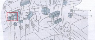
Underhood wiring
The electrical circuit of the iconic car is distinguished by its simple layout and reliable operation. The wires are connected to the corresponding sensors, devices and components. Connection tightness is ensured by convenient quick-release plug connections.
The entire electrical wiring system can be divided into six bundles of wires:
- front;
- rear;
- right and left;
- clusters of headlights and side turn indicators;
- battery cables;
- instrument panel wires.
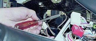
A complete replacement of the engine compartment wiring is necessary if there are numerous twists in the old cables
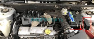
Under-hood wiring includes the front bundle of wires, wires for the turn signals and battery. The main sensors and instruments are located in the engine compartment:
- battery;
- starter;
- generator;
- ignition module;
- high-voltage wires and spark plugs.
Neatly laid wires under the hood speak of the driver’s love for the car.
The thickest wires connecting the car body with the battery and engine serve as the power source for these devices. These wires carry the greatest current when the engine starts. To protect electrical connections from water and dirt, the wires are equipped with rubber tips. To avoid scattering and confusion, all wires are collected into bundles and divided into separate bundles, which are easier to replace if necessary.
Complete replacement of the braid will eliminate loss of tension due to poor contact and numerous twists
The harness is wrapped with adhesive tape and secured to the housing, which prevents individual wires from hanging freely and being caught by moving parts of the power unit. At the location of a specific device or sensor, the harness is divided into independent threads. The harnesses provide a certain order for connecting devices, which is reflected in the electrical diagram.
A detailed diagram allows you to find a section of wires with poor contact
Position numbers of electrical circuit elements on the VAZ 2101 headlight connection diagram:
- Headlight.
- Battery.
- Generator.
- Fuse box.
- Headlight switch.
- Switch.
- Egnition lock.
- High beam indicator.
The latches on the plastic blocks of the plug connectors ensure a reliable connection, preventing accidental loss of contact due to vibration.
Electronic relay: circuit and principle of operation
The design of the electronic rotation relay consists of two main parts. From a standard electromagnetic relay that performs switching to an electronic key that provides a certain frequency of operation of this device.
The nichrome cord has been replaced with an electronic key. With its help, voltage is applied and removed from the winding of the electromagnetic relay at certain intervals. The key is built on microcircuits or discrete elements. They are components of the main generator and control circuits.
The operating principle of an electronic relay is very simple. When voltage is applied to the relay, the master oscillator is activated. With its help, control pulses with different frequencies are generated, which enter the control circuit. With the help of pulses, the current flowing through the coil of the electromagnetic relay is supplied or interrupted. Such actions also cause the anchor to retract or sink. As a result, the contact groups close or open at a certain frequency, which gives the same blinking as indicator lights.
All electronic elements of the relay are mounted on a separate board. An electromagnetic relay is located above the board. Both are housed in a plastic case. The contacts are thrown out from below or to the side. There are holes and tabs for bolt connections to secure the housing.
Each electronic rotation relay has undeniable advantages over other designs. High-quality and technologically advanced devices manufactured on the basis of modern circuits and characterized by increased reliability have proven themselves. The technical characteristics of these devices remain unchanged regardless of their service life.
Turn relays, both for lamps and LEDs, diagram - DIY for cars
However, let's look at a schematic diagram that replaces an electromagnetic relay, it will be the easiest to use.
The maximum power for the load in the circuit is 150 watts. Its connection occurs in the area of the positive terminal break. If you replace the IRFZ44 series (field key) with the IRF3205, then the ability to connect 200 Watts is achieved.
At first glance, the scheme is simple, but it works quite accurately. In addition, there is no change in the lamp blinking intervals throughout the entire operation. Also, the frequency of its blinking is not related to the power of the lamp itself. This allows you to connect halogen lamps, LED lamps and high-power lamps to the circuit.
The capacitance of the capacitor and the blinking interval of the lamps are directly related. If you increase the capacitance of capacitor C2, then the blinking of the lamp will become infrequent. But if you reduce it, the blinking will speed up. The 1n4148 diode, which has low power, can be replaced with any available diode.
If the circuit reaches 80 watts, a small amount of heat will be generated in the FET area. Now the circuit based on the field effect transistor can be used. It can even be installed in place of the old relay, but its operation will be much more reliable.
And I also want to note one point: if you decide to change your car, I recommend taking a closer look at an official Jaguar dealer. Come in and look at these beauties, price, attractiveness, modernity, this car has always been placed only in the first row.
Replacing the turn signal relay
The controller has the function of signaling a malfunction of the direction indicator lamps. It detects a malfunction very simply - based on the current in the circuit. If the lamp burns out, the current decreases and the turn signal switching frequency increases.
Expert opinion
It-Technology, Electrical power and electronics specialist
Ask questions to the “Specialist for modernization of energy generation systems”
Relay for switching headlights Therefore, in VAZ cars starting from model 2104, both the inclusion of turn indicators and the hazard warning lights are built using one relay-breaker. Ask, I'm in touch!
How does an electromagnetic-thermal relay work?
These devices are no longer used in modern cars. However, in older models they are still widely used.
The blinking of the light located on the panel is also associated with the operation of the main group of contacts. Therefore it works synchronously with the warning lamps. Mini-audio signals in the form of characteristic clicks appear when the armature and contacts close and open, hitting each other.
A significant disadvantage of this device is the gradual stretching of the string, which disrupts the normal operation of the relay. Therefore, these devices are now being replaced by more modern electronic relay designs.
What kind of lighting do you prefer?
Built-in Chandelier
Expert opinion
It-Technology, Electrical power and electronics specialist
Ask questions to the “Specialist for modernization of energy generation systems”
Turning relay and headlight switching relay. It's hard to find a child who doesn't like active play outside, and every child has dreamed of one thing ever since: a bicycle. Ask, I'm in touch!
VAZ cars: repair, maintenance, tuning
License plate light for a VAZ car. Rear wiring harness for a VAZ car.
Coolant temperature indicator VAZ Both circuits are driven by one pedal, which is attached with a bracket together with the clutch pedal to the front panel of the body.
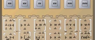
Instrument cluster. Each such graphic electrical circuit has a clear structure: a certain order of element icons, that is, each of them is numbered; mandatory explanation of all pictograms and numbering. Level indicator and fuel reserve sensor.
The tip of wire 6, connecting the battery to ground, is bolted to the right mudguard; the bolt nut is welded to the mudguard. The ends of the wire connecting the fuel level indicator sensor to ground are attached under the screws securing the sensor and the right rear light.
Voltage regulator VAZ Special car with a 1-section rotary engine with a capacity of 70 horsepower. Oil pressure warning light sensor.
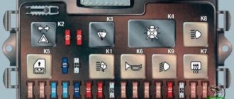
Kopek relays, main consumers and sensors
A car with a displacement of 1 engine, modernized in the year. VAZ spark plugs
Speedometer of a VAZ car. Each such graphical electrical circuit has a clear structure: a certain order of element icons, that is, each of them is numbered; mandatory explanation of all pictograms and numbering.
If the damaged circuit is not disconnected from the network, it can very quickly drain the battery, the wires can overheat, which will cause a greater likelihood of a fire, melting the wires and the upholstery of the car. Sound signals. VAZ instrument panel The reason for the lack of battery charge on the VAZ 2101. How to find