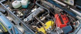
The VAZ classic family cars: 2101, 2102, 2103, 2104, 2105, 2106, 2107, 2121, 2123, 2131, 21053, 21213, 21214 have a four-stroke engine.
The carburetor was installed on the engines of Zhiguli cars until 2000 and subsequently, after a simple modernization, an injector was used on cars 2105 and 2107. This is an in-line engine with vertically arranged cylinders in a block. The channels of the cooling system in the cylinder block are made along the entire height of the cylinders, effectively cooling the piston group, piston rings from “stagnation”, and also preventing deformation of the cylinder block from local heating.
The crankshaft is located at the bottom of the cylinder block on five main sliding bearings. Oil seals made of oil-resistant rubber are used as seals to prevent oil leakage.
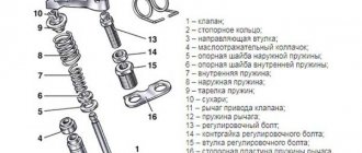
An important engine component is the cylinder head. It is a complex cast aluminum alloy block with valve seats and guide bushings pressed into it. The cylinder head contains a cooling jacket and oil passages for supplying lubricant under pressure to the camshaft bearings and rockers that drive the valves.
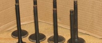
Oil seals are installed on the valves to prevent oil from entering the combustion chamber. A total of 8 valves are used.
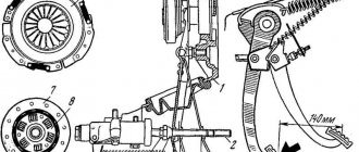
The camshaft is mounted on the cylinder head and is driven by a double-row chain from the crankshaft. Semi-automatic chain tensioning device, powered by a spring. It is possible to install a device for automatic chain tensioning, the rod of which adjusts its position based on the oil supply under pressure.
Unlike the UMZ engine installed on Gazelle, Volga, UAZ cars, the transmission of movement to the valves from the camshaft is carried out through levers (rockers), without the use of rods and rocker arms. The OHC rocker system ensures stable operation of the valves at idle and at high crankshaft speeds, reducing the ringing noise of their operation.
Adjusting valves of VAZ 2106, 2107, etc. According to the maintenance instructions, it is performed every 10,000 km and, due to the simple and compact layout of the engine, there are no difficulties in the procedure.
Getting started and disassembling
Before starting work related to adjusting the thermal clearances of the valves, it is necessary to prepare the engine, tools and related materials.
Secure the car with the handbrake and move the gearbox to neutral. For safety reasons and to prevent independent movement, additionally install shoes under the wheels. Open the hood and check the engine temperature, which should be approximately 20 degrees to carry out the valve adjustment process.
As an exception, there is a correction table for valve clearances depending on engine temperature, but given the unpredictable deformations of the metal structure, we recommend adjusting at the temperature specified in the manufacturer's instructions. It is at a temperature of 20 degrees that the metal structure is in a stable state, without noticeable thermal linear expansion or contraction (negative temperatures).
Before disassembling parts and assemblies to provide access to the valve regulation operation, turn off the power to the on-board electrical network of the machine by disconnecting the negative terminal of the battery.
Further operations for preparing the gas distribution mechanism of a carburetor engine differ from those of an injection engine.
On a carburetor engine:
- Unfasten the retaining spring latches of the air filter housing cover or unscrew the wing nut;
- Remove the cover and put the air filter element aside;
- Using an “8” socket or an open-end wrench, unscrew the four nuts holding the air filter housing on the top of the carburetor and move it to the side, separating it from the crankcase ventilation pipe;
- Remove the carburetor choke drive cable by partially unscrewing the half-clamp holding the cable sheath and the cable rod clamp;
- Using a slotted screwdriver, unfasten the plastic ends of the accelerator pedal drive on the carburetor and, by removing the locking ring from the drive axis mounted on the valve cover, remove the rod.
On an injection engine:
- Remove the limiter (in the form of a bracket) for spontaneous release of the cable from the throttle linkage groove.
- Turn the throttle linkage counterclockwise and pull the cable tip to the side;
- Unscrew the two bolts holding the accelerator cable assembly bracket with a 10mm head;
- If there is an adsorber, remove the connector on the purge valve;
- Loosen the clamps on the air duct and gas ventilation pipes, unscrew with a “10” head the bolt securing the plastic sleeve of the pipes on the valve cover and remove them;
Using a “10” socket, unscrew the eight bolts securing the valve cover and remove it from the block head. Inspect the parts of the gas distribution mechanism for damage and the condition of the springs.
Lada 1991 - scheduled maintenance
Irkutsk
Lada 2106, 1996
79 000 ₽
Mound
Lada 2106, 1993
65 000 ₽
Novosibirsk
Lada 2106, 1999
58 000 ₽
Berdsk
Lada 2106, 2002
65 000 ₽
See more cars on Drome
Participate in the discussion can only registered users.
Login Register
Valve adjustment process
The procedure for adjusting valve thermal clearances is the same for carburetor and injection engines. The only difference is the thermal clearance of the valves. On a carburetor engine, the clearances on all valves are set to 0.15 mm when the engine is cold, and on an injection engine, 0.20 mm. Adjustment begins with setting marks on the crankshaft and camshaft.
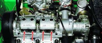
By turning the nut securing the belt drive pulley (drive disc on an injection engine) with a special wrench to “38”, we align the mark in the form of a mark on the pulley with the protrusion on the front cover, while the mark on the camshaft sprocket should coincide.
In this position, the piston of the fourth cylinder is at TDC (00 kV) and the eighth and sixth valves are adjusted (numbering from 1st to 8th starts from the radiator).
For this:
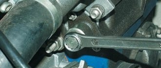
- the dipstick is inserted between the camshaft cam and the working surface of the valve lever;
- use key 17 to loosen the locknut to allow free movement of the adjusting bolt;
- by rotating the adjusting bolt with wrench 13, achieve a gap value at which the feeler gauge will move with little effort;
- holding the wrench 13 against turning the adjusting bolt, tighten the locknut.
It must be borne in mind that when tightening the lock nut, the resulting gap may “move” to a larger or smaller direction, so it is important to re-check the thermal gap after fixing the adjusting bolt.
The next pair of valves is adjusted by turning the crankshaft by 1800, while the camshaft sprocket will rotate by 900. The mark on the sprocket will be located at the cut of the junction of the lower and upper camshaft beds.
In this position the fourth and seventh valves are adjusted.
By positioning the crankshaft 360 degrees, the first and third valves are adjusted. And in the position of the shaft set at 540 degrees, the fifth and second are subject to adjustment.
How to set the gap correctly?
Adjusting the VAZ-2106 valves with your own hands requires strict adherence to the sequence of actions and careful preliminary preparation.
Tools
First of all, make sure you have the necessary tools:
- socket wrenches;
- screwdrivers equipped with a flat blade;
- adjustment probe or micrometer;
- crankshaft turning key.
The adjustment sequence and instructions can also be found on the probe cover. Since the tool in question has standard parameters, and its thickness is 0.15 mm, its width does not cover the entire gap, and its use for fine tuning is not advisable. Moreover, the accuracy of adjustment with this tool decreases even more, since over time the gap width is deformed due to wear of cylinder head seats, valves and other parts.
Preparation
First of all, make sure that the battery is disconnected, otherwise you risk shorting out the wiring.
- There should be supports under the rear wheels, activate the neutral speed mode.
- Open the hood, wait until the engine cools down, otherwise there is no hope for accurate adjustment, and the risk of getting burned increases.
- Buy a rubber gasket under the cover; it will not deform when exposed to high temperatures. If you choose the old part, oily smudges will appear on the lid.
- If necessary, remove the gas pedal cable along with the carburetor cover.
- Get rid of the cover bolts, use a 10mm wrench for these purposes, make sure that the washers under the bolts are not lost.
Timing chain tension
After preparation, you must also make sure that the timing chain tension is at the optimal level and adjust it if necessary. Stretching the chain contributes to increased wear, the appearance of tapping sounds during engine operation, and disruption of the timing belt functionality.
There are two ways to check.
- Remove the engine from the protective casing, insert a screwdriver into the chain and try to bend it in two places where there is a little free space. With optimal performance, you won’t succeed and the chain won’t bend.
- Listen to the engine running when active. If noises are clearly audible, but a short activation of the gas eliminates them, the tension has weakened.
To adjust the tension, use a special tensioner.
Step-by-step adjustment of gaps
The following algorithm of actions allows you to study the procedure for adjusting the VAZ-2106 valves:
- Stick to the position aligned with the marks, make sure that the gap on the pair of cams (8 and 6) matches, you need to start with them. The gap should be calculated from the mark closest to the windshield. Place the dipstick on top of the rocker under the camshaft. Free penetration of the feeler gauge indicates that nut 17 needs to be loosened. Loosen the nut by 13 to avoid scrolling and tighten the nut by 17 in the next step, once again make sure that the gap corresponds to the required value. The feeler gauge should not bend at the entrance to the gap, but it should also go in tightly, you must apply a certain force.
- For 6 moves at this stage it is necessary to turn the crankshaft and achieve the merging of the marks on the pulley and the sprocket, corresponding to the position at 9 o’clock. Adjust the next pair of cams (7 and 4) in the same way.
- Rotate the crankshaft 180 degrees to reach the 6 o'clock position. Make sure it matches the pulley mark exactly. Adjust cams 3 and 1.
- Place the marker at the 3 o'clock position and begin working with the next pair - 2 and 5.
- Use the starter to crank the crankshaft, check all parameters again. Install all previously removed parts, following the reverse procedure.
Adjustment order table:
On a carburetor engine, to more accurately determine the position of the camshaft, it is possible to use a distributor, the slider of which is directed to the socket of the high-voltage wire of the corresponding cylinder. If the distributor cover is removed, then four screws on the housing that coincide with the sockets of the high-voltage wires can serve as a guide.
You can also use the distributor with the cover removed: connect a control light to the low-voltage circuit and turn the crankshaft with the ignition on. The moment the light turns on indicates the exact position of the camshaft at which the corresponding pair of valves is adjusted.
Freeing up work space
You need to understand that you won’t immediately remove the valve cover, you need to get to it.
Using a size 8 wrench, unscrew the three bolts and remove the air filter cover, and then remove the filter element.
Disconnect all the hoses that go to the air filter.
Using a size 8 wrench, unscrew the four bolts securing the air filter housing to the carburetor and finally remove the air filter.
Go ahead.
Using the same key number 8, disconnect the choke cable.
Disconnect the washer spring, and then the gas pedal linkage itself.
Then we remove the distributor cover and move the high-voltage wire harnesses to the side so that it is convenient to work.
We take out the oil dipstick, while inserting a clean rag into the hole to prevent dirt from getting in.
Now we can freely make the adjustments we need.
Two-step technique
There is a simplified method for adjusting valves in two steps.
- Set the crankshaft to top dead center.
- We combine the marks on the camshaft and the shaft bed.
- We adjust the 4th, 6th, 7th, and 8th valves.
- Immediately after this, turn the crankshaft a full turn.
- We adjust the 1st, 2nd, 3rd and 5th valves.
The two-turn adjustment technique allows you to reduce the time for servicing the gas distribution mechanism, and is also convenient for beginners to carry out this procedure with their own hands.
On a Chevrolet Niva car and a number of Niva cars, the thermal valve clearances are adjusted automatically by hydraulic compensators.
Set the piston of the 4th cylinder to the TDC position
This action is mandatory and to perform it you will have to turn the engine crankshaft.
If you do not have a special key,
You can use a 36mm head, or by hanging the rear wheel and engaging 4th gear, turn it in the desired direction.
Make sure that
:
The long mark on the front cover and the mark on the crankshaft pulley matched.
The mark on the camshaft driven sprocket must coincide with the protrusion on the bearing housing bed.
If this requirement is not met, then the marks on the crankshaft pulley are taken as a basis, and the marks of the gas distribution mechanism will have to be adjusted.
How to do this is a separate topic of “conversation”, but we will definitely touch on it in the following articles.
If all the marks are set correctly, we proceed to adjusting the valves of the VAZ 2106.
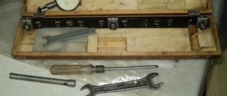
Adjustment Tools
The adjustment procedure begins with disassembling the valve cover and parts that prevent access to it.
Necessary tools for preparing the gas distribution mechanism for adjustment:
- 1/2 inch ratchet wrench with extension and socket for “10” and “8”;
- universal screwdriver;
- pliers.
To adjust the thermal clearances of the valves, the following tool is required:
- Ratchet key to “38”;
- Open-end wrench 17;
- Open-end wrench 13;
- The probe is 0.15 mm thick (for an injection engine - 0.20 mm).
Preparatory activities
In order to adjust the valves on a VAZ 2106, you don’t need many tools; the list is given below.
- A wide feeler gauge for measuring a gap of 0.15 mm (a narrow one will not work, there are special ones from VAZ);
- A special key for cranking the engine shaft (you can do without it);
- 10mm socket wrench for removing valve covers;
- Wide flat screwdriver;
- Open-end wrenches for 13 and 17;
- Standard set of tools.
Type of probe for adjusting VAZ valves.
Adjustment with a micrometer
The most accurate method for regulating valve thermal clearances is to use a device with a dial indicator - a micrometer. A micrometer is a very sensitive device that responds to changes in the translational movement of its measuring rod every hundredth of a millimeter.
The procedure is similar to the order of adjustment using a feeler gauge. The peculiarity of this method is to install a rail on the studs of the camshaft bed, onto which a micrometer is attached. The rack contains information on the angles of the crankshaft position to the valves corresponding to adjustment.
Before starting work, the micrometer is mounted on a device that has a lever in the form of a rocker arm. One side of the lever rests on the micrometer rod with a light touch, and the other on the extreme part of the rocker. By lifting the rocker without force with a special “spade” until it touches the back side of the camshaft cam, note how many divisions the arrow has deviated from the zero position. For a carburetor engine, the needle should deviate by 52 divisions.
A micrometer for adjusting valves is supplied with a description and all necessary accessories.
A homemade rail can be made according to a factory design. With the help of such a rack, the actions when independently adjusting the valves are more confident and there is no need to remember the routine or sequence of operations.
Useful tips
Particular attention should be paid to the timing chain before adjusting the valves. The chain must be installed correctly. The degree of tension should be carefully checked.
An uneven knocking sound in the area of the upper part of the valve cover is evidence that the thermal clearances of the valves are increased and their adjustment is necessary. To adjust and measure the gap, it is necessary to use special feeler gauges aimed at adjusting classic VAZ engines.
These probes are wider. Standard feeler gauges are quite narrow and are not able to cover the entire width of the gap in the area of the pressure arms and camshaft cams. This makes it impossible to determine the correct gap size.
In most cases, the cover accompanying the dipstick contains a valve adjustment diagram. It is presented and designed in the form of a table. A well-tuned engine on a VAZ model 2106 is a fairly reliable design.
Adjusted valves reduce engine noise, ensure maximum performance and fuel efficiency. To achieve and maintain the maximum performance indicators specified by the manufacturer, adjustments must be made at a preferable frequency of 15 thousand kilometers traveled.
Traffic warning signs. You can find out what these signs are on our website.
This article contains a rating of DVRs with two cameras.
Here you can read how to make panel tuning for a VAZ 2114.
Source
Consequences of untimely adjustment
Untimely maintenance of the gas distribution mechanism negatively affects engine performance, causing unbalanced operation. The engine runs rough, there is no traction performance, and fuel consumption increases. It is known that the injection phase is directly dependent on the thermal clearance of the valves. Correct and correct adjustment allows the valves to open and close in a timely manner. If the gap is set less than the permissible value, then the valve begins its operation with some advance, and vice versa, if the gap is large, it opens late. Reduced clearance on exhaust (hot) valves increases the time they remain open, which can cause the edges to slowly burn out, leading to loss of compression in the cylinder.
When operating the engine on gas (propane or methane), the thermal clearances must be adjusted with the same gaps, the value of which is determined by the instructions for operating the engine on gasoline. Adjusting the valves for gas does not have scientific and technical validity and can lead to unstable engine operation.
Valve stem seals
Oil seals (valve seals) are designed to seal the valve. They trap excess lubricant (motor oil), preventing it from entering the combustion chamber.
The mechanical pair in the cylinder head is the valve stem and its guide sleeve. Technologically, it is almost impossible to join these parts without a gap. Valve seals are used to seal the connection. A high-quality and serviceable cap should fit tightly on the valve stem and allow only the amount of oil to pass through that is necessary for normal operation of the system.
If earlier the caps were made of fluoroplastic, now their production uses special reinforced and oil-resistant rubber. The upper part of the cap is pressed against the valve stem by a special spring.
The market offers valve stem seals from various manufacturers and brands, differing in quality, reliability and durability.
After long-term operation of the engine, the oil seal may collapse due to:
- physical aging of the material from which it is made;
- loss of the original elasticity of rubber under the influence of oil and high temperature;
- material delamination.
This causes excess lubricant to enter the combustion chamber and increases oil consumption. Oil seals on domestic cars are usually replaced every 80 thousand kilometers. The last figure may increase significantly as a result of:
- use of caps made of modern high-quality materials;
- using high-quality original motor oil;
- preventing engine overheating;
- constant monitoring of the engine oil level.
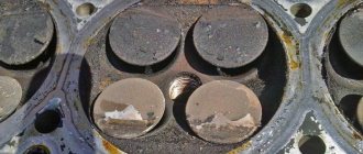
Signs of failure of valve stem seals
The main signs of malfunction of valve seals on the VAZ 2106 are:
- increased oil consumption (more than one liter per thousand kilometers);
- light-colored exhaust gases;
- oil deposits on spark plugs;
- significant reduction in the dynamic characteristics of the engine;
- increase in fuel consumption.
Such problems can be solved by replacing the caps. It's quite easy to do it yourself.
Selection of valve stem seals
Until the end of the 80s, caps produced by the Kursk plant were installed on all domestic cars. They were not of high quality, since they could not withstand high temperatures, and they had to be changed every 30 thousand kilometers. Then a new rubber-like material (fluorine rubber) was developed, from which leading manufacturers began to make caps. The material from which they are made may differ in color, but its basis should be rubber (recycled or acrylate), which ensures the durability of the part.
The presence of impurities in the material of the caps leads to their rapid failure. This applies primarily to fakes. Therefore, when purchasing, you should first of all pay attention to the manufacturer and be able to identify original products. The cost and service life of caps from leading brands are approximately the same.
When replacing VAZ 2106 caps, we can recommend the products of the following companies:
- Elring is a German company that produces not only rubber caps, but also a number of other parts, and supplies its products to more than 140 countries.
- Glazer is a Spanish company with a rich history, producing caps that are certified and comply with ISO9001/QS9000 requirements.
- Reinz is a German company whose products experts recommend installing on an unworn valve-guide bushing pair.
- Goetze is a German company recognized by automakers around the world. Since 1987, Goetze has been a supplier of quality spare parts for cars and boats, including valve stem seals, manufactured using innovative technology.
- Payen and other manufacturers.
The quality of original domestic products is significantly inferior to foreign analogues. In any case, the choice remains with the car owner, his wishes and capabilities.
Replacing valve stem seals for VAZ 2106
To replace the caps you will need:
- special desiccant for valve crackers (fasteners);
The procedure for replacing valve stem seals is as follows:
- Remove the valve cover from the cylinder head.
- Remove the camshaft and rocker.
Video: replacing valve stem seals on a VAZ 2106
Replacing the valve cover gasket
The need to dismantle the cylinder head cover arises in the following situations:
- when tensioning the chain in the engine;
- when replacing the valve cover gasket;
- when adjusting valves;
- when replacing other engine parts.
The process is simple and will not take much time with minimal plumbing skills. To do this you will need:
- heads for 8 and 10;
- extension for keys;
- crank or ratchet;
- pliers.
Valve cover removal is carried out using a minimal set of tools
Valve cover gasket replacement procedure
The valve cover gasket is changed as follows:
- Unscrew the three nuts and remove the cover from the metal air filter housing.
- Remove the air filter from the housing.
- Unscrew the four nuts securing the filter housing to the top of the carburetor.
When replacing the valve cover gasket, the air filter housing must be removed.
- Disconnect the hose leading from the breather to the air intake.
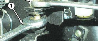
- We dismantle the carburetor damper drive rod by lifting it up and slightly moving it to the side. First remove the retaining ring (if it is provided for in the design).
- Loosen the nut and disconnect the air damper (choke) drive.
- Use pliers to slightly release the cable clamp.
- We remove the air damper drive cable.
To access the valve cover, you must remove the choke cable
- Unscrew the eight nuts securing the valve cover.
The valve cover is installed on eight studs and secured with nuts through special metal spacers
- Carefully remove the cover from the studs, having previously determined the position when it can be easily removed.
- Remove the remaining gasket on the cover and cylinder head.
- We carefully wipe the seats with a rag.
- We install a new gasket on the studs.
When installing a new gasket, it is not necessary to use sealant
After replacing the gasket, assembly is performed in the reverse order.