Checking engine sensors are largely similar to each other, despite the fact that these devices measure different physical quantities and values. To test most of them, an electronic multimeter is used that can measure the value of electrical resistance and voltage. However, most sensors can be tested using other methods, depending on their operating principle. Before checking, the sensors must be removed from their mounting location, because in most cases, checking directly on site is impossible.
Let's consider the purpose and methods of checking the main sensors under the hood of any modern car. Since if at least one of them fails, the operation of the entire engine will be disrupted.
Mass air flow sensor
As the name implies, abbreviated as MAF, it measures the volumetric amount of air intake by the engine. The unit of measurement in this case is kilograms per hour. For most cars, this sensor is installed on the air filter housing or on the intake manifold. Its device is simple, so it rarely fails. However, in some cases it may record and provide incorrect information.
For example, if the readings from it are overestimated by 10...20%, problems arise in the operation of the engine, in particular, the idle speed may “float”, the engine “chokes” and starts poorly. If the readings from the sensor are lower than they actually are, then the dynamic characteristics of the car decrease (it does not accelerate, it drives slowly uphill), and fuel consumption also increases.
Correct operation of the mass air flow sensor is highly dependent on the condition of the air filter. So, if the latter is very clogged, then there is a risk of debris falling on the sensor - grains of sand, dirt, moisture, and so on, and this is very harmful to it, and leads to the fact that the sensor provides incorrect information. This can also happen if the machine has a zero resistance filter (or there is simply no filter).
An interesting feature of the mass air flow sensor is that cars equipped with it cannot be tuned by increasing engine power. In particular, this applies to VAZ engines, which some car enthusiasts “pump” up to a power value of 150...160 horsepower. In this case, the sensor will obviously not work correctly, since it is simply not designed for such an amount of air volume passing into the engine.
For standard VAZ engines, the mass air flow sensor at idle speed should record the passage of about 8...10 kilograms of air per hour. When the speed increases to 3000 rpm, the corresponding value increases to 28...32 kg/hour. For engines similar in volume to VAZ ones, these values will be close or similar.
Checking the mass air flow sensor involves measuring the DC voltage it produces using an electronic multimeter.
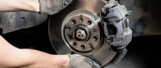
ABS
This system is designed to prevent the wheels from completely locking when braking. Therefore, the device necessarily contains wheel speed sensors. Their designs are different. They can be passive or active.
- Passive sensors are mostly inductive sensors. The sensor itself consists of a steel core and a coil with a large number of turns of thin enameled copper wire. In order for it to perform its functions, a steel toothed ring is pressed onto the wheel drive or hub. And the sensor is fixed so that when the wheel rotates, the teeth pass close to the core and induce electrical impulses in the coil. Their repetition frequency will be a proportional expression of the speed of rotation of the wheel. The advantages of a device of this type: simplicity, lack of power and low cost. Their disadvantage is that the pulse amplitude is too small at speeds up to 7 km/h.
- Active, which come in two types. Some are based on the well-known Hall effect. Others are magnetoresistive based on the phenomenon of the same name. The magnetoresistive effect consists of a change in the electrical resistance of a semiconductor when placed in a magnetic field. Both types of active sensors are distinguished by sufficient pulse amplitude at any speed. But their design is more complex and the cost is higher than passive ones. And the fact that they need food cannot be called an advantage.
Lubrication system
Automotive sensors that monitor the operating parameters of this system are of three types:
- Oil level sensor. It has, perhaps, the simplest device. This is a float that moves vertically in the oil pan along a guide and closes the contacts when the oil surface reaches the minimum permissible level. Adding oil causes the level to rise and the contacts to open.
- Oil pressure sensor (OP). Most often it is electromechanical. Its device is divided into two parts by an elastic diaphragm. Which, under the influence of oil pressure, is deformed and moves the potentiometer slide. As a result, the resistance between the output terminal and ground changes. When oil pressure drops, the diaphragm returns under the action of a spring.
- Insufficient (emergency) pressure sensor. It consists of a diaphragm with a spring, the same as that of the DD, and a contact normally closed to ground. One of the contacts of the emergency oil pressure warning light in the instrument cluster is connected to its terminal. When the ignition is turned on, power is supplied to the other contact of this light bulb, so it begins to glow. After starting the engine, the diaphragm, under the influence of oil pressure, opens the contact of the sensor terminal with ground. At the same time, the control lamp goes out. A decrease in oil pressure below the permissible level leads to the fact that, under the action of a spring, the terminal closes to ground and the lamp lights up again, signaling a lack of pressure in the system.
Throttle position sensor
The sensor is designed to record the position of the throttle valve at a specific point in time. The corresponding position changes depending on whether the accelerator pedal is pressed and how far. Typically, the throttle position sensor is installed directly on the throttle and/or on the same axis as the throttle. It is noted that if an original high-quality sensor is installed on the machine, then most likely there will be no problems with its operation. However, there are many counterfeit low-quality sensors on sale (for example, made in China), which, firstly, do not last long (about a month), and secondly, provide incorrect information, which leads to the engine operating in suboptimal conditions for it.
For example, if the throttle position sensor partially fails, problems arise in the car’s response to the driver’s actions in relation to the gas pedal. For example, dips appear when it is pressed, a spontaneous increase in speed, and its “swimming”. Also, if the throttle position is faulty, jerks and dips may occur when the engine is running under load. In a word, the accelerator pedal, as it were, “begins to live its own life.”
There are known cases when TPSs failed due to the fact that they were damaged by a powerful water jet at car washes. To the point that they can simply be knocked off their seat. Therefore, you need to carefully monitor this when washing cars yourself or in a specialized establishment. In general, the throttle position sensor is a fairly reliable device. However, if it fails, it cannot be repaired, so it should only be replaced completely.
check the throttle sensor using a multimeter that can measure DC voltage in the range of up to 5 volts.
Replacing the air flow sensor
It is important to know
The mass air flow sensor is purchased for a specific car model. The use of analogues is not recommended, as this may lead to malfunctions of the device.
What will you need?
To complete the task you will need:
- key head with a knob;
- Phillips screwdriver;
- wrench 10;
- new mass air flow sensor.
Step-by-step instruction
| Image | Step |
| |
| The sensor is fixed with two bolts on the body of the filter device. To unscrew them, use a key or ratchet. | |
| After removing the last fastening, the regulator is dismantled. A new sensor is being installed, after which a chip with wires must be inserted into the mass air flow sensor. |
Coolant temperature sensor
It also has other names - temperature sensor, coolant sensor. As the name implies, its task is to record the temperature of antifreeze or antifreeze and transmit this information to the engine electronic control unit (ECU). Based on the information received, the control unit adjusts the richness of the air-fuel mass entering the engine; accordingly, the colder the engine, the richer this mixture will be. The coolant temperature sensor is most often located on the exhaust pipe of the cylinder head (although there may be other options, this depends on the specific car model).
Essentially, this sensor is a thermistor - that is, a resistor that changes its internal electrical resistance depending on the temperature of its control element. The lower the temperature, the higher the resistance, and vice versa, the higher the temperature, the lower the resistance. However, the sensor supplies the ECU with a voltage value rather than a resistance value. This is implemented by the sensor control system when a 5 Volt signal is supplied to it through a resistor with a constant resistance, which is located inside the control controller. Therefore, along with the resistance, the output voltage also changes. So, if the antifreeze temperature is low, the output voltage will be high, and as it warms up, the voltage will decrease.
Signs of sensor failure:
- Spontaneous activation of the cooling fan when the engine is cold;
- the cooling fan does not turn on when the engine is hot (at extreme temperatures when it should turn on);
- problems with starting the engine “hot”;
- increased fuel consumption.
To be fair, it is worth noting that the sensor design is quite simple, and there is simply nothing to break there. However, in some cases (for example, due to mechanical damage or old age), the electrical contact inside the sensor may become damaged. The second possible cause of failure is a break in the wiring from the sensor to the ECU or damage to its insulation. As is the case with other sensors, this unit cannot be repaired and only needs to be replaced with a new one.
check the coolant temperature sensor either directly at its seat in the engine or by first removing it.
Sensors in our internal combustion engines: purpose and operating principle
Mass air flow sensor
The purpose of the mass air flow sensor (MAF) is to monitor the operation of the power unit while the system generates electrical voltage through the air entering the engine.
Based on the data collected by the sensor, the most productive operation of the motor is built, during which the flow of air into the cylinders allows it to be uninterruptedly converted into electric current.
The working part of the sensor - a platinum thread - is a sensitive anemometer. It heats up to a constant temperature, which is maintained using a thermal relay and an electronic control unit.
The air flow passing through the sensor cools the filament, then the system control module increases the current supply to it, as a result of which the heating temperature of the filament continues to increase until it reaches its constant value. It follows from this that the strength of the current required to heat the filament depends solely on the speed of air flow through the sensor. And through the secondary converter in the sensor system, electrical voltage is generated.
During operation, various deposits accumulate on the sensor thread, contaminating it and deteriorating the performance of the entire device.
Effective thread cleaning is possible only by burning with a pulsed current at a temperature of about 1 thousand degrees.
However, rinsing the dirty platinum sensor filament with solutions containing ether or ketone compounds is strictly prohibited, since they:
— have a detrimental effect on the compound;
- have the ability to cool the crystal, as a result of which its structure is damaged;
— wash off the so-called mask from the surface of the crystal (the protective polymer layer in its center).
You should not even try to wash the sensor thread with various solvents and aerosols containing acetone and ethyl, and you should also not clean the anemometer thread with a cotton wool soaked in gasoline, wound on a match, or a wooden stick. Such manipulations will not bring any effect, but will only worsen the performance of the mass air flow sensor.
You can use VD-40 as a flush, but it is worth considering that it contains diesel fuel and acidic compounds. The Vedashka rinses well, however, it leaves behind a specific film on the surface, which must be removed for normal operation of the sensor. It is better to wash it off with alcohol compounds (distilled water and any alcohol). As practice has shown, isopropyl alcohol is most suitable for this purpose. The most effective way is to wash the crystal using an ordinary medical syringe with a small-diameter needle. Before washing, the sensor and flushing liquid must be warmed up, for example, using a hair dryer.
Throttle position sensor
This element is installed on the throttle block next to the drive, and is intended to control the position of the gas pedal. It is worth noting that when washing the power unit you should be extremely careful so as not to damage this sensor.
Despite the fact that the throttle sensor is designed for long-term use, it still sometimes fails and fails. Its breakdown is indicated by increased idle speed, jerking and unstable engine operation while driving.
Knock sensor
It is located on the cylinder head between cylinders (II and III). Depending on the design features, the following types of these elements are distinguished:
— broadband (presented in the form of a tablet);
- resonant (looks like a barrel).
These sensors are not interchangeable, that is, if one fails, it cannot be replaced with another type.
The working resource of the element is enormous. The only thing that is necessary is to regularly clean the connector contacts from oxidation. This sensor works on the principle of a piezo lighter. That is, as the level of detonation increases, the electrical voltage begins to increase.
The sensor measures the level of detonation in the power unit and, depending on this, controls the ignition timing. In case of increased detonation, ignition will be delayed. If the sensor stops functioning, the engine will begin to operate incorrectly and fuel consumption will increase.
It has a hexagonal design, inside of which there is a special piezoelectric element that generates electromotive force due to the effect of sound vibrations on its body. It turns out that the knock sensor is a kind of transmitter of sound vibrations, thanks to which the EFI unit has access to the processes occurring inside the engine.
The voids between the body and the piezoelectric element of the sensor are filled with a compound of a special composition. In addition to its protective purpose, the compound has one more purpose: its presence makes it possible to develop an amplitude-frequency characteristic that is as close as possible to the frequency of detonation processes inside the power unit.
When detonation occurs in the internal engine space, the sensor measures its level and transmits a signal to the EFI unit, which automatically adjusts the ignition timing until the level of detonation decreases or disappears completely.
As a result, thanks to the presence of a knock sensor in the power unit system, the most favorable composition of the fuel mixture is formed. This concept, characterized in automotive slang by the phrase “knock of fingers,” characterizes the breakdown of the knock sensor. At the same time, engine performance sharply decreases and fuel consumption increases.
Oil pressure sensor
This control element is located in the main oil pipeline network. The sensor is powered from the vehicle's electrical network and has an indicator on the dashboard. In addition to the indicator, the instrument panel may have an oil pressure controller indicating its value.
Quite often, this sensor is a monitoring part of the engine control system, which, when a critical level of oil pressure is reached, turns off the power unit.
In addition to the oil pressure sensor, a sensor can be installed that monitors the temperature of the engine oil in the system.
Antifreeze temperature sensor
In the design of the power unit, this sensor takes its place between the thermostat and the cylinder head. It has two contacts, and the operation of the device is based on the following principle: the lower the engine temperature, the more enriched the working mixture can be obtained.
In the cooling system, the sensor is represented by a specially designed resistor (thermistor), which changes its resistance as the temperature of the coolant changes. The higher the temperature, the lower the resistance, and vice versa - the lower the temperature, the higher the resistance of the thermistor. It is known that changes in coolant temperature have different effects on engine operation.
Its design is quite reliable. It can fail only due to a lack of contact at its terminals or inside the device.
Its malfunction can be judged by the start of operation of the fan while the engine is still in a cold state, the impossibility or problems with starting a warmed-up power unit, and an increase in fuel consumption.
Lambda probe
Or, in simple terms, an oxygen sensor. Its purpose is to determine the amount of oxygen in the exhaust gases of a car. This electrochemical element is located in the muffler design.
The absence of oxygen in the fuel mixture indicates its enrichment, and, conversely, its increased content reduces enrichment. Therefore, the lambda probe is designed to form the correct composition of the working mixture. More details about lambda here.
Leaded gasoline will have a detrimental effect on the operation of the oxygen sensor, and if it breaks down, increased fuel consumption and an excess of harmful compounds in the vehicle's exhaust gases are guaranteed.
PCV (crankshaft position) sensor
A fairly strong and reliable element, the design of which is a coil of wire with a magnetic core inside. It is located in the space of the pulley, and according to the marks marked on the pulley, it reads the position of the crankshaft. The element generates a signal as soon as the position of the toothed disk located on the crankshaft changes. Based on this signal, the control unit monitors the working processes occurring inside the cylinder and controls the supply of the fuel mixture and spark.
If it breaks down, the operating speed of the engine will drop sharply, and in the worst case, the power unit will stop completely.
Phase sensor or camshaft position sensor (CPR)
It is included in the design, as a rule, of eight- and sixteen-valve engines, on which it is located immediately behind the camshaft pulley of the intake system on top of the cylinder head, and is intended to form fuel injection into a separate cylinder. Its breakdown disrupts the supply of the fuel mixture, which causes its sudden enrichment, resulting in increased consumption.
Idle speed controller
An indispensable element in the engine design that regulates engine idle speed, ensuring its stable and most productive operation. The design of the device consists of a stepper motor with a spring-loaded cone-type needle.
When the power unit is idling, air circulates past the closed throttle valve. This is possible thanks to the conical needle of the sensor, which regulates the cross-sectional diameter of the additional air supply line. Thus, the sensor determines the optimal amount of oxygen required for the smooth and productive operation of the unit.
The location of the regulator is the throttle body. Here you need to pay attention to the fact that it is secured with two screws, the heads of which in most cars are covered with a layer of varnish or are simply drilled out, which presents some hindrance when removing the idle speed control. Therefore, it is often necessary to resort to removing the damper body in order to replace the regulator or clean the contaminated air line.
Since the regulator is an actuator type device, its system diagnostics are not provided. Therefore, if it breaks down, the “Check Engine” error on the instrument panel may not light up.
The following factors indicate its malfunction:
— “floating” engine idle speed;
— often the power unit stalls after switching off the gear;
— a cold start of the engine is not accompanied by an increase in idle speed, as it should be;
— instability of idle speed when the load is turned on.
It is necessary to remove the idle speed control only when the battery is disconnected. To do this, remove the connector from it and unscrew the screws securing the sensor. The regulator is installed in the reverse order. The only thing that needs to be done at the time of installation is to lubricate the seal on the flange. Motor oil is ideal for this.
The relationship of different types of sensors in the engine idle speed control system
The amount of air in the engine is controlled by the mass air flow sensor described above, and depending on its volume, the ECU calculates the supply of an enriched working mixture to the engine.
Using the crankshaft position sensor, the control unit determines the speed of the engine unit, and based on this, the idle speed control system controls the air supply, bypassing the closed throttle valve.
During parking, the control unit maintains a constant idle speed on a warm engine. If the power unit is cold, the system increases it by adjusting the idle speed, ensuring the engine warms up at high speeds. Thanks to this, movement is allowed without warming up the power unit.
All of the sensors listed are found on most modern cars, and now it will be much easier for you to navigate the diagnostic results and purchase the necessary spare parts at a car store.
Knock sensor
The knock sensor (abbreviated DD) detects the appearance of detonation knocks directly in the engine. Typically, the knock sensor is installed directly on the engine block, most often between the second and third cylinders. Currently, there are two types of such sensors - resonant and broadband. The first of them (resonance) are considered obsolete and can only be found in engines of older designs. The resonant sensor is designed for a certain sound frequency, which corresponds to micro-explosions in the motor. A wideband sensor records sound waves in the range from 6 Hz to 15 kHz. The relevant information is transmitted to the electronic control unit, and the control unit then decides whether detonation occurs or not. And if it does exist, the ECU automatically shifts the ignition angle to avoid its recurrence.
Signs of failure of the knock sensor are the following factors:
- loss of dynamic characteristics of the car (it does not accelerate, does not pull well uphill);
- idle speed “floats”, they can also be unstable in operating mode;
- increased fuel consumption.
Checking the knock sensor can be done in two ways - by measuring the value of the output resistance, voltage, or using an oscilloscope to watch its operating mode in dynamics.
Oxygen concentration sensor
Another name for the sensor is lambda probe. The main task of the unit is to record the amount of oxygen in the exhaust gases. As a rule, it is installed next to the catalyst or on the exhaust pipe of the muffler. In some car models, the design provides for the use of two oxygen sensors - one before the catalyst, and the second after. The relevant information is traditionally transmitted to the electronic control unit, and it then makes a decision on the supply of fuel to the engine, adjusting the composition of the air-fuel mixture (poor/rich). If oxygen is detected in the exhaust gases, it means the mixture is lean; if not detected, it means it’s rich.
The oxygen sensor itself is quite reliable and rarely fails. However, if this happens, then the emission of harmful substances along with exhaust gases into the atmosphere increases. Externally, the failure of the lambda probe can be determined by increased fuel consumption. A conditional disadvantage of the sensor is its relatively high price compared to other car sensors.
Checking the oxygen sensor is carried out both visually and with a tester. The method of measuring voltage and sending a signal will depend on how many contacts a particular lambda has.
Lambda probe in a car
lambda probe aka oxygen sensor
Some sensors in a car and their purpose remain in the shadows until the driver encounters a malfunction in the system. The lambda probe is known as an oxygen sensor; it is needed to measure the level of oxygen that remains in the exhaust manifold after combustion of the fuel mixture. This system is found in all modern cars.
The function of the probe is not limited to compiling the optimal fuel-air mixture. Thanks to the sensor, it is possible to reduce the content of harmful substances in the exhaust. This is important for the environment and people. A faulty probe should be repaired immediately.
Increased fuel consumption may indicate a sensor malfunction. The meter regulates the amount of fuel mixture, so its failures lead to increased consumption. You can correct the situation at a service center, where they will conduct diagnostics and identify the cause of the malfunction.
Crankshaft position sensor
Its abbreviated name is DPKV. This is one of the main sensors of an internal combustion engine, and all its operation depends on it. The task is to generate an electrical signal about a change in the angular position of a special toothed disk mounted on the crankshaft. Based on this information, the electronic engine control unit decides at what time to supply fuel to which cylinder and light the spark plug. Typically, the crankshaft position sensor is installed on the oil pump cover. Structurally, the device is very similar to a regular magnet with a thin wire.
If the DPKV sensor fails, two situations may occur. The first is that the engine stops working completely because the synchronization of fuel supply, spark, and so on is lost. This happens most often. However, in some cases, the electronic control unit switches the engine to emergency mode, in which engine speed is limited to 3000...5000 rpm. This will activate the Check Engine light on the dashboard.
Checking the crankshaft position sensor is performed using three methods: measuring resistance, inductance, and an oscilloscope.
Powertrain control sensors
There are instruments related to engine management. These include sensors:
- position, speed;
- determining the amount of air;
- promoting blood pressure control;
- determination of temperature indicators;
- warning about the likelihood of detonation and monitoring the activity of the engine and fuel system.
This also includes the air sensor. The article talks about just a few possible sensors. Their number and quality are determined by the class to which the car belongs and its price. The more expensive and technologically advanced the car, the greater the number of sensors built into it.
Share:
Speed sensor
It is located on the gearbox and records the shaft rotation speed, transmitting the corresponding information to the electronic control unit. And the ECU already calculates the speed based on the information received. In cars with a manual transmission, the relevant information is transmitted to the speedometer located on the dashboard. In cars equipped with an automatic transmission, based on information including from it (but not only), a decision is made to shift gears up or down. Also, based on information from the speed sensor, the car’s mileage is calculated, that is, the operation of the odometer.
The sensor supplies the electronic control unit with voltage pulses in the range from 1 to 5 Volts with a frequency proportional to the wheel speed. Based on their frequency, the device calculates the speed of the machine, and based on the number of pulses, the distance traveled.
The sensor itself is a fairly reliable device, but in some cases the plastic gear wears out and its contacts may oxidize, which leads to ECU problems. In particular, the control unit cannot understand whether the car is standing or driving, and at what speed. Accordingly, this leads to problems in the operation of the speedometer, as well as gear shifting in an automatic transmission. Also, when the sensor fails (oxidation of the contacts), reduced idle speed values are noted; during sharp braking, the engine speed “sags” greatly, and the dynamic characteristics of the car decrease (it accelerates poorly, does not pull). On some cars (for example, on some Chevrolet models), the electronic control unit turns off the engine in emergency mode, and movement becomes impossible.
Checking the speed sensor requires using one of three available methods.
Sensor restoration
Before starting work on the car, it is necessary to deactivate the ignition and disconnect the plug with wires from the regulator.
What will you need?
To carry out the procedure you will need:
- rags;
- set of wrenches;
- cleanser;
- a screwdriver if its use requires dismantling the flow meter.
Selecting a cleaner
Products that can be purchased at the store to clean the controller:
- WD-40. A universal product that can also be used for cleaning.
- Liqui Moly. The use of such a composition is relevant for working sensors. The product is universal and can be used on both diesel and gasoline engines.
- Alcohol.
- Cleaning agent for carburetor engines.
- Liquid key. This product is sold as a spray.
- Air Senso Clean.
Good to know
Do not use cotton swabs or compressed air to clean the device. It is important that the cleaning agent does not contain acetone or ether.
Algorithm of actions
| Image | Step |
| The user must remove the hose connected to the sensor; to do this, use a wrench to unscrew the screws securing the device to the air filter housing. The dismantling algorithm may differ depending on the design features of the car. | |
| |
|
Camshaft position sensor
Similar to the DPKV, the camshaft position sensor (abbreviated DPRV) reads information about the angle of its position and transmits the corresponding information to the ECU. Based on the information received, the control unit makes a decision to open the fuel injectors at a certain point in time. Old injection engines (up to about 2005) did not have a camshaft position sensor installed. Because of this, fuel injection into the intake manifold on such engines was carried out in pairs-parallel mode, in which two injectors open simultaneously, which is characterized by excessive fuel consumption.
On engines on which DPRV is installed, so-called phased fuel injection is performed. That is, only one injector nozzle opens, where fuel should be supplied at the moment. As for the location of the sensor, on eight-valve engines it is mounted at the end of the cylinder head. On sixteen-valve power units, this sensor is also usually located on the cylinder head, near the first cylinder.
If the camshaft position sensor fails, the electronic control unit switches the engine to emergency mode, in which the injectors operate in pairs-parallel mode, opening simultaneously. This leads to excessive fuel consumption by 10...15%, in some cases the engine “troubles”. Typically, this generates an error signal in the ECU and activates the Check Engine light on the dashboard. Therefore, it is necessary to perform additional diagnostics using an electronic error scanner.
The DPRV sensor can be checked using a multimeter and/or an oscilloscope.
Let's sum it up
Modern cars use a minimum of sensors and a maximum of computer control. Some Japanese cars have already implemented systems for changing compression in the cylinders, which is why the volume of the power unit even changes at the command of the computer. But budget cars still have standard engines with a set of 15 sensors that show quite regular problems. This leads to the fact that the owner is forced to regularly visit service stations and pay money for diagnostics, which do not always bring the desired results.
Be careful and get more information about what problems are caused by the failure of a particular sensor. It is quite possible that the engine does not require any attention, and you have already planned a major overhaul of the power unit. Perhaps the culprit of the problem was a malfunctioning sensor, which should simply be replaced. Very often these sensors are not that expensive, and sometimes you can choose even cheaper analogues and operate them quite adequately. So it’s worth doing research on the car if the engine performance does not suit you.
Anti-lock braking system sensor
As the name implies, this unit is key to the operation of the anti-lock braking system (abbreviated as ABS). On vehicles equipped with this system, there is one such sensor on each wheel. Their task is to record the speed of rotation of the wheel at a specific moment in time. The location method for cars may be different, but in any case the sensor will be located in close proximity to the wheel rim, in the area of the hub. Usually signal wires go to it, along which you can determine the exact location of the sensors on the front and rear wheels.
As a rule, the sensors themselves are quite reliable and rarely fail, except due to mechanical damage associated with the fact that they are installed in close proximity to the wheel and road. More often, the wiring going to/from them is damaged. It may fray or the insulation on the wires will be damaged. If the electronic control unit “sees” that incorrect information is coming from the sensor/sensors, then it activates the Check Engine warning light on the dashboard, and simply turns off the ABS system in emergency mode. Naturally, this leads to a decrease in driving safety.
Checking the ABS sensor is carried out in various ways - by measuring resistance, voltage or using an oscilloscope (the most advanced method). On newer cars, Hall effect sensors are installed as ABS sensors.
ABS sensor
Before purchasing a used car, special attention should be paid to the special ABS sensor. For testing, a conventional modern multimeter with full functionality is used. A more accurate check is performed at service stations using an oscilloscope.
We connect the device to the contacts, measure the resistance and compare it with the basic indicators, which are specified in the documentation for your car. During the measurement, it is necessary to shake the wires. If the multimeter readings change, this indicates an open circuit.
In addition to resistance, the ABS sensor is also checked for voltage. To do this, switch the multimeter mode from measuring resistance to measuring voltage. Next, we spin the car wheel up to 50 rpm and measure the voltage. The indicator should not exceed 2 V.
Hall Sensor
Sensors whose operation is based on the Hall effect (which is why they are called that) are used in electronic ignition systems. Their use provides two main advantages - the absence of a contact group (a problematic unit that can sometimes burn out), as well as providing a higher voltage on the spark plug (30 kV instead of 15 kV). However, similar sensors are also used in other systems of modern cars - brake, anti-lock braking, and tachometer operation. However, the principle of testing is almost the same and consists of measuring the resistance and/or voltage on the sensor with an electronic multimeter.
If the Hall sensor located in the electronic ignition system fails, the following external signs of this failure occur:
- problems with starting the engine, up to complete inability to start it;
- problems with the engine idling (interruptions appear, unstable engine speed);
- twitching of the car when driving in a mode where the engine has reached high speeds;
- The engine stalls while the car is moving.
A Hall sensor is a fairly simple and reliable device, but in some cases it can “lie,” that is, produce incorrect data. If, as a result of the test performed, it turns out that the sensor is completely or partially out of order, then it is unlikely to be repaired (and there is no point in doing so), so it is necessary to replace it. The sensor in the ignition system of a carburetor car is located in the distributor.
Checking the Hall sensor in the ignition system can be done in one of four ways.
Types of engine sensors
The difference in the basic operating principles gives us the right to classify the sensors as follows:
- Potentiometers or position sensors
The design consists of a resistive arc-shaped track, one side connected to ground, and the other receiving power. If a voltage of 12V is applied to this output, then zero voltage is created at the opposite output. Sliding along an arc, the slider takes voltage readings over the entire area. As it passes from one end to the other, the voltage on it changes from 12V to 0. These voltage changes are the signals transmitted to the ECU.
- Piezoelectric
- Thermistor or temperature sensors. These are semiconductor resistors in which a change in temperature leads to a change in voltage in the semiconductors. These differences are recorded in the ECU, on the basis of which the operation of the systems is regulated.
- Hot-wire or pressure sensors
Oil pressure sensor
There are two types of oil pressure sensors (or oil pressure sensors for short) - mechanical (considered obsolete and installed, accordingly, on old cars) and electronic (modern, installed on most modern cars). Regardless of its type, the position of the oil pressure sensor is usually located in the area of the oil filter in the engine compartment.
Oil pressure sensors are fairly reliable devices (although the mechanical one fails more often, since its design has moving electrical contacts that fail over time), but malfunctions in their wiring occur (broken wires, damaged insulation). Signs of sensor failure will be problems with indicating pressure and/or oil level in the engine.
Please note that if problems arise in the operation of the oil pressure sensor, diagnostics must be performed as quickly as possible, since the low level of lubricating fluid in the engine crankcase is a critical indicator, and it must be kept at a normal value at all times!
Checking the oil pressure sensor is only possible when removing it from its seat. To check, the car enthusiast will need an electronic multimeter (it can be replaced by a control lamp) and an air compressor.
Varieties
The first type is the most primitive. They are special caps with a color indicator. Installed instead of conventional ones on the wheel inflation valve. The operating principle of a tire pressure sensor is very simple. If the wheel pressure is below 2 atmospheres, the color of the cap changes to yellow. If below 1 atmosphere - red. It will light up green when the pressure level is 2 or more atmospheres, that is, it will be normal. If we take a brief overview of the tire pressure sensor and consider its malfunction, several factors can be noted. The positives include low cost and ease of installation: no need to install antennas or purchase an additional control unit. Among the disadvantages, we note the low information content. After all, you can only determine whether a tire is flat or not manually by putting the car in park. While driving, this thing is simply useless. But still, looking at the colors of the caps is much easier than turning them and measuring the pressure with a tester on each wheel.
Fuel pressure sensor
The fuel pressure sensor is designed directly so that the ECU actually receives information about the value of this pressure. These devices are installed on both gasoline engines equipped with injectors and modern diesel engines with a Common Rail fuel system. These sensors are installed in the engine fuel rail. In both gasoline and diesel engines, the task of the fuel pressure sensor is the same, and is to ensure the pressure value within certain limits necessary for the normal functioning of the engine, ensuring its rated power, and normalizing noise during its operation. Some systems provide for the installation of two sensors - in high and low pressure systems.
Structurally, the sensor is a sensor element consisting of a metal membrane and strain gauges. The thicker the membrane, the greater the pressure the sensor is designed for. The task of strain gauges is to convert the mechanical bending of the membrane into an electrical signal. The output voltage value is about 0...80 mV.
If the pressure value goes beyond the specified limits (these values are stored in the memory of the electronic control unit), then the control valve in the fuel rail is activated in the system, and the pressure is adjusted accordingly. If the sensor fails, the ECU activates the Check Engine light on the dashboard and begins using standard (non-adjustable) fuel consumption values. This leads to the engine operating in a non-optimal mode, which is reflected in excessive fuel consumption and loss of engine power (dynamic characteristics of the machine).
You can read information about checking the fuel pressure regulator
Scheme for connecting sensors to the electronic computer system
Effective engine diagnostics directly depend on understanding the features of including its sensors in the electronic circuit of the system.
The common wire of the vehicle's electrical circuit (“ground”) connects the body and the engine and is connected to the negative electrode of the battery. So, both the block and the sensor are connected to this wire.
If you connect the sensor at an arbitrary point of this wire (respectively, connect the other end to the ECU), then the sensor’s coverage area falls into the interval of the general network, where, simultaneously with its weak voltage, strong voltage signals (for example, window regulators) pass through. This creates a lot of interference, leading to distortion of the transmitted information.
There is only one way out - connection directly to the ground output of the ECU, which already has a connection to the body ground. Of all the sensors, the wires enter the block, where they are connected to ground. This eliminates interference in the signal transmission path.
The wiring of sensors responsible for the most accurate information (for example, TPS) is equipped with a screen in the form of a foil braid, designed to additionally dampen possible interference.
MAP sensor
In the classic version, the absolute air pressure (ABP) sensor is made of four resistors that have a variable resistance value and are connected by an electronic bridge. They are glued to a diaphragm, which either compresses or expands depending on what incoming air pressure is currently available in the intake manifold. The task of the DBP is to record changes in pressure in the intake manifold depending on changes in load and crankshaft speed, converting this information into an output electrical signal. This signal is traditionally sent to the electronic control unit, and based on this information, the ECU changes the duration of fuel supply to the combustion chambers, as well as the ignition timing.
As a rule, the air pressure sensor is located on the intake air tract (depending on the design of the particular vehicle). When it fails, problems begin in engine operation - idle speed “floats”, the car loses dynamic characteristics, and fuel consumption increases. If the sensor is damaged, it must be replaced with a new one.
How to check DBP
If the absolute air pressure sensor in the intake manifold malfunctions, the car’s engine will not operate stably and its power will decrease. You can check the functionality of the DBP sensor with a multimeter and a syringe. But first you need to clean it Read more
Classification of automotive sensors
The number of sensors in a car increases every year. Electronic devices differ in their technical parameters, purpose and application features. Sensors can be classified according to functionality and operating conditions.
- Sensors of the first type are responsible for the diagnosis and performance of the brakes and steering system.
- Second-class devices monitor the condition of the power unit, transmission, suspension and tires.
- The third category of sensors should ensure the protective functions of the vehicle and driving comfort.
Modern developments in electronics make it possible to manufacture sensors from durable high-tech materials. Therefore, compared to the first devices, new electronic devices work better and last longer. Innovative technologies have made it possible to reduce the overall dimensions of sensors, which is important for cars with a large number of additional units and components. Structurally, all automotive electronic devices can be divided into two groups.
- Integrated sensors with intelligent capabilities reduce the load on the control unit. The devices are connected by flexible communication lines; several electronic devices can be used in conjunction at the same time. Such sensors are capable of processing even low-intensity signals.
- Fiber optic electronic devices are highly sensitive to contamination and high pressure. Because of this, they are short-lived and weakly susceptible to electromagnetic interference. Such sensors are not suitable for all types of cars, because they require special taps and connectors to connect them.
Engine sensors
To optimize the operation of the power unit, as well as monitor the health of components and mechanisms, the following sensors are installed on car engines.
- The air sensor is designed to monitor the amount of air entering the intake tract. The flow meter is a reliable device, and its main enemy is moisture. If the device fails, the engine runs unstably, a “triple” effect appears, and increased fuel consumption is observed. The flow meter is built into the intake tract immediately behind the air filter.
- The lambda probe monitors the mass fraction of oxygen leaving the exhaust manifold. The device doses the fuel supply based on the oxygen concentration. The lambda probe is located in the exhaust system.
- In the exhaust gas regeneration system of modern cars, electronic devices are installed that monitor the concentration of nitrogen oxide. They are located in the throttle assembly. Once the device becomes dirty, the number of regeneration cycles will increase.
- The EGR valve sensor is designed to reduce the concentration of harmful gases released into the atmosphere. When the car accelerates sharply, the device opens the valve slightly, and exhaust gases are directed into the combustion chambers. Thus, complete combustion of hydrocarbons occurs.
- A Hall sensor is used in gasoline engines. The device is installed in the rear camshaft cover and measures its position angle. The received signals from the Hall sensor change the speed of movement of the pistons in the cylinders.
- The throttle sensor takes readings from the accelerator pedal. The device adjusts the operation of the throttle valve based on the coolant temperature. The colder the antifreeze, the slower the crankshaft rotates. The sensor is mounted on the throttle pipe and is interconnected with the damper.
- The crankshaft position sensor responds to the timely supply of fuel, linking the dosage with the timing of injection or ignition timing. The device takes readings from a toothed pulley, so it is mounted at the bottom of the cylinder block. Once the sensor fails, the engine cannot be started.
Pressure Sensors
The operating principle of pressure sensors is approximately the same. But they are installed in a variety of components and mechanisms of the car. There are devices of primary and secondary importance.
Sensors of primary importance
Devices of primary importance that measure pressure include:
- a pressure sensor in the intake tract, which provides a relationship between the crankshaft speed (load level) and the flow of the fuel mixture;
- The tire pressure sensor monitors the specified range for the safe movement of vehicles. It is built inside the wheel.
Secondary sensors
Oil pressure sensor Depending on the vehicle configuration, the number of secondary sensors may differ significantly.
- An oil pressure sensor is present in cars of Japanese manufacturers. A membrane-type device determines the pressure indicator due to the deflection of the membrane. The sensor is built into the cylinder block.
- The fuel pressure sensor is installed in the fuel pump. When the reading is low, the device gives a command to the booster pump.
- The anti-lock braking system module contains a brake fluid pressure sensor.
- Some cars have sensors under the seats that detect the weight of the passenger.
Temperature sensors
Special devices for measuring the temperature of technical liquids and gaseous compounds in a car are found in many systems.
- To monitor the coolant temperature, a special sensor is installed in the thermostat or cylinder head. It determines the temperature regime of the engine, and when it goes beyond the upper limit, it gives a command to turn on the fan. If the coolant warning light comes on on the instrument panel, this indicates a problem with the system.
- For smooth operation of the engine, it is important to control the oil temperature. The sensor is mounted in the oil filter housing.
- While inside the car, it is useful for the driver to know about the ambient air temperature. The ambient temperature sensor is installed at the front of the vehicle.
- Many cars equipped with climate control systems are equipped with interior air temperature sensors. The devices are mounted in the dashboard.
Sensors in the fuel system
To ensure that the quality and quantity of fuel corresponds to the engine load, a number of sensors are used in the fuel system.
- A device that monitors the fuel level is mounted in the tank. It is equipped with a float with a long rod and a touch rheostat. The fuel level indicator directly depends on the sensor resistance value.
- The fuel system also contains a fuel consumption sensor. It converts the amount of fuel passed into electrical impulses. The distinctive features of the device are accuracy and reliability.
- An electronic altimeter device is built into the engine control unit. It regulates the flow of exhaust gases into the combustion chambers depending on atmospheric pressure.
- The correct organization of the operation of the gas distribution mechanism is ensured by a phase meter. It is installed near the air filter. When the sensor wears out, the fuel mixture becomes excessively rich.
- The knock sensor is designed to measure the ignition timing. A meter is installed between the engine cylinders. Upon failure, an increase in detonation is observed due to an increase in the number of explosive processes.
Innovative technologies make it possible to create new electronic devices for comfortable vehicle operation. For example, a rain sensor controls the wipers. The device is mounted in the windshield area; when water drops enter, a signal is sent to the electronic system, which turns on the brushes. The driver does not need to be distracted from driving by turning the windshield wipers on and off.
The Sober Driver service is available to you around the clock in Moscow and the Moscow region!
This is interesting: What is the ground clearance on a Chevrolet Lacetti
Phase sensor
The operation of the phase sensor is based on the Hall effect mentioned above. Its task is to fix the so-called top dead center of compression of the piston of the first cylinder. The relevant information is transmitted to the ECU, and based on it, phased fuel injection is carried out into the remaining cylinders in accordance with the operating order of the engine cylinders. As a rule, the installation location for the phase sensor is the rear of the cylinder head.
If the phase sensor fails, a misphasing of fuel injection into the cylinders occurs, that is, the engine switches to unphased fuel injection mode. The electronic control unit then activates the Check Engine warning light on the dashboard. At the same time, the engine begins to work unstably, up to a complete stop, the dynamics of the car decrease in different driving modes, the engine “troubles”. In some cases, on the contrary, increased fuel consumption is observed. Replacing the sensor is not difficult. Usually all you need to do is use a wrench.
You can see partial information on how the phase sensor is checked
How the sensor works
Most of these elements work on the principle of converting one type of energy into another. Initially, a mechanical force is generated, which either directly affects the sensitive element of the sensor, or is converted into an electrical impulse. In modern car models, you can most often see devices of the second type. Thus, electrical impulses are read and interpreted by the ECU system.
Old type sensor design
Classic pointer-type devices with a sensor are something like a pressure gauge. This is one of the varieties. Pressure is measured by deforming the elastic membrane.
When the membrane is compressed, it presses on the rod. The latter, in turn, compresses the liquid in a special tube. At the other end, its liquid also presses on the rod. The latter raises the arrow on the pointer device. This is a diaphanometer.
Modern sensors
More modern products measure the pressure in the oil system using a transducer sensor. It is most often screwed into the cylinder block. Where the oil pressure sensor is located in a specific car model is indicated in the instructions. It can be located in different places. The readings of this sensor are transmitted to the computer in the form of an electronic pulse or signal. There is also another intermediate converter in the device body. It converts mechanical pressure into electrical impulse.
These devices use a rigid, often metal membrane with a resistor as a sensitive element. The latter changes the resistance based on the magnitude of the deformation. The resistance is electronically converted into electrical impulses, which are transmitted to the ECU.
Intake air temperature sensor
The sensor is abbreviated as DTVV or in the English abbreviation IAT. It is necessary to ensure that the air-fuel mixture has the optimal composition for engine operation. As a rule, the intake air temperature sensor is installed on the air filter housing or behind it, that is, in places where air is directly drawn into the engine. In some cases it may be part of the mass air flow sensor. Failure of this element threatens unstable engine operation, “floating” idle speed (they will be either too high or too low), loss of vehicle dynamics and power. Also, if the unit is faulty, there will be problems with starting the engine, as well as significant excessive fuel consumption, especially in severe frosts.
A sensor malfunction can be caused by damage to its electrical contacts, failure of its signal wiring, low voltage in the automotive electrical network, a short circuit inside the sensor, or dirty contacts. To be fair, it should be noted that this sensor, unlike many others, can be restored to its functionality, that is, without replacement. Sometimes basic cleaning helps (you need to do it carefully).
The operation of the intake air temperature sensor is checked using an electronic multimeter.
How to check the mass air flow sensor for serviceability
There are several basic methods for checking the mass air flow sensor, which allow you to verify its malfunction.
Checking the mass air flow sensor in motion
The easiest way to diagnose a flow meter is to analyze the operation of the engine when the sensor is forcibly turned off. The check proceeds as follows:
- It is necessary to open the hood and disconnect the connector from the mass air flow sensor. After this, close the hood;
- Next, get behind the wheel of the car and start the engine. The car should begin to operate in emergency mode, in which the Check Engine light will light up. In such a situation, the amount of air in the fuel mixture will be determined depending on the throttle position;
- Try driving the car and pay attention to its dynamics in comparison with how the car worked before the mass air flow sensor was turned off. With the sensor turned off, the car should become “more lively”, that is, accelerate faster. If this is the case, then we can confidently talk about problems with the mass air flow sensor.
It is highly not recommended to operate a car for a long time with the mass air flow sensor turned off.
Checking the mass air flow sensor with a multimeter
You can diagnose a problem with the sensor using a multimeter. To do this, you must first understand the design of the device and its “pinout,” that is, the wiring of the wires on the board. There are 4 wires coming out of the mass air flow sensor. Depending on the MAF model and manufacturer, their colors may vary, but in most cases they are as follows:
- Pink (or pink-black): wire to main relay;
- Green: wire to ground;
- Gray: wire to power;
- Yellow: signal input.
To check the mass air flow sensor, the multimeter must be set to constant voltage measurement mode and set the limit to 2 Volts. Next, you need to turn on the ignition, but do not start the engine. Once this is done, connect the multimeter's red lead to the sensor's signal input (yellow wire) and the black lead to ground (green wire). This can be done without “exposing” the wires by inserting the probes of the diagnostic device through the rubber seal of the connector.
Based on the measurement results, conclusions can be drawn about the state of the sensor:
- Fully serviceable device (new): 0.996 - 1.01 Volts;
- The sensor is in good condition, but has already worked: 1.01 - 1.02 Volts;
- The sensor has been working for a long time, but is still working: 1.02 - 1.03 Volts;
- The mass air flow sensor will soon need to be replaced: 1-03 - 1.04 Volts;
- The flow meter is close to failure, but continues to cope with the tasks: 1.04 - 1.05 Volts;
- The sensor needs to be changed: 1.05 Volts and above.
Some modern on-board computers allow you to view the voltage on the mass air flow sensor. In such situations, you can do without a multimeter.
Checking the sensors
In most cases, the verification process is simple and does not take much time. Before performing the test, it is recommended to scan the memory of the electronic control unit for errors using a special scanner (for example, the popular ELM 327 device or its equivalent). This will make it easier to check both a specific sensor and a malfunction of the vehicle as a whole.
Sometimes situations arise when the location of a particular sensor is unknown. In this case, it is better to seek help from the manual. Also on specialized websites there is information about the position of sensors on specific car models.
Conclusion
Before checking a particular sensor, you need to make sure that the signs of failure indicate the failure of a particular sensor. If you have doubts about this, it is better to seek help from a car service center. Direct testing in most cases is performed using an electronic multimeter capable of measuring electrical resistance and DC voltage in the range of up to 12 Volts. Therefore, purchase such a device if you don’t already have one. It is not necessary to take expensive samples; a device from the middle price category is quite sufficient (you should not buy a very cheap one either, since it may show incorrect data). Well, to dismantle the sensors, you need to have regular plumbing tools on hand - wrenches, screwdrivers, and so on.
How does a tire pressure sensor work? Operating principle and installation location
Often it is mounted in place of the standard valve. Information about tire pressure is transmitted to the unit every 60 seconds. As for the batteries that are located there, the manufacturer took care of this a long time ago. The battery maintains the functionality of the wheel sensor for 7-10 years. However, there is no need to change it - after this period, a new part is installed in place. Therefore, if you buy sensors, do not buy used ones - even the seller will not be able to tell how long they were used before they were removed and lay on the shelf.