It cannot be said that the VAZ 2114 is a very modern car filled with electronics. However, the list of sensors used that are connected to the electronic control unit is quite impressive on the fourteenth.
Each of these devices is responsible for certain functions and collects data transmitted to the main computer of the car. This way, the ECU controls the entire process and makes appropriate changes, so that the driver does not have to look for the reasons for the failure or insufficiently efficient operation of a particular unit.
From the material you will learn what sensors are installed on the VAZ 2114 (the information is also relevant for the VAZ 2113 and VAZ 2115), their locations, functionality and features of each device.
About the VAZ 2114 system
As you know, the VAZ 2114 is practically a copy of the VAZ 2109, but only subjected to restyling. The VAZ 2114 inherited almost all the parameters of the “nine” with the exception of one; the fourteenth model was always produced only with injection engines, but the “9” started off the assembly line with carburetor engines.
Everyone knows about the reliability and unpretentiousness of an injection engine compared to carburetor counterparts. Currently, there are fewer and fewer cars with carburetors, and the production of such cars is completely prohibited due to European standards.
The VAZ 2114 injection system is equipped with a huge number of different sensors that are involved in the operation of the engine. Sometimes it happens that one of the sensors may fail and then the operation of the entire internal combustion engine becomes incorrect, the “CheckEngine” lamp lights up, fuel consumption increases and much more. To quickly and accurately identify vehicle malfunction problems, you need to know all the signs of sensor malfunctions to identify the culprit of the problem.
This article talks about the sensors of the VAZ 2114 engine management system, namely, each of the sensors is described in detail, where it is located and what function it is responsible for. After reading this article, you will easily learn how to identify failed sensors and also know their location.
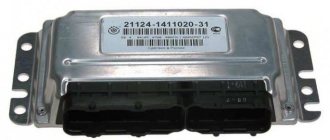
Electronic engine control unit (ECU)
The electronic engine control unit is the brain center of the entire car. All sensors installed in the car are connected specifically to this unit. All necessary calculations and consequences are calculated in the ECU. The engine control unit corrects all its operation. Located at the bottom of the VAZ 2114 dashboard at the feet of the front passenger.
Symptoms of ECU malfunction:
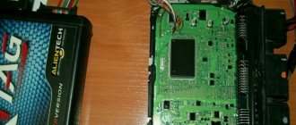
Signs of an ECU malfunction include all of the following signs of sensor malfunctions. After all, each sensor transmits readings to the ECU, and it, in turn, must process them, but it happens that for some reason these processes may not be processed in the ECU. In case of such problems, the ECU must be repaired, the tracks must be soldered, or failed radio components must be replaced.
How to check DPKV
When it is suspected that the crankshaft position sensor is malfunctioning, it is necessary to dismantle the device and inspect it.
Causes and symptoms of sensor malfunction:
- the device body is cracked due to mechanical stress, the core or contacts are damaged;
- due to scuffing of the journal, the opening in the bearing has increased;
- the surface of the components is damaged, scratches or cracks appear;
- the sensitive element has failed over time;
- the crankshaft liners are melted;
- a manufacturing defect appeared;
- the gap between the crankshaft and the liner has increased;
- the working holes wear out or the key is cut off.
Checking the DPKV is performed with a multimeter. The device is capable of measuring the resistance of the core winding. This is done as follows:
- the multimeter switches to the required position, the switch is set to 2 kOhm;
- the contact group is located on the DPKV terminals;
- if the readings are from 500 to 800 Ohms, then the device is working properly;
- to obtain information about inductance, the multimeter is switched to the appropriate mode;
- If the sensor is in perfect order, then we remove the level of about 400 mH.
Often the terminals become dirty or oxidized. They are pre-cleaned with sandpaper. Multimeter readings do not give a 100% guarantee; a dismantled sensor may be faulty and give correct readings only in this form. While driving and the temperature rises, the readings may change. This happens if a short circuit occurs between the turns of the winding. We find the exact inductance and resistance indicators in the device data sheet.
Mass air flow sensor (MAF)
The mass air flow sensor is located in the engine compartment of the VAZ 2114 and is one of the most recognizable car sensors. The mass air flow sensor is attached with two bolts to the air filter box. The mass air flow sensor is responsible for counting the air intake from the engine and transmits the readings to the above-mentioned ECU. The mass air flow sensor is directly related to the formation of the air-fuel mixture.
Signs of a DMRV malfunction:
- Deterioration of car dynamics;
- Increased fuel consumption;
- Floating speed at XX;
- When starting the internal combustion engine, you have to turn the starter for a long time;
Crankshaft position sensor (CPS)
DPKV is installed near the timing belt, namely near the crankshaft gear. This sensor is responsible for counting the crankshaft revolutions from the generator belt pulley. DPKV is involved in the formation of the spark necessary to ignite the fuel mixture in the combustion chamber. If the crankshaft position sensor fails, the car engine will not start.
Signs of DPKV malfunction:
- The car's internal combustion engine does not start;
- Spontaneous stop of the internal combustion engine;
- Uneven operation at idle and high speeds;
Hall sensor replacement
Replacing the Hall sensor will not be particularly difficult. Even a novice car enthusiast can handle this work with his own hands.
The video below shows in some detail the process of replacing the sensor in the distributor of a UAZ car.
Typically, replacing a Hall sensor consists of several steps:
- First of all, the distributor is removed from the car.
- Next, remove the distributor cover and align the timing mechanism mark with the crankshaft mark.
- Having remembered the position of the distributor, you need to unscrew the fasteners with a wrench.
- If there are latches and stoppers, they should also be removed.
- The shaft is pulled out of the distributor.
- All that remains is to disconnect the terminals of the Hall sensor and unscrew it.
- By pulling back the regulator, the faulty part is carefully removed through the gap formed.
- The new Hall sensor is installed in the reverse order.
Checking the functionality of the Hall sensor not only allows you to accurately determine the cause of engine failure. Thanks to simple techniques, the motorist will save his time on repairs and also eliminate unnecessary waste of money.
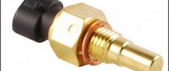
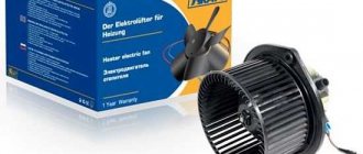
Coolant temperature sensor (DTOZH)
The coolant temperature sensor is installed in the thermostat housing and is used to turn the engine cooling fan on and off. It should be noted that turning on the fan is not the only task of this sensor. DTOZH adjusts the fuel mixture to maintain higher engine speeds when warming up, that is, if the coolant in the car is below operating temperature, the sensor will give readings about the enrichment of the fuel mixture to warm up the engine faster.
Signs of DTOZh malfunction:
- The cooling fan does not work;
- No warm-up speeds;
- The car does not start well;
- Increased fuel consumption;
Throttle Position Sensor (TPS)
The TPS is installed on the throttle itself and is a potentiometer. The sensor will transmit readings to the ECU about the position of the throttle valve. This type of sensor has an unreliable design and quite often fails. On newer VAZ 2114 models with an electronic gas pedal, there is no TPS.
Signs of a malfunction of the TPS:
- High engine speed when warming up;
- Jumps in engine speed;
- Increased fuel consumption;
- Not stable XX;
TPDZ
Electronics are responsible for fuel delivery in the VAZ-2114 car system. Without TPS, the control unit will not be able to determine the optimal time to supply gasoline. Deviations from the correct operation of the TPS lead to an increase in the amount of fuel consumed. The operation of many other car systems depends on the angle at which the remote control is located: cooling, fuel supply.
The TPS is located near the idle speed sensor. In the “fourteenth” system, the work of these two devices is closely linked.
When the TPS breaks down, the car begins to twitch in a certain position of the damper, and instability of engine operation is also noted. All VAZ-2114 8 valve sensors are interconnected in their operation, so two different devices sometimes exhibit the same symptoms of malfunction. If symptoms of a breakdown occur, it is necessary to take a comprehensive approach to checking all controllers.
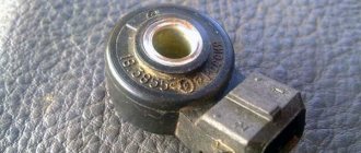
Knock sensor(DD)
The knock sensor is installed on the cylinder block between cylinders 2 and 3. The functions of the sensor are to detect detonation during engine operation and transmit the received signals to the ECU. The sensor is made on the principle of a piezo element and has a simple design.
Signs of DD malfunction:
- High fuel consumption;
- Vibrations during internal combustion engine operation;
- Jerks when moving;
Where are they located?
But knowing about their presence in your VAZ 2114 car is not enough. In case of problems, when the electronic control unit receives incorrect data from signaling devices, they have to be changed.
Whatever one may say, every sensor that has ceased to function properly and transmit correct data on the state of the systems to the electronic control unit must be replaced. Almost all sensors cost no more than a few hundred rubles. But even low cost and small size do not indicate the uselessness of these devices. Change devices promptly.
To do this, you need to understand how to get to this or that sensor. Therefore, we invite you to familiarize yourself with the location of key alarm and measurement devices.
Sensor
Location
On 8 valve engines it is located at the bottom of the valve cover in the cylinder head, and on 16 valve engines it is located on the left end of the camshaft bearing housing
Coolant temperature (engine temperature sensor)
Look for it near the tasty cylinder head cooling jacket pipe
Coolant level
It is located directly on the tank, inside of which there is coolant (antifreeze or antifreeze). Looks like a simple plastic cover that connects to an electrical connector
Brake fluid level
This is a float device located inside the brake fluid reservoir.
Idle speed (IAC)
Look near the throttle valve on the throttle body
Mass air flow
You will find it near the large intake pipe, directly on the air filter housing
Throttle Positions
Located on the throttle body
Crankshaft position (timing sensor)
Its location is near the electric generator drive pulley
Camshaft position (phase sensor)
Near the cylinder head cover, viewed from the air filter side
Oxygen (lambda probe)
Installed in front of the resonator in the intake manifold of the exhaust system
Located between cylinders 2 and 3 near the fan
It should be looked for inside the intake chamber of the fuel tank
Located directly on the gearbox
Look near the cup on the side of the right mudguard. You can get there through the engine compartment
Ambient temperatures
It is installed directly behind the front bumper, exactly in the middle
Each sensor has its own strictly designated place. Having studied their locations, you can easily replace devices in the event of breakdowns or malfunctions.
Some measuring and signaling devices are located literally on the surface, so there is no need to carry out additional dismantling work. To get to others, you will have to seriously dig into your VAZ 2114 and remove quite a few parts.
The integrity of your car, the safety of the driver, passengers and all other road users depend on their performance. Therefore, treat the sensors with appropriate respect, monitor their condition and change them in a timely manner if the need arises.
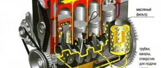
Oil pressure sensor (OPS)
The oil pressure sensor is located near the oil filler neck. The sensor serves as a signal to the driver about a decrease in oil pressure in the engine. When the pressure decreases, it sends a signal to the instrument panel and lights up the low oil pressure warning light.
Signs of DDM malfunction:
- Constant lighting of the oil pressure lamp;
- Oil leakage from the joint in the sensor;
Final inspection of households
To make sure that the DC is fully operational, a diagnostic test should be performed. However, there are several testing options, and each specialist uses either his favorite method or the one that is most effective and easy in a particular situation.
The most common test option is to compare the tester readings with the factory ones. In other words, a multimeter is connected to the DC terminals, and the values on the device are checked. As a rule, if the readings with the DH shutter open are approx. 0.4 V, the sensor is working normally.
Another method is no less popular. It is most often used by car owners who do not carry measuring instruments with them. This method gives the most accurate readings. It is necessary to replace the DC installed in the car with a similar regulator. If the car behaves normally with the new sensor, the engine will not freeze, then the diagnosis has been confirmed - the old DC is no longer suitable.
Some experts recommend diagnosing DH using a simulator. Such a device, often made by hand, is connected to the ignition system. If the spark is supplied normally after this, but before that there was none, the DH is faulty.
To easily replace the DC, you just need to follow the instructions below:
- remove the cover from the distributor;
- turn the crankshaft until the pulley mark coincides with the timing cover mark;
- indicate the position of the distributor rotor (runner);
- dismantle the distributor using appropriate tools;
- remove the pin securing the position of the oil deflector clutch (you can knock it out with a hammer, and pull it out with pliers);
- remove both the coupling and the washer;
- remove the shaft from the distributor body;
- de-energize the DC terminals;
- unscrew the sensor and pull it out through the hole;
- install a new one, assemble everything in reverse order.
Advice. In order for the DC to come out easily, you need to pull back the regulator. This will create a hole through which DH will come out.
It is necessary in order to accurately determine the ignition timing.
It almost never breaks. At the same time, its connectors need to be regularly cleaned of dirt. Usually problems arise due to a break in the wires going to the sensor. Checking is required in situations where a malfunction signal turns on while the engine is running at 3 thousand rpm or more. Installed near the muffler. It determines how much oxygen remains in the exhaust. Its data is necessary in order to properly adjust the fuel supply to the engine. In the presence of oxygen, the proportion of gasoline increases. The computer can only detect complete sensor failure.
Idle air control (IAC)
The IAC is installed on the throttle body of the car and serves to adjust the idle speed by opening and closing the air channels. This sensor is involved in the operation of the internal combustion engine only at idle. It is unreliable and often malfunctions. Subsequently, with the transition to the E-GAZ system, the idle air control was removed.
Signs of IAC malfunction:
- The internal combustion engine stalls at idle;
- High speed at idle;
- High fuel consumption;
We find and fix the problem
Signs of DMRV problems
So:
- The engine does not start;
- Unstable engine operation at idle;
- Engine idle speed is too high or too low;
- “Failures” during acceleration and poor vehicle dynamics;
- Fuel consumption is significantly exceeded.
Diagnostics
In addition to the above symptoms, a malfunction of the flow meter can be detected by the electronic control unit, namely its diagnostic system, which will issue a “CHECK” signal on the instrument panel. Unfortunately, without specialized diagnostic equipment with a 100% guarantee, it is impossible to identify a malfunction of the mass air flow sensor by reading error codes; you will have to contact a service station. Although, this is also controversial advice, since they will most likely offer you to identify the malfunction of the flow meter by replacing it with a known good device, but you can do this with your own hands without outside help. Let’s try to identify a flow meter breakdown in “field” conditions using four methods known to mankind. In general, we read carefully and remember. So, instructions:
The first method is the main one.
We disconnect the wire plug from the sensor and start the engine, the engine speed will rise to at least one and a half thousand per minute, and we’ll move off. If the car has acquired agility that is unusual for it, there is a malfunction of the sensor. Let me explain: the sensor is disabled, which means the ECU supplies the amount of gasoline according to the throttle position (emergency mode), without taking into account the signal from the flow meter.
When replacing the firmware in the ECU, no one will be able to say exactly what the idle speed setting is during emergency operation (method one). Therefore, this nuance is checked as follows: we slip a feeler gauge one millimeter thick under the throttle valve stop. After the speed rises, disconnect the sensor wire connector. The engine stalled - the firmware is to blame, or rather the idle speed adjustment in emergency mode.
The third method is the most accurate.
We turn the tester into DC voltage measurement mode and set the limit to two volts. We connect the probes to the yellow output wire - the plus probe and to the mass colored green wire - the minus probe, located relative to the windshield - the first and third, respectively.
Turn on the ignition, do not start the engine, take readings:
As a rule, the voltage of a working sensor is 0.996 – 1.01
Volt, but during wear it steadily increases:
- the sensor is in good condition at voltages from 1.01 to 1.02 V;
- slight wear: 1.02 – 1.03 V;
- decent mileage, will soon require replacement: 1.03 – 1.04 V;
- to be replaced at 1.04-1.05;
- It is prohibited to operate the sensor at a voltage of 1.05 Volts or higher.
Method number three
Method four, visual.
Using a curved screwdriver, remove the corrugated air duct going to the throttle assembly, and carefully inspect the internal surfaces of the air duct and sensor for the presence of condensate and oil; they should be dry and clean.
Using a ten key, unscrew the two screws and remove the sensitive element.
Checking the O-ring
As can be seen in the photo, on its front part there is a rubber sealing ring that prevents the leakage of foreign air into the intake manifold in addition to the sensor
Please note that when the integrity of the ring is destroyed, a small layer of dust forms on the sensor mesh. This is also one of the main reasons for “killing” the flow meter
In addition to the above methods, it is necessary to mention such factors as the lack of on-board power supply and unqualified maintenance (even innocent wiping of the working surfaces with a cotton swab can lead to damage to the unit). This unit is considered non-maintainable and non-repairable.
Phase sensor (PF)
The phase sensor is located:
- In 16-valve engines near the intake camshaft gear;
- In 8-valve engines from the end of the cylinder head near the mass air flow sensor;
Serves for phased fuel injection. It is a fairly reliable sensor that rarely fails. The design of the sensors for 8 and 16 valve engines is different and is not interchangeable.
Signs of DF malfunction:
- Increased fuel consumption;
- Engine vibrations;
Signs of DF malfunction
If you notice the following signs, then the DF has failed: When starting the engine, you noticed that the starter spins for 4 seconds and the check engine light is on. In this case, the ECU waits for readings from the DF, does not wait and relies on the system (according to the DPKV) Failures in the self-diagnosis mode Increased gasoline consumption Reduced engine dynamics DF error If the DF malfunctions, a check light comes on, which means error P0340 - “DF error” or “camshaft position sensor” faulty." But as mentioned earlier, the description of the problem is different, but the essence is the same: the DF and the camshaft position sensor are the same unit.
Brake pedal sensor
The brake pedal sensor is installed on cars to turn on the brake lights (brake lights) when the car brakes. In cars with the E-GAZ system, the brake pedal sensor is also connected to the ECU and participates in the operation of the gas pedal to distribute the engine load more evenly.
Signs of malfunction:
- Gas pedal failure;
- Jerks when moving;
- Loss of car dynamics and power;
Speed sensor (DS)
The speed sensor is installed in the gearbox housing near the exhaust manifold. Designed to calculate the vehicle speed and adjust the speed when driving in neutral gear.
Signs of DS malfunction:
- Increased fuel consumption;
- Lack of travel speed XX;
- Dips when pressing the gas pedal sharply;
- Speedometer malfunction;
What is the Hall effect
It lies in the fact that during the interaction of magnetic and electric fields, when the electric field flows in a certain way through the magnetic field in which the semiconductor wafer is located, a potential difference appears on it, the so-called Hall voltage.
This effect has gained practical application in DS because when moving, this voltage is converted into a pulse-frequency signal, which is transmitted to the controller. The higher the speed, the higher the frequency of the signal. It is calculated that the DS emits 6004 pulses per kilometer of travel. Based on the interval between these pulses, the controller calculates the speed of the machine.
Oxygen sensor (DC, lambda probe)
An oxygen sensor, also known as a lambda probe, is installed in the exhaust manifold and is designed to record exhaust carbon dioxide gases. In some car models that were produced after 2010. There are 2 oxygen sensors. Serves to adjust the air-fuel mixture based on carbon dioxide measurements.
Signs of DC malfunction:
- High fuel consumption;
- Loss of engine power;
- Difficult starting of the internal combustion engine;
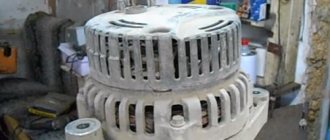
Ignition module (IZ)
The ignition module is installed on 8-valve engines on a platform that is attached to the cylinder block. The 16-valve VAZ 2114 engines use individual ignition coils. The module is designed to generate a powerful high-voltage spark necessary to ignite the air-fuel mixture in the combustion chamber of a car. It has two coils each, of which is responsible for two cylinders. If one of the coils fails, 2 cylinders stop working at once.
Signs of malfunction of the MH:
- Several cylinders do not work (most often two);
- High fuel consumption;
- Engine vibrations;
- Loss of power and traction;