VAZ 2110 2111 2112 (injector) fuses and relays
VAZ 2110 2111 2112 (Lada 110 111 112) - a family of cars produced in 1995, 1996, 1997, 1998, 1999, 2000, 2001, 2002, 2003, 2004, 2005, 2006, 2007, 2008 and 2009 with sedan and hatchback bodies and a station wagon mainly with 8 and 16 valve gasoline engines ( injector , carburetor). In this article you will find a description of the fuse and relay blocks of the VAZ 2110 2111 2112 with diagrams , photographs and their locations. Electrical connection diagram. Let's highlight the fuse responsible for the cigarette lighter.
The purpose of fuses and relays in your VAZ 2110 (2111 / 2112) relay may differ from those presented and depend on the year of manufacture. The current purpose can be printed on the block itself.
Latest news about Lada Vesta Cross
Nowadays, AvtoVAZ produces cars of a completely different level of comfort and reliability, just like the Lada Vesta car model range: modern appearance of the sedan, a variety of body colors, a variety of configuration options, a thoughtful interior and modern electronics. If over the course of several years they have managed to get used to the sedan, then many people are looking forward to the Lada Vesta Cross model and are monitoring the emergence of new information.
Help, fuses are constantly burning. What is the reason?
- How to install a remote fuse for the stove in 2110? – 2 answers
- The engine stalls when driving 2110 - 2 answers
- Electrical equipment failed in VAZ 2110 - 2 answers
- Turn signals and emergency lights do not light up on VAZ 2110 - 2 answers
- Where are the fuses for the VAZ 2110? – 1 answer
Well, there could be quite a few reasons. To begin with, it would be nice to find out which one is burning. If you don’t know, the VAZ 2110 fuse diagram will help. And so.
Possibly a bad contact in the fuse box is to blame; it needs to be tightened.
Maybe there is a short circuit somewhere in the wiring or moisture gets in, then you need to call and look for the unfortunate place.
Another reason may be that one preload is loaded with many electricity consumers, and it cannot cope with the load.
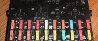
Main unit
The main block with fuses and relays is located in the cabin, on the left side, under the control panel. To access, press the latch switch.
Photo - diagram Option 1
Scheme Option 2
Scheme Option 3
Description of fuses
p, blockquote 15,0,0,0,0 —>
| F1 | 5A Lamps for license plate lights. Instrument lighting lamps. Side light indicator lamp. Trunk light. Left side marker lamps |
| F2 | 7.5A Left headlight (low beam) |
| F3 | 10A Left headlight (high beam) |
| F4 | 10A Right fog lamp |
| F5 | 30A Electric motors for glass door lifts |
| F6 | 15A Portable lamp |
| F7 | 20A Electric motor of the engine cooling system fan. Sound signal |
| F8 | 20A Rear window heating element. Relay (contacts) for turning on the heated rear window |
| F9 | 20A Recirculation valve. Windshield, rear window and headlight cleaners and washers. Relay (coil) for turning on the rear window heating |
| F10 | 20A Reserve |
| F11 | 5A Starboard side marker lamps |
| F12 | 7.5A Right headlight (low beam) |
| F13 | 10A Right headlight (high beam). High beam warning lamp |
| F14 | 10A Left fog lamp |
| F15 | 20A Electric seat heating. Trunk lock lock |
| F16 | 10A Relay - turn signal and hazard warning light switch (in hazard warning mode). Hazard warning lamp |
| F17 | 7.5A Interior lighting lamp. Individual backlight lamp. Ignition switch illumination lamp. Stop lamps. Clock (or trip computer) |
| F18 | 25A Glove box lighting lamp. Heater controller. Cigarette lighter. |
| F19 | 10A Door locking. Relay for monitoring the health of brake light lamps and side lights. Direction indicators with warning lamps. Reversing lamps. Generator excitation winding. On-board control system display unit. Instrument cluster. Clock (or trip computer) |
| F20 | 7.5A Rear fog lamps |
Fuse number 18 at 25A is responsible for the operation of the cigarette lighter.
The fog lamp fuse is installed separately in the instrument panel niche behind the main unit.
Relay purpose
p, blockquote 19,0,0,0,0 —>
- K1 - lamp health monitoring relay
- K2 - windshield wiper relay
- KZ - relay-breaker for direction indicators and hazard warning lights
- K4 - relay for low beam headlights
- K5 - headlight high beam relay
- K6 - additional relay
- K7 - rear window heating relay
- K8 - rear fog lamp relay
Electrical diagram of the block
Tips for tuning VAZ cars and more.
In order for us to decide what will provide alternative power to the power windows. Let's study the standard electrical circuit diagram of the operation of window regulators (Fig. 1).
It shows that power is provided only after the ignition switch is turned on and the additional relay K6 (not indicated in this diagram) and the power window relay (position 11) are activated, which power the power windows through their contacts and fuse F5 (30A). We will provide power to the power windows through the cigarette lighter circuit. To do this, it is best to dismantle the lower left plastic panel near the floor in the passenger’s feet and attach a wire to the cigarette lighter connector. The connection is made with a red-blue wire - this is the “+” contact. (the connection to this wire in the diagram is shown with a black wire)
This is interesting: What is the best carburetor cleaner?
Next, stretch this wire in a plastic box between the front seats, bring it to the power window button blocks and connect it to the white-black wire. (common + for all 4 window regulators) In this case, remove fuse F5 from the mounting block to limit the current through it to other energy consumption systems. That is, do not allow alternative power supply to consumers of the on-board network, as well as power windows through the power supply of the cigarette lighter. In this case, the cigarette lighter fuse should be replaced from 15 A to 30 A, since the rating for the power window fuse is higher than that of the cigarette lighter.
Some misconceptions. A jumper in the power window relay block will do nothing for their independent operation. Since before this relay there is still an additional relay K6 which limits the power to the power window relay. But it is prohibited to install a jumper in relay K6 to supply voltage to the power window relay, since it powers not only the power windows but also other systems.
After this modification, the power windows will operate directly from the car’s battery and will not require turning on the car’s ignition to activate them.
Additional block
It is located under the center console and is covered with a lid. One part is accessible from the right side.
Designation
p, blockquote 27,0,0,0,0 —>
- 15A - Ignition module, controller
- 15A - Canister purge valve, vehicle speed sensor, oxygen concentration sensor (heating), air flow sensor
- 15A - fuel pump, fuel pump fuse, injectors
- Electric fan relay
- Fuel pump relay
- Main relay (ignition relay)
The other part is on the left side of the console:
Decoding
p, blockquote 31,0,0,0,0 —>
- Central locking control unit
- Immobilizer block
- Relay for turning on rear fog lights.
On our channel we also prepared a video on this publication. Watch and subscribe.
Guides
- Car manuals, instructions, repair and operation manuals for cars 55 views
- BMW error codes 48 views
- Mercedes error codes 47 views
- VW Car Repair and Operation Manual 30 views
- Location of diagnostic OBD connector in FORD 29 views
- Toyota car repair and operation manual 27 views
- Repair and operation manual for Fiat cars 25 views
- Fuse and relay block Citroen Jumper, Fiat Ducato, Peugeot Boxer from 2006 to 2014 25 views
- Fuse and relay box Honda Civic from 2006 to 2011 24 views
- Mercedes car repair and operation manual 24 views
Scheme on ten
The fuse box diagram for a VAZ 2110 with an 8- and 16-valve injector is identical. The descriptions below will be relevant for owners of both engine types.
Main MB
First, it is worth considering the area with the VAZ 2110 relay. In the diagram they are indicated by the letter “K”:
- Regulates the operation of all lamps.
- Controls the electric windshield wiper.
- Special purpose device. Controls the operation of lamps when the emergency alarm system is turned on.
- Low beam switch.
- High beam control.
- A backup device required to connect additional devices.
- Electric heated rear window.
Under the relay part there is a battery of protection, where each is responsible for a specific section of the circuit. In general, you can understand their designations using pictograms.
The safety battery is designated by the letter "F":
- Responsible for the lighting set: number, dimensions on the dashboard, left clearance, trunk.
- Near lighting.
- Distant lighting.
- Right fog lights.
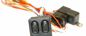
- Electric windows.
- Fuse for cigarette lighter and portable lamp.
- Radiator cooling and horn.
- Heated glass.
- Cleaning and washing system.
- Spare.
- Right side lights.
- Low beams of the right headlight.
- Far right headlights.
- Left fog light.
- Heated seats.
- Hazard warning lights and turn signals.
- Brake light protection, rear lock and interior lighting.
- Another 1 fuse for the cigarette lighter for the VAZ 2110, for the glove box and heater lights.
- Rear lights, as well as monitoring the performance of the brake light.
- Rear fog lights.
The MB also contains numberings F21, 22 and 23. Moreover, they are located in the relay battery. They are reserve and do not participate in the main work.
As you can see, almost all electrical circuits are protected by a specific safety device. They are not installed only in the battery charging system (the battery and charging have their own protection). Each of them has its own rated current, as can be seen in the photo above.
In case of necessary repairs, first check the protection battery. For example, the right fog lights burned out, and replacing the light bulb does not help. In this case, it is enough to find the number in the list (in this case, 4) and call it. If it is “dead”, all that remains is to replace it and check its functionality again.
Please note that they are all fusible, that is, if there is an overcurrent they melt and break the circuit. Replacing them with any others is strictly prohibited. As well as installing protection with a different ampere limitation or changing the location of the fuses.
First additional MB
Directly behind the main MB there is an additional one. There are only 3 safety and relay devices installed there, located next to each other.
The relay and fuse locations are as follows (from left to right):
- The 1st controls the ignition and control module of the car.
- The 2nd serves air flow, heating and speed sensors.
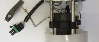
- The 3rd fuse protects the fuel pump on the VAZ 2110. By the way, it is this that is often responsible for fuel failure. If it breaks, check it first.
The relay part has the following purpose:
- Relay number 4 controls fan switching.
- Number 5 is the fuel pump.
- Relay 6 controls the ignition system.
Cigarette lighter diagnostics and repair
If after replacing the protective element the element does not start working, then the reason must be looked for elsewhere. It is not always necessary to install a new device; you can repair the cigarette lighter. First of all, you need to check the wiring that goes from the network to the socket. You should test the wires with a multitester. If there is no power during diagnostics, this indicates a broken wire. Repairs will require new parts, rosin, tin and a soldering iron.
The second malfunction, which does not require a complete replacement of the cigarette lighter, is the breakdown of the mica fuse, which is located inside the device. To do this, you need to disassemble the socket of the socket and find a small mica semiconductor (it may melt). It is dismantled, replaced with a new one, after which everything is put back together and the functionality of the device is checked.
How to remove the cigarette lighter of a VAZ-2110
To remove the cigarette lighter on a VAZ, you need:
- Open the hood. Then remove the negative cable from the battery and take out fuse F18.
- Unscrew the fasteners and remove the 2 parts of the cladding.
- Pull out the three-pin plug.
- Remove the trim under the handbrake and the cover from the gearbox.
- Move the seats back, unscrew the tunnel fasteners and pull out the cartridge.
- Pry the cigarette lighter latch and remove the socket for repair.
Connecting a new
The cigarette lighter is connected in the reverse way:
- A working device is installed.
- The facing casing of the gearshift lever and handbrake is mounted in place.
- A three-pin plug is connected.
- Then you need to connect to power.
- Check the correct connection and functionality of the cigarette lighter.
Pinout
The layout of the elements is as follows:
- The red wire is responsible for the plus and is connected to the device through fuse No. 18. It is capable of passing a current of no more than 25 A. Exceeding it leads to burnout of the wire.
- The yellow cable in the pinout is also a plus and will be used to highlight the part.
- The black wire responsible for power is negative. One end goes to the device, and the other to the battery.
MB types
It is worth noting that the pinout of fuses for the VAZ “Ten” is somewhat different, depending on the revision. The location of the backup protection relay varies greatly.
Version 3722010
Version 3722010 01
Version 3722010 08
The article was written with the support of our partners in Minsk - unishop.by. Here you can buy household dehumidifiers of various types, of excellent quality and at a reasonable price. unishop.by is a large shopping portal where you can find the right product at a good price, easier and faster.
Source
Functions
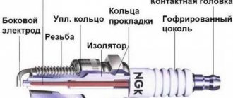
A blade-type fuse is a wire designed to carry a certain amount of current. If the parameter is exceeded, part of the element is heated and melted, which allows the power circuit to be broken.
To install the part in the mounting block, flat rectangular legs are used, which are clamped with spring contacts. Metal parts are placed in a plastic case; the color of the material depends on the product rating. The body is transparent, which allows you to visually assess the condition of the fuse thread.
How to use the fuse diagram on a VAZ-2110 when repairing a car?
The fuse diagram for the VAZ-2110 is a step-by-step block diagram depicted in pictures, in which all the elements of the electrical equipment of the car are marked, which are responsible for protecting the car from fire in the event of unstable operation of one of the systems. In general, on a car of any VAZ model there are 3 special blocks located alternately, where fuses and a small relay are attached. Features of their location are indicated in the diagram below.
The exact location of each fuse box in the VAZ-2110
Signs of faulty fuses
- The module has changed color, black dots are visible on the surface, carbon deposits,
- On the instrument panel (European panel) an indicator indicates a malfunction in the engine compartment,
- When the engine is running, the ignition is on, the battery is charged, some mechanisms do not work, they do not work correctly,
- In the car interior you can hear the smell of burning, melted in the area where the mounting block is located,
- The modules feel hot to the touch.
This is interesting: What kind of drilling for a Volkswagen Polo
How are the blocks separated in the machine?
The main type of block is placed in the most convenient place for the driver. In this version of the VAZ it is located on the left side of the body directly at the steering wheel. Easy access to the unit is provided using a built-in button located next to the car's headlight control.
2 backup units with relays are located separately in the right and central parts of the console just behind the dashboard. One of the fuses shown below in the diagram will be located at a distance from the rest of the list - it can be found in a special compartment behind the main fuse block, next to the mounting block. To timely repair electrical equipment on a VAZ-2110, you need to learn how to quickly determine the location of a blown fuse, and also know which elements of the car its failure will affect.
Advice: very often one burnt valve can lead to replacing the vacuum booster on a VAZ-2110. That is why it is important to check not only the general condition of the fuse, but also the parts that interact with it, for example, the injector.
Wiring and other possible causes of failure
The most common reasons why the cigarette lighter does not work are the following:
- spent protective element;
- mica semiconductor melts;
- regular overload of the device (connecting too powerful devices to the outlet);
- poor contacts and wandering short circuit;
- old wiring;
- burnout of the thermal coil.
If fuses numbered 6, 8 or 18 begin to fail frequently, the cause may be worn wires or a stray short circuit. First of all, you need to inspect the three-pin connector, and then the rest of the wires. They should not have creases, burnt areas, abrasions or tears. The reason may be the presence of rust and oxidized elements. To fix it, just pull out the device and clean the contacts.
If the coil burns out, the fuse may remain operational, but the cigarette lighter will no longer perform its functions. The fault cannot be repaired; a complete replacement of the device is required.
- The best all-season tires for passenger cars
- What is better Methane or Propane for cars
- Which studded tires are best to buy for the winter?
- Where is the VAZ 2115 cigarette lighter fuse located?
What does the relay kit with fuse box do?
Layout of fuses and relays in the main mounting block of the VAZ-2110
The above diagram describes the location of the main relay kit and fuse box. The following elements are located here:
- K1 is a type of relay responsible for monitoring the health of a set of light bulbs;
- K2 – this component is associated with the operation of the front pair of wipers;
- K3 – behind this designation lies a breaker relay that regulates the operation of the repeater and the vehicle’s alarm sign;
- K4 and K5 – a pair of relays for the injector, which is responsible for turning on the low/high beam headlights of the VAZ-2110;
- K6 - an additional type of relay required to replace one of the burned out ones from the main unit;
- K7 - this element is responsible for turning on the heating function on the rear window;
- K8 - like K6, is a backup relay.
Tip: If you notice the main signs of a malfunctioning oxygen sensor, you should first look at the fuses. If everything is in order in the mounting block, then you should seek help from a car service for diagnostics.
Video with reasons for fuse failure
There are additional faults that can cause the device to break down. These include.
- Bad contacts. Over time or heavy use, the connection inside the cigarette lighter may become loose. Incorrect connection of devices leads to loose sockets and poor contact. This can be treated by bending the metal tendrils on the cartridge or by resoldering.
- With age, oxides or rust appear on the cigarette lighter, which has a bad effect on its operation. The situation can be corrected by treating the contact areas with a needle file. It is necessary to clean them and remove all traces of corrosion on the cigarette lighter. Another malfunction of the cigarette lighter on a VAZ is a burnt-out nichrome spiral. It is recommended to replace the device here.
Due to these factors, the protective element can also burn out. The video below will help you figure out where the fuse is located and how to repair the VAZ 2110 cigarette lighter.
What does the second set of fuse boxes do?
The symbols F1-F20 indicated below in the electrical diagram are the elements that characterize the set of fuses. The electrical circuit in a VAZ-2110 car is protected using fuses based on the specific calculation of the model for the rated current value specified upon purchase.
At the same time, fuses are not responsible for the quality operation of the circuit consisting of a sample battery, a separate type of generator circuit, the ignition system and engine valve starting. To replace a faulty fuse in this mounting block, follow the following plan:
- Find a fuse that has mechanical damage or its body has burned out;
- According to the instructions, determine and eliminate the reason why it turned out to be faulty;
- Install a new fuse using the backup model.
Tip: Never try to replace a fuse with special jumpers. In the future, this will lead to failure of those devices that are assigned to this fuse.
Diagram with designations for the second set of fuses in the block
Standard version of the brake light operating diagram
Power is supplied to fuse F17 from the battery, then the current goes to limit switch contact 11, and then, if the limit switch is closed, a circuit is formed with the filament of lamps 7. But note: part of the circuit is relay K1, more precisely, its contacts 5 and 4.
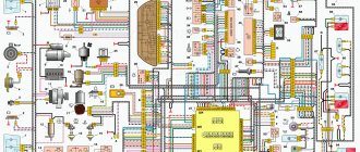
Basic network diagram
A complete electrical diagram with explanations of the VAZ-2112 car is here.
If the brake lights do not light up, on the VAZ-2112, as on all Tens, check one fuse. It is called F17 and is located in the mounting block to the left of the driver.
Main mounting block
It is important to know: voltage is always present at one of the fuse terminals. Check it out!
A few words about the “serviceability relay”
The lamp health relay is called K1, and it is the largest in the mounting block. If you remove this relay, then when you press the pedal you can dial the voltage at terminal 5 (but not 4). Look at the diagram again, and it will become clear what we are talking about.
The largest relay in the block
All relay contacts are numbered. Check the voltage at the block terminals:
- 6 – “mass” potential;
- 2 – voltage “+12”, but only after turning on the ignition;
- 5 – “+12” by pressing the pedal;
- 4 – the terminal rings like a ground tap.
If the potential “0” is not generated at terminal “4,” it means that the lamp filaments are burnt out or there is a break in the wiring. Now consider something else: the ground potential has been detected, but the lamps do not light. This is where suspicions of a short circuit arise.
Location
Since AvtoVAZ engineers tried to do everything so that car owners would not have problems replacing relays and fuses, it would be stupid to come up with a clever arrangement. Therefore, finding them is not difficult.
- The main unit is located to the left of the steering wheel;
- You will find the first additional block in the dashboard inside the niche, directly behind the main mounting block;
- The second additional block is located in the same place, only on the opposite side.
We will get acquainted with each block separately so that you do not have any confusion when searching for one or another fuse.
On injection engines with 16 and 8 valves, the location of the MB is identical, so the instructions are equally relevant for owners of both versions of the dozen.
Main MB
Relays and fuses are located here. Let's look at their descriptions in more detail and separately.
Found the main MB
Let's start with the relay.
| Designation | What is he responsible for? |
| K1 | Car lamp operation |
| K2 | Electric windshield wipers |
| K3 | Special relay that interrupts the turning lights when the hazard warning lights are activated |
| K4 | Turning on the low beam |
| K5 | Turning on the high beam |
| K6 | Area for installation of additional device |
| K7 | Rear window heating operation |
Fuse diagram
Next comes the fuses. They are located in the same place, but are designated by the letters F.
Each fuse is indicated with a current rating and designation. This allows you to use a new fuse with parameters that meet the requirements of the equipment connected to it.
| Designation | Rated current | What is he responsible for? |
| F1 | 5A | Lamps for license plate illumination, instrument panel illumination, indicator lights on the instrument panel, left side position lights, luggage compartment illumination |
| F2 | 7.5A | Low beam left headlight |
| F3 | 10A | Left high beam |
| F4 | 10A | Right front fog lamp |
| F5 | 30A | Electric door windows |
| F6 | 15A | Carrying lamp, cigarette lighter |
| F7 | 20A | Radiator fan, horn (horn) |
| F8 | 20A | Heated rear window |
| F9 | 20A | Windshield wipers and washer |
| F10 | 20A | Backup fuse |
| F11 | 5A | Right dimensions |
| F12 | 7.5A | Low beams in the right headlight |
| F13 | 10A | High beams in the right headlight |
| F14 | 10A | Left fog lamp |
| F15 | 20A | Heated seats in the cabin |
| F16 | 10A | Hazard signal, turn signals |
| F17 | 7.5A | Stop signal, ignition switch illumination, interior lighting |
| F18 | 25A | Interior heater, glove compartment light, cigarette lighter |
| F19 | 10A | Reversing light, brake light monitoring |
| F20 | 7.5A | Rear fog lights |
First additional block
Inside the central panel there is the first of two additional blocks provided for the VAZ 2110. You can find it at the bottom left on the front passenger side.
This block provides three fuses. Each of them has the same power rating - 15A.
- The first fuse is responsible for your vehicle's ignition and controller module.
- The second protects the mass air flow sensor, heating sensor, speed sensor and purge valve.
- The third is necessary to ensure protection of the injectors, as well as the fuel pump. So if problems arise with the fuel pump, the first thing we recommend is to check the condition of the fuse responsible for it.
Location of the additional block
Plus, the same block includes three relays:
- Relay number 4 is responsible for the electric fan;
- Relay number five is the electric fuel pump;
- The third relay is part of the ignition protection group on your VAZ 2110.
Second additional block
The second additional block should be looked for already in the driver’s feet, on the right. Behind the protective cover on the console you will find the required board.
There are three more components on it. They are responsible for:
- Immobilizer operation;
- Additional optics (mostly fog lights);
- For the operation of the car's central locking control.
Replacing the cigarette lighter fuse
It would seem that what’s wrong with replacing the fuse, I pulled it out and inserted a new one. But no. Here is the correct procedure for replacing a fuse:
- Turn off the car ignition.
- Disconnect the ground from the car battery.
- Carefully remove the blown fuse using special pliers. If they are not there, then use pliers (pliers).
- The new fuse must be installed so that it is designed for the same current strength that was on the old blown fuse. For example, on the PCB it says 20, which means that it can withstand up to 20 Amperes. If you install a more powerful one, then the fuse will be able to withstand load surges, but the cigarette lighter itself may burn out. The fuse can be inserted from either side.
- An old burnt-out fuse will have a burnt-out thread; you can look and find out whether it is the cause of the cigarette lighter failure. It also happens that the cause may not be a PP, but a broken wire. If the fuse is intact, you need to test the wiring with a multimeter.
- Close the block cover.
- We connect the disconnected negative wire back to the battery terminal.
- Turn on the ignition and check the functionality of the cigarette lighter.
Where is
The fuses located in the instrument panel to the left of the steering column casing are responsible for protecting the power circuits on VAZ-2110 cars. The top of the unit is closed with a decorative cover, which is secured with a spring clip. To access the fusible links and relays, you need to press the button located under the rotary control for the headlight range control. The decorative casing folds down along with the mounting plate and the protective and distribution devices. On VAZ-2112 and 2111 cars, blocks are used that differ in the number and location of the relays.
Also inside the mounting block are special plastic tweezers and spare inserts. To replace the fuse, the part should be grabbed tightly with tweezers and then carefully pulled out of the socket. The new part must have an identical value; the use of homemade inserts made of wire or foil is strictly prohibited.
The use of fuses designed for high current strength is not allowed, as this may cause the wiring to heat up and the vehicle to catch fire.
Since the cars of the “tenth” family were not equipped with a standard head unit, the installation of radio tape recorders was carried out at dealership centers or by the owners themselves. Since the head acoustic device is a consumer of electric current up to 10-15 A, it is switched through the most powerful fuse. In most cases, this was done using a fuse link designed to protect the cigarette lighter circuit and heater controller. The device has a rating of 25 A, located in the bottom row in the third position from the right.
This switching scheme speeds up installation, but is not correct, since there is a risk of overloading the radio or burning out the insert due to the simultaneously operating head unit and cigarette lighter. It is recommended to connect the radio directly to the battery; a 10-15 A fuse is located inside the power cable.
To protect the battery from discharge, the circuit passes through the ignition switch; a cord with red insulation is used for switching.
When the engine is turned off, the radio does not work, but voltage is supplied (through a yellow insulated cable) to save the settings.
The head unit contains a blade-type fuse rated at 5-15 A (depending on the equipment modification). The element is placed either next to the ISO standard connection block, or inside the wiring harness that comes with the radio. To replace an element, you need a player from a standard socket; for this, special hooks are used that press out the spring clamps.
After installing a new element, it is recommended to check the functionality of all devices involved in the circuit section. If the fuse blows again, the cause of the malfunction is a short circuit in the electrical wiring or inside the head unit. A tester is used to check the condition of the wires; it is recommended to send the radio to a service center for diagnostics and repair.
Functions
The fuse of the radio, located in the power circuit, is designed to protect the electronic components of the equipment from the consequences of short circuits. The device is a thin thread of low-melting metal, designed to carry a certain current value. As the value increases, the element heats up and subsequently melts. The process takes place in a short time, which allows you to maintain the player’s electronics and the insulation of power cables in good condition.
The thread is soldered to the legs, all elements are housed in a transparent plastic case. The color of the plastic allows you to determine the rating of the fuse link; the digital value is applied to the end part with white or black paint. A fuse of this type is called a blade fuse and is installed in the mounting block in spring contacts that protect the product from falling out.