The principle of operation of the braking system
The operation of a hydraulic drive is based on the property of a liquid not to be compressed by external influences. Thanks to this, the liquid perfectly performs the role of a force transmitter without any losses, but provided that there is no gas in its composition.
The principle of operation of a hydraulic brake system is very simple: the driver presses the brake pedal, thereby beginning to act on the brake fluid located in sealed pipelines. Since it does not compress, the force leads to its movement through pipelines, the ends of which are connected to working mechanisms. Because of this, the pressure in the cavities of the mechanisms increases, and the pistons of the mechanisms come out of their seats, pressing the pads against the discs or drums - the movement slows down. When you stop pressing the pedal, the pressure drops (the fluid returns) and the pistons of the mechanisms return to their original position.
Video: How the braking system works
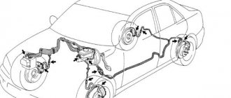
2110 brake design
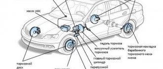
A dual-circuit hydraulic system with a vacuum brake booster is not uncommon on cars developed in the 80s. Easy to maintain, without unnecessary electronic bells and whistles, like ABS, cheap spare parts and pads. The front brakes are disc, and on models 2112, in the hatchback body, they are also ventilated with a larger diameter. This is because on the twelfth only 16-valve engines were installed and more effective brakes were needed to stop this incredible hundred-horsepower power. And also in order to cope with the Opel engine of 150 horsepower, which was also sometimes used for modification by dozens.
The rear brakes are tens of drum type, and the parking brake is mechanical. Everything is like in the good old classics. The car has a vacuum brake booster and the system is divided into two circuits. If one of them fails, the second one remains operational, so there won’t be a dozen left without brakes. The circuits work in a diagonal pattern - front-rear wheel diagonally. Also, the brake system of the VAZ 2110, the diagram of which is presented above, has a pressure regulator for uniform distribution of braking force, depending on the load of the rear axle. Both brake circuits are connected through the regulator.
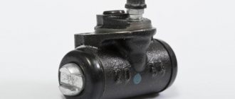
Master brake cylinder. Purpose, device
The main element of the hydraulic drive is the brake master cylinder (MBC). It is thanks to him that the mechanical action is converted into brake fluid pressure. It also separates the entire braking system along its contours, which is very important.
The main condition for the normal functioning of the hydraulic drive is the tightness of the system. If the pipelines break down due to a leak, the entire system will stop working. To avoid a complete failure of the system, it was divided into two circuits independent of each other. Each of them combines two brake mechanisms. As a result, if the pipeline of one of the circuits is damaged, the second remains sealed and the mechanisms to which it is connected continue to perform their function. And although the efficiency of the system decreases, the car still retains the ability to brake.
The design and operating principle of a dual-circuit gas turbine engine are quite interesting. And although they may differ in appearance, the internal structure of all main cylinders is almost the same.
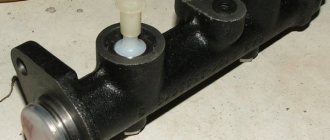
There is a cavity made inside the body and channels for connection with pipelines (leading to the brake mechanisms) and a reservoir from where fluid is supplied. In this cavity there are two pistons installed one behind the other. They act on the liquid. To ensure that the pistons return to their original position after the pedal is released, they are both spring-loaded. Moreover, the spring stop of the first piston is the second one. The spring of the second piston rests against the end wall of the housing cavity.
Since each of the pistons is responsible for supplying liquid only to its own circuit, the entire cavity is divided into two chambers (one is located between the pistons, the second is between the piston and the housing wall). To ensure the tightness of each of them, rubber sealing elements are installed on the pistons.
Each of the working chambers is connected to the tank by two channels - compensation and bypass. Thanks to them, the amount of fluid in the system is replenished and the formation of vacuum and air in the system is prevented when the pedal is released. Also, two pipelines are connected to the chamber, each of which leads to its own brake mechanism.
Video: Brake master cylinder
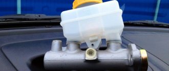
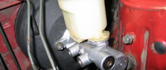
The tank can be attached directly to the GTZ body or be remote (in this case it is connected to the cylinder by pipelines). The liquid from it is supplied to both circuits, but there is a partition inside the tank that separates the liquid between the circuits. This is necessary so that in the event of a depressurization of the system, all the liquid does not leak out.
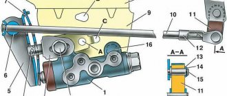
Master cylinder with reservoir
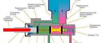
1 – main cylinder body;
2 – low pressure sealing ring; 3 – drive piston of the “left front–right rear brake” circuit; 4 – spacer ring; 5 – high pressure sealing ring; 6 – pressure spring of the sealing ring; 7 – spring plate; 8 – piston return spring; 9 – washer; 10 – locking screw; 11 – drive piston of the “right front–left rear brake” circuit; 12 – connecting sleeve; 13 – tank; 14 – brake fluid emergency level sensor; A – clearance Master cylinder with sequential arrangement of pistons. A tank 13 is mounted on the master cylinder body, in the filler neck of which a sensor 14 for emergency brake fluid level is installed. The high pressure O-rings 5 and the rear wheel cylinder rings are interchangeable.
Principle of operation
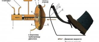
Now let's look at how it all works: due to the action of springs, the pistons are set in their original position. In this case, the compensation channels are open, the chambers are completely filled with liquid (the system is connected to the atmosphere).
When the driver presses the brake pedal, the rod connected to it moves. This rod, overcoming the force of the spring, pushes the first piston. As it moves, it closes the compensation channel, which leads to sealing of the circuit (it is disconnected from the atmosphere) and opens the bypass (liquid from the tank enters the cavity behind the piston). At the same time, the pressure in the chamber begins to increase. One part of the liquid from it goes into the pipelines, acting on the brake mechanisms, while the other pushes the second piston. While moving, it does the same thing as the first one - it closes one channel and opens another, and also pushes liquid into the pipelines.
When the pedal is released, the springs return the pistons to their original position. At the same time, the liquid present behind the pistons returns back to the tank through the bypass channel (all this eliminates the occurrence of vacuum). Having returned to the initial position, the pistons open the compensation channels, connecting the system to the atmosphere (the pressure in it is equalized).
Now let's look at how the GTZ works if one of the circuits has lost its tightness. First, let's analyze the situation when the circuit for which the first piston was responsible is damaged. Since it is depressurized and there is no liquid in front of the piston, when you press the pedal, the pressure in the chamber will not increase. The piston, encountering no resistance, will move all the way and will mechanically begin to influence the second piston. And he, in turn, moving, will fulfill his function - ensure the injection of fluid into the mechanisms of his circuit.
In the event of depressurization of the circuit for which the second piston is responsible, everything works somewhat differently. When you press the pedal, the first piston will begin to work as expected and the pressure in the chamber in front of it will begin to increase. But since it will not be in the second chamber, there will be no resistance and the second piston, under the influence of pressure, will shift and rest against the wall of the housing. This will ensure that liquid is squeezed out of the first chamber into the circuit pipelines.
Video: Replacing the repair kit on the main brake cylinder on a VAZ 2107
Basic faults
Despite the simplicity of the design and the small number of moving elements, the GTZ often ceases to perform its functions normally due to malfunctions.
It is not difficult to detect a breakdown of the GTZ. The first signals of a malfunction will be given by the brake pedal. Any change in its behavior when pressed (lightness, increase in force, etc.) indicates a breakdown. But it will signal the emergence of problems throughout the system. Checking the system on the highway allows you to more accurately identify the malfunction (the car accelerates, and then emergency braking is performed). And then the traces determine how the system works. Afterwards, all that remains is to visually inspect all the components of the drive for leaks.
The main malfunctions of the master brake cylinder are:
- Depressurization.
- Air leak.
- One of the pistons is jammed.
The master cylinder loses its seal, usually due to severe wear or damage to the sealing collars. In this case, liquid can flow between the chambers and also come out of the housing. This allows air to enter the system. As a result, the pressure decreases significantly and the effectiveness of the braking system deteriorates.
Video:Replacing the master brake cylinder VAZ 2108 2109 2110
Air leaks in the system may occur due to blockage of the ventilation hole in the tank lid. Because of this, when the liquid moves, a vacuum is formed in the tank, which is compensated by air penetrating through the cuff. As a result, airing of the system causes a decrease in the efficiency of the system.
Piston jamming can occur for two reasons - debris entering the cylinder through the tank or the formation of rust on the internal surfaces of the housing. This causes one of the circuits to stop working.
Restoring the performance of the gas turbine engine is possible only in case of wear or damage to the seals or clogging. Special repair kits are sold for repairs.
Often, washing the cylinder and replacing rubber elements allows you to completely restore functionality. But there are also cases when such measures do not help and the problem can only be solved by replacing the assembly.