This material provides information on the locations and diagrams of fuses and relays for the Audi 80 B4 . Audi introduced this model in 1991. The main difference from the previous one is the updated design of the hood, bumper and headlights. Higher quality materials were used in the interior trim and airbags appeared. Newly designed rear axle and gas tank. This model was produced in 1992, 1993, 1994 and 1995.
The Audi 80 b4 has two main relay and fuse blocks. The main one is located under the smoke space of the engine compartment, on the left side, closer to the wipers. The second one is under the dashboard in the cabin.
14.2.1.3. Fuse locations and identification
Fuse locations and identification (Audi-80/90)
| N | Description | A. |
| 1 | Fog lamps and rear fog lamps | 15 |
| 2 | Alarm breaker | 15 |
| 3 | Horn, brake lights | 25 |
| 4 | Reading lights, luggage compartment lights, cigarette lighter, interior lights, makeup mirror lights, trip computer, radio | 15 |
| 5 | Fan, cooling radiator | 30 |
| 6 | Right side lamp, right parking lights | 5 |
| 7 | Left parking light, left parking lights | 5 |
| 8 | Right headlight high beam lamp, headlight high beam indicator lamp | 10 |
| 9 | Left high beam lamp | 10 |
| 10 | Low beam lamp, right headlight | 10 |
| 11 | Left low beam lamp | 10 |
| 12 | Instrument cluster, reverse signal lamps, automatic check system, vehicle motion control, ABS system, on-board computer differential lock devices, throttle valve injection timing control unit, electronic thermal switch, radiator cooling fan control unit | 15 |
| 13 | Fuel pump heating regulator | 15 |
| 14 | Glove compartment lamp, engine compartment lamp, license plate lamps | 5 |
| 15 | Windshield wipers, radiator cooling fan thermal switch, air conditioner pressure switch | 25 |
| 16 | Heated rear window, heated outside mirror | 30 |
| 17 | Fan blowing fresh air | 30 |
| 18 | Power mirrors | 5 |
| 19 | central locking | 10 |
| 20 | Fan, radiator cooling (step 1), radiator cooling fan control unit with engine off | 30 |
| 21 | Rear cigarette lighter | 25 |
| 22 | Not used | |
| 23 | Power seats with memory function | 30 |
| 24 | Motor control I | 10 |
| 25 | Heated seats | 30 |
| 26 | Not used | |
| 27 | Not used | |
| 28 | Engine Control II | 15 |
| 29 | Backup fuses (5A, 10A, 25A, 30A) |
Location and identification of fuses (Audi-80/90, 80/90 Quattro and Coupe, starting from models 1989)
| N | Description | A. |
| 1 | Fog lamps and rear fog lamps | 15 |
| 2 | Alarm breaker | 15 |
| 3 | Horn, brake lights | 25 |
| 4 | Reading lights, trunk lights, cigarette lighter, interior lights, makeup mirror lights, trip computer, radio, clock, automatic climate control, anti-theft alarm system | 15 |
| 5 | Fan, cooling radiator | 30 |
| 6 | Right side lamp, right parking lights | 5 |
| 7 | Left parking light, left parking lights | 5 |
| 8 | Right headlight high beam lamp, headlight high beam indicator lamp | 10 |
| 9 | Left high beam lamp | 10 |
| 10 | Low beam lamp, right headlight | 10 |
| 11 | Left low beam lamp | 10 |
| 12 | Instrument cluster, reverse lamps, automatic check system, vehicle motion control, ABS system, differential lock devices, on-board computer, electronic thermal switch | 15 |
| 13 | Fuel pump heating regulator | 15 |
| 14 | Glove compartment lamp, engine compartment lamp, license plate lamps, | 5 |
| 15 | Windshield wipers, thermal switch, radiator cooling fan, air conditioner, turn signal lamps | 25 |
| 16 | Heated rear window, heated outside mirror | 30 |
| 17 | Fan blowing fresh air, air conditioner | 30 |
| 18 | Power mirrors, rear window wiper (Coupe) | 5 |
| 19 | Central locking, heated locking system | 10 |
| 20 | Fan, radiator cooling (step 1), radiator cooling fan control unit with engine off | 30 |
| 21 | Diagnostic monitoring device | 10 |
| 22 | Not used | |
| 23 | Power seats with memory function | 30 |
| 24 | Not used | |
| 25 | Heated seats | 30 |
| 26 | Not used | |
| 27* | Engine Control I (from September 1987) | 10 |
| 28* | Engine Control II | 15 |
| 29 | Backup fuses (5A, 10A, 25A, 30A) |
| previous page14.2.1.2. Additional fuse holders | next page 14.2.1.4. Identifying Contacts on the Fuse and Relay Box Boards |
Purpose
Now let's move on to the purpose of the power supply components. The tables are presented below.
Regarding relays, this information will probably also be useful to you.
| Serial number | What protects |
| 1 | Ensures the safe operation of fog lamps and tail lights, as well as the bridge, if the vehicle is not equipped with fog lamps. |
| 2 | This part protects the cooling system fan from failure (relevant for vehicles not equipped with a climate control system). |
| 3 | Provides the functionality of the ventilated device activation control unit after the motor is turned off. |
| 4 | This device allows the headlight washer system to function safely. |
| 5 | X-contact relief component. |
| 6 | For vehicles with manual air conditioning, this component performs the function of protecting the fan circuit, and on cars with an automatic climate control system and some other engine variations, the sixth number designates the relay responsible for the operation of the second cooling system fan. |
| 7 | Responsible for the functionality of the steering horn. |
| 8 | This number allows you to ensure the functionality of the alarm system in Audi 80 cars equipped with a manual transmission. If your vehicle is equipped with an automatic transmission, this location will remain open. |
| 9 | Windshield wash intermittent component. |
| 10 | Gasoline pump Audi 80. |
| 11 | The first fan of the cooling system. |
Audi 80
The third generation was produced since 1986 in a round, fully galvanized body for protection against corrosion, with a soft wedge shape. The year of manufacture of the car is quite old, so the likelihood of problems with electrical or appliances is high.
In the event of an emergency situation related to electrical devices, you should first check the integrity of the fuses and relays of the Audi 80
. This article will help you.
Downloading a book
Gazelle 3302 2705 (sable) fuses and relays
After successful payment (by any method) and return to the KrutilVertel store from the payment system website, you will be taken to the successful payment page:
The book you purchased will be in your personal account, from where you can always download it.
Please note that after making the payment, you need to return back from the payment system website to the KrutilVertel website. If for some reason you did not return back to the site and closed the payment system tab with a message about the successful completion of the payment, please let us know - we will send you a letter indicating access to download the book
If for some reason you did not return back to the site and closed the payment system tab with a message about the successful completion of the payment, please let us know - we will send you a letter indicating access to download the book.
How to dismantle and replace?
Fuses and relays Mercedes w124
If you are faced with the need to replace Audi 80 components, then remember - there is nothing complicated about it. Even a novice motorist can cope with such a task. Let's get started:
- Stop the engine and open the hood. You need to remove the terminals from the battery, they must be disconnected.
- Using a screwdriver, remove the protective cover of the power supply unit, behind which the system components are installed. By the way, on the back of the cover you can see a table of component assignments. It is without a description, but everything can be understood from the marked symbols.
- Using small tweezers, remove the failed part. Make sure that this is the reason why the device is not working. The part must be burnt out or the fusible thread in it will be broken.
- Replace the old link with a new one, ensuring that the ratings match. Remember that their discrepancy will lead to regular failure of power supply units.
1. Using tweezers, remove the burnt out link
2. Check its functionality and replace if necessary
Electrical diagram
Car electrical diagrams are graphic images that display the main electrical components. Such maps do not show the actual location of certain parts, but they do show the relationship between the components.
. This skill can help in case of car breakdowns. If the car owner knows how to read electrical diagrams, then he will be able to independently identify the breakdown. This means that you will not need to undergo diagnostics (which cost a lot) at a car service center. In this article we will analyze the electrical circuit of the Audi 80.
For those who are not yet very versed in circuits, let’s specifically look at some of the nuances:
- All connections (or combinations of connections) of wires on the Audi 80 b3 wiring diagram are marked in different colors. Each of them is responsible for a separate part of the circuit;
- The wires in the circuits are connected to each other using several methods. One of them is connectors. In this case, the letter “C” is written next to the connection, and after it there is a number corresponding to the serial number of the connection;
- The wires can also be connected using connecting blocks or jumpers. Then opposite the connection there is already the letter “S” (and the serial number itself).
He, in turn, determines the denomination. Below we have presented a table in which the fuse rating corresponds to its color on the Audi 80 B3 electrical diagram.
| Fuse rating | Indicating color on the diagram |
| 100A | Lilac (light purple) |
| 80A | Light yellow |
| 70A | Dark brown |
| 60A | Blue |
| 40A | Orange |
| 30A | Green |
| 25A | White |
| 20A | Yellow |
| 15A | Blue |
| 10A | Red |
| 7.5A | Brown |
| 5A | Dark yellow |
| 3A | Violet |
| 2A | Grey |
| 1A | Black |
Problems when paying with bank cards
Fuses and relays daewoo nexia
Sometimes difficulties may arise when paying with Visa/MasterCard bank cards. The most common of them:
- There is a restriction on the card for paying for online purchases
- A plastic card is not intended for making payments online.
- The plastic card is not activated for making payments online.
- There are not enough funds on the plastic card.
In order to solve these problems, you need to call or write to the technical support of the bank where you are served. Bank specialists will help you resolve them and make payments.
That's basically it. The entire process of paying for a book in PDF format on car repair on our website takes 1-2 minutes.
If you still have any questions, you can ask them using the feedback form, or write us an email at [email protected]
Possible wiring faults and ways to eliminate them
Most of the cases due to which a car owner contacts a service center are faults in the wiring. Workshops usually demand a lot of money for repairs. However, knowing the most common problems and how to fix them, you can save yourself time, as well as a good amount of money. Let's look at the main breakdowns that occur for Audi 80 b3 drivers:
- Battery is completely or partially discharged. In this case, it is enough to simply charge the battery. If it is already faulty, it must be completely replaced;
- The fuse has broken. If the safety elements break down, you only need to replace the faulty part with a new one;
- There are breaks in the circuit. This is a pretty serious problem. Most often, such a malfunction occurs due to incorrect installation (laying) of the wiring (this can occur either due to incorrect actions by the manufacturer or the car owner himself). In this case, you need to examine the electrical circuit of the car and use it to find the section of the circuit that has become faulty. When changing the wiring itself, under no circumstances should the wires be placed near moving elements (they can deform the wiring);
- Oxidation of contacts at connectors. Quite often there are cases when the section of the circuit itself is intact, all fuses are also in order. But the electrics still don't work. Car owners are then simply at a loss. The problem in this case may lie in the oxidation of the wires. If such a breakdown occurs, you can clean the oxidized contacts. If the situation is neglected, then contact replacement is required.
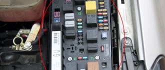
Central fuse distribution panel
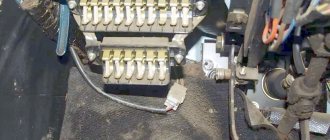
This unit is located in the rear of the engine compartment.
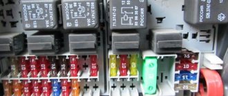
On the removed cover (7) of the central switch, a short form (6) shows the possible location of the relays and fuses. There are also small plastic pliers for disconnecting fuses. Inside the central switch, various relays (1), diagnostic plugs (2), fuses 1–21 (3), and additional fuses 23–32 (4) are visible. Next are four spare fuses (5).
Scheme
List for Audi 80, 90 models from 1989
1. Fog lights, rear fog lights 15 2. Hazard warning lights 15 3. Horn, heated seats 30 4. Clock, trunk light, vanity mirror, reading light, socket/cigarette lighter, trip computer, full automatic air conditioning, radio, auto-check system (Auto-Check-System) 15 5. Second stage cooling fan speed 30 6. Right tail light, front side light 5 7. Left rear side light, front side light 5 8. Right high beam, high beam indicator lights 10 9. Left high beam headlight 10 10. Right low beam, right headlight leveling motor 10 11. Left low beam, left left headlight leveling motor 10 12. Instrument cluster, reversing light, Auto-Check system -System), automatic transmission, differential lock, on-board computer, control system, speed control, interior lighting lamp with off delay, electronic thermal switch, operation of the cooling system fan after stopping the engine 15 13. Fuel pump 15 14. License plate lamp, lighting instruments, engine compartment lighting, glove compartment lighting, automatic air conditioning 5 15. Turn indicators, windshield wipers, windshield washer pump, heated windshield washer nozzles, cooling system fan (control unit for turning on the cooling fan after stopping the engine), air conditioning 25 16 Heated rear window, heated external rear view mirrors 30 17. Fan, automatic air conditioning 30 18. Electrically adjusted external rear view mirrors, rear window washer (station wagon) 5 15 19. Central locking system, heated door paint mechanism cylinders, alarm 10 20. First stage of the cooling system fan, turning on the fan after stopping the engine 30 21. Self-diagnosis / connecting a diagnostic tool 10 22. Free -
The electric beet lifts, electric sunroof and electric seat adjustment are equipped with automatic fuses that automatically switch on again after the fault has been corrected.
23. Free - 24. Free - 25. Lambda probe heating 5 26. Trailer socket 30 27. Ignition/injection system 10 28. Ignition/injection system 10 29. Brake light 10 30. 31. Cruise control combined with automatic transmission, ABS, differential lock 5 15 32. Ignition/injection system 10
- Fog light relay;
- Spare;
- Cooling fan relay;
- Headlight washer relay;
- Unloading relay;
- Engine cooling fan relay;
- Horn relay;
- Automatic transmission relay;
- Relay for intermittent operation of the windshield wiper and washer;
- Fuel pump relay;
- Engine cooling fan relay.
Location
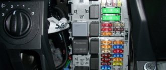
Foreign-made vehicles are mostly equipped with many electrical appliances that require protection. This is what fuse blocks are used for - to protect equipment from overvoltage. Audi 80 b3 or b4 cars, like other foreign cars, are equipped with a fuse box and relay.
The block can be found in the engine compartment. After opening the hood, you will see the fuse block (hereinafter referred to as the fuse block), which is located under the windshield. It is hidden by a plastic cover designed to protect it from moisture and debris.
This fuse box contains 31 parts that protect the wiring circuits. There are also four spare components here. In addition, in this fuse block you can see a special connector, which is necessary to connect a tester for diagnosing the on-board computer. The fuse diagram and table of their assignments is given below.
Power supply circuit
This scheme is relevant for Audi 80 b3 and b4 cars.
As noted above, in Audi 80 b3 and b4 cars, not only fuses, but also relays are responsible for the safety of devices. These components are responsible for the operation of the power windows, power sunroof, if equipped (depending on equipment) and the front seat adjustment devices. There is also a device responsible for the operation of the radiator fan of the cooling system.
Description of fuses: location, diagrams, price
| Markings/designations | What he is responsible for (with description) |
| F (F-1) / 20 | Speedometer, tachometer, gauges |
| F (F-2) / 5 | Exchange rate stabilization system |
| F (F-3) / 10 | ABS |
| F (F-4) / 10 | Reservation |
| F (F-5) / 20 | Reservation |
| F (F-6) / 30 | Glove compartment lighting |
| F (F-7) / 30 | Heater fan (stove) |
| F (F-8) / 20 | Air conditioning system |
| F (F-9) / 10 | Fuel system, fuel pump |
| F (F-10) / 10 | Safety system |
| F (F-11) / 10 | Reservation |
| F (F-12) / 10 | Powertrain sensor |
| F (F-13) / 30 | Side mirrors |
| F (F-14) / 30 | Stop signals |
| F (F-15) / 10 | Car socket |
| F (F-16) / 15 | Additional electrical network |
| F (F-17) / 15 | Hazard warning lights, turn signals |
| F (F-18) / 20 | Reservation |
| F (F-19) / 20 | Heated rear window |
| F (F-20) / 20 | Oxygen sensor |
| F (F-21) / 20 | Reservation |
| F (F-22) / 15 | Window lifters |
| F (F-23) / 20 | Automatic transmission controller |
| F (F-24) / 20 | Oven heater, cigarette lighter, interior lighting |
| F (F-25) / 15 | Reservation |
| F (F-26) / 15 | Reservation |
| F (F-27) / 20 | Reservation |
| F (F-28) / 15 | Car horn |
| F (F-29) / 15 | central locking |
| F (F-30) / 20 | Reservation |
| F (F-31) / 15 | Electrical power system |
| F (F-32) / 20 | Windshield wipers |
| F (F-33) / 20 | Headlight washers |
| F (F-34) / 20 | Rear window washer |
| F (F-35) / 20 | Fuel equipment (optional) |
| F (F-36) / 15 | Reservation |
| F (F-37) / 15 | Reservation |
| F (F-38) / 15 | Reservation |
| F (F-39) / 15 | Reservation |
| F (F-40) / 15 | Reservation |
Signs of faulty fuses on the Audi 80 B3 of the first – third generations
- The smell of melted plastic can be heard at the location of the protective modules;
- An indicator on the dashboard indicates a breakdown in the engine compartment;
- When applying current, switching speed modes, rotation speed, the equipment does not work;
- Spark marks are visible on the mounting block, which indicates insufficient fixation of the power cables.
Causes of fuse failure
- Failure to comply with technical inspection intervals for the Audi 80 B3, as a result of which the equipment functions unstable and inactive;
- Installation of non-original spare parts;
- Installation of spare parts by unqualified craftsmen;
- Mechanical damage to the unit with protective modules;
- Short circuit in the vehicle's electrical circuit;
- Damage to the insulating layer of the wiring;
- Oxidation of contacts, formation of condensation, moisture on the board;
- Loose terminal contacts.
Replacing fuses on Audi 80 B3
Preparatory stage:
- A set of new modules,
- Tweezers for removing fuses,
- Screwdriver, ratchet, 10" socket for unscrewing the board with modules.
Sequencing:
- We place the car on a flat surface, block the rear row of wheels with wheel chocks, activate the parking brake to prevent arbitrary rollback,
- Open the hood, disconnect the terminals from the battery, unclip the plastic cover, under which there is a fuse board,
- On the back of the cover there is a marking and pinout for each module. We search by ordinal index, remove with plastic tweezers,
- We insert the new module into its original place and close the lid.
To dismantle the mounting block assembly, you need to unscrew two bolts, disconnect the connectors with wires, and then remove the entire board. We carry out preventive maintenance and install it back in its original place.
Since the Audi 80 B3 has pre-installed cylindrical modules, it is not difficult to distinguish a working one from a faulty one. In the first case, the melting element will be intact and not damaged.
Relay switches are preinstalled on top of the circuit board. To replace them, you need to disconnect the block with wires from the back.
Audi 80 B3 car owners practice converting the standard mounting block with a new one with pre-installed blade-type fuses.
The process is quite complex; it is difficult to re-equip the electrical power system yourself. You will need special equipment, wires, terminals, and contacts.
Fuse Maintenance Recommendations
- After driving through puddles or in the rain, check the mounting block for moisture. Dry, blow with compressed air as necessary. Do not allow condensation to accumulate in the plastic housing,
- Buy spare parts and consumables at certified points of sale, official representative offices, dealer centers,
- Do not install over- or under-current protection modules. This will lead to a decrease in the functionality of equipment, mechanisms, units,
- Check the integrity of the fuses with special equipment - a multimeter. If necessary, contact service station specialists for help.
The average service life of fuses, relays - switches on the Audi 80 (B3) is 45 - 50 thousand km.
Additional fuse block
To gain access to the additional unit located inside the car, you need to unscrew the four screws securing the cover located under the steering wheel.
The configuration of the additional unit depends on the modification of the car, and often not all elements of the circuit may be used.
The additional unit is equipped with automatic fuses that turn off in the event of a short circuit in the network - after the fault is eliminated, they will turn on automatically.
The interior unit contains the following components of the vehicle's electrical circuit:
- common fuse;
- climate control or air conditioning control unit;
- control unit for automatic transmission and ABS system;
- control unit for electric motors of windows and sunroof;
- electronic engine control unit;
- control of heated driver and passenger seats (separate blocks for each);
- power seat controls;
- head light control system;
- interior lighting;
- seat belt and airbag controls;
- warning system for oil pressure, closed doors, etc.
Also in the wiring diagram there are unused elements (reserve), to which additional equipment can be connected: an amplifier for the speaker system, a security alarm, an electric trunk lock and other additional devices and electrical equipment.
Installing new devices or repairing electrical wiring in an Audi 80 should only be trusted to professionals - otherwise there is a high risk of the wiring catching fire.
If suddenly the fuses in the car have blown, you must first eliminate the cause of the malfunction, otherwise they will continue to burn.
You will find several videos on the topic useful:
And one more thing is also useful for checking:
Why do fuses burn?
A frequent candidate for replacement is the cigarette lighter fuse. It is located in a block located in the engine compartment and is additionally responsible for the operation of the audio system, on-board computer, interior and trunk lighting, and illumination of the mirror in the visor. Connecting a powerful compressor to inflate tires, an inverter or other equipment with high current consumption to the cigarette lighter often leads to the failure of the fuse. It is not recommended to replace it with elements of a different rating, as this may lead to electrical wiring failure. And its repair is much more expensive than the cost of the fuse.
Installing high power lamps can also cause a fuse to blow. Also, powerful lamps get very hot, which negatively affects the reflector and glass (especially if they are made of plastic). As a result of heating, the plastic glass of the headlight unit begins to transmit light worse, which negatively affects the operation of the headlights. Constantly failing fuses can cause the head light to completely disappear, making the machine impossible to operate. The maximum permitted wattage of light bulbs is indicated in the owner's manual and on the vehicle's headlights.
Independent, unqualified intervention in the on-board electrical system of a car is also a fairly common cause of failure of electrical equipment.
Exceeding the rated load on fuses, poor-quality insulation - all this can easily cause them to burn out. It is not recommended to replace burned-out elements with wires, coins, or install new ones of a higher denomination - this can lead to a fire in the electrical wiring.
Resistor
A failed heater resistor is a fairly common problem among Audi 80 car owners.
At the same time, fixing such a breakdown yourself is not so difficult. There is no need to go to a car service center and pay someone money for a relatively basic repair. You just need a new resistor, as well as an understanding of the location of the desired object.
It is not difficult to determine that the heater on an Audi 80 does not work precisely because of a resistor failure. A clear sign of such a malfunction is the heater turning on exclusively at speed 4, while fan blowing modes 1, 2 and 3 do not turn on.
Yes, first of all it is recommended to check the condition of the contacts in the control unit, as well as the integrity of the wires. It cannot be ruled out that they are the problem. But if the check did not show any problems in the electrical circuit, then the problem is in the heater resistance resistor. It periodically burns out and therefore needs to be replaced.
If we talk about the location, you will find the resistor directly on the electric motor of the stove. To access it you will need to open the glove compartment and remove it from the rails. In fact, getting to the resistor is extremely easy if you know how to remove the glove compartment.
Interior heater duct
You need to disconnect the connector with the wires and remove the resistor from the latches. The resistor fails due to the thermal fuse blowing. It needs to be replaced to restore the functionality of the element.
It's up to the motorist to decide, but Audi 80 owners usually use 2 methods:
- buy a new resistor and install it in place of the old one;
- restore the old resistance resistor through makeshift repairs.
Objectively, the best solution would be to purchase a new element that has a quality guarantee from the manufacturer. But this option is more expensive financially.
And since it is important for many to save money, it is worth describing the option of repairing and restoring the resistor
- Here you can take a piece of wire. But the option is not the best. It is preferable to use a simple 10 Amp fuse;
- Using wire cutters, the old fuse is bitten off, and a new 10-amp element is screwed in its place;
- Using copper wires in a protective sheath, as well as electrical tape, the contacts of the resistor are connected to the contacts of the fuse;
- Next, the assembly is assembled in the reverse order;
- The performance of the heater is checked at all speeds.
The experience of motorists shows that such a repair scheme for the heater resistance resistor on Audi 80 cars has every right to exist. But if in doubt, just buy a new resistor and change it according to the instructions. This is literally 10 minutes of your time.
Heating system radiator
Although fuses, relays and resistors are small parts of a car, they can play a key role in many issues. Including the performance of the heating system on Audi 80 cars in different bodies.
Moreover, checking the condition of the components considered is quite simple. The automaker has provided convenient access to the fuse box and resistor. Even the heater control unit is not as difficult to disassemble as some might think. A few latches and mounting screws separate you from it.
Where to look for the fuse
First, let's look at the heater fuse on the Audi 80. Regardless of which body is relevant for your car, B3 or B4, the location and diagram are the same.
You should look for the block you need in the engine compartment. When you open the hood of your Audi, you will see the fuse box there. You need to look in the area under the windshield. Please note that you may not notice it right away, since the block is covered with a special plastic cover. This is necessary to protect against external harmful influences in the form of debris and moisture.
In total, the Audi 80 safety block contains 31 elements, as well as 4 additional components, the so-called spare ones. The location of fuses and relays is relevant for B4 and B3, so the circuit can be considered universal.
Here you will find a special connector. It is used in situations where it is necessary to connect a tester or other diagnostic equipment to check the status, errors and functionality of the on-board computer of your Audi 80.
Disassembled interior heater
If we talk about the stove fan we are interested in, it is located at number 17 and has a rating of 30 Amperes. When replacing, use only a similar component of the same rating. It is strictly not recommended to use fuses for more or less amperes.
To avoid any confusion when searching for the right fuse, simply rely on the cover of the fuse block. On the reverse side there are corresponding labels that allow you to understand where which fuse or relay is and what they are responsible for.
There should also be no difficulties with the procedure for replacing a burnt-out element. The work is extremely simple if you follow the instructions and follow the basic recommendations. Replacing a fuse on an Audi 80 is carried out in the following sequence:
- To begin, turn off the engine and raise the hood. Be sure to remove the negative terminal from the car battery to completely cut off the power to the car. It is not necessary to remove and put away the entire battery. It is enough to remove the minus;
- Using a screwdriver, remove the protective cover from the safety block. Flip the cover over to see the layout that applies to your unit. Although there is no detailed description there, the printed symbols make it possible to figure out where each fuse and relay are, as well as what protective functions they perform;
- Also, special tweezers must be attached to the lid. But since the Audi 80 is already quite an old car, the tweezers could get lost over a long service life. You should not try to manually pull out the fuse, as you can easily accidentally damage other fusible elements. It is better to use something like tweezers from a manicure set, or small pliers;
- Remove the heater fan fuse and visually check its condition. If it has melted and become deformed, then the fan definitely does not turn on due to a lack of power, which the fuse has broken;
- Take a similar fuse with the same rating and carefully insert it into the socket instead of the old heater fan protection element.
All that remains is to check the heater for functionality. Please note that fuses do not simply blow. There must be a proper reason for this. You need to understand why the fuses are burning and fix the problem.
This is usually due to wear on the electric motor, as well as problems in the electrical wiring. Sometimes the contacts oxidize, or damage to the wires themselves occurs, breaks, etc. It is recommended to check the condition of the wiring leading to the electric motor of the stove, and if necessary, replace them and clean all contacts.
If the cause is not eliminated, the new fuse will burn out as quickly as the previous one. Further constant replacement of fuses will be completely pointless as long as there is a reason that contributes to overloading the electrical circuit of the stove.
Interior heater assembled
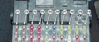
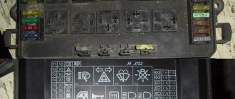
Fuse box in the engine compartment
- relay
- diagnostic connector
- fuses 1-21. Cars with diesel engines have 22 fuses.
- additional fuses 23-32
- four spare fuses
- relay designation on the distribution panel cover
- clamp for removing and installing fuses
Scheme of this block
Decoding
| № | Purpose |
| 1 | 15A Fog lights, rear fog lights |
| 2 | 15A Hazard alarm |
| 3 | 30A Horn, heated seats |
| 4 | 15A Electronic clock, trunk light, interior light, vanity mirror, reading light, cigarette lighter, on-board computer, automatic air conditioning, radio, self-diagnosis system |
| 5 | 30A 2nd speed radiator fan |
| 6 | 5A Rear right side and parking lights |
| 7 | 5A Rear left side and parking lights |
| 8 | 10A Right high beam headlight, high beam warning light |
| 9 | 10A Left high beam headlight |
| 10 | 10A Right low beam headlight, right headlight adjustment motor |
| 11 | 10A Left low beam headlight, left headlight adjustment motor |
| 12 | 15A Instrument panel, reversing lights, control system, automatic transmission, differential lock, on-board computer, speed control, retarder relay, interior lighting with, electronic thermal switch, relay for turning on the radiator fan |
| 13 | 15A Fuel pump |
| 14 | 5A License plate light, instrument panel light, engine compartment light, glove compartment light, automatic air conditioning |
| 15 | 25A Turn signals, windshield wiper, windshield washer pump, heated windshield washer nozzles, radiator fan relay, air conditioning |
| 16 | 30A Heated rear window, heated mirrors |
| 17 | 30A Interior blower fan, automatic air conditioning |
| 18 | 5A Electric mirrors |
| 18 | 15A Rear window wiper (Avant) |
| 19 | 10A Central locking, heated lock switch cylinder, anti-theft system |
| 20 | 30A Radiator blower, 1st speed, interior fan |
| 21 | 10 Diagnostic connector |
| 22 | Not used (vehicles with gasoline engines) |
| 22 | 80A Glow plugs (vehicles with diesel engines) |
Additional fuses for Audi A 80 B4 bottom row (if equipped)
| 23 | Not used |
| 24 | Not used |
| 25 | 5A Lambda probe heating. Not used for vehicles with diesel engines |
| 26 | 30A Trailer Connector |
| 27 | 10A Ignition/fuel injection system |
| 28 | 10A Ignition/fuel injection system. Not used for vehicles with diesel engines |
| 29 | 10A Brake light |
| 30 | 5A Speed control (vehicles with automatic transmission), Not used for vehicles with diesel engines. |
| 31 | 15A ABS, differential lock |
| 32 | 10A Ignition/fuel injection system For vehicles with TD diesel engines - fuel shut-off valve |
Fuses 27 and 28 can be equipped with a red plastic cover with the inscription “Motor/Moteur”
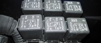
Relay
- Relay for fog lights and tail lights. For cars without fog lights, there is a jumper in this place
- Radiator fan relay (for cars without air conditioning), radiator fan relay for turning on the 2nd stage of rotation
- Fan relay
- Headlight washer relay
- X-contact unloading relay
- Interior blower relay (manual air conditioning), air conditioning fan relay for speed at 2nd stage (automatic air conditioning)
- Horn relay
- Anti-theft alarm relay (vehicles with manual transmission). Cars without such a system have a jumper. For vehicles with automatic transmission this space is free.
- Wiper interval relay
- Fuel pump relay
- Radiator fan relay for turning on the 1st stage of rotation.
Repair and maintenance book
If you still have questions, ask them in the comments or download the repair and operation manual for the Audi 80 1991-1995: “ “. To view, use the djvu reader program.
Each electrical device in a car is designed for a specific voltage. The diameter of the supply wire is calculated taking into account this voltage. If the current consumption in a certain circuit, for example, due to the connection of additional consumers, increases, then the supply wire experiences additional load. It may overheat or even burn out if the flow of current is not interrupted in a timely manner. This function is performed by fuses. To avoid complete blackout of the on-board network, each circuit has its own fuse. However, connections to the battery, alternator, starter and ignition switch do not have fuses.
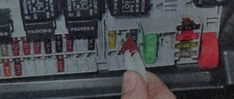
To remove and replace fuses, use the plastic clip that is attached to the cover of the central distribution panel (see illustration 3.0).
If a new fuse blows immediately after installation, make sure that the fuse of the required rating was installed, and not a smaller one. If the rating corresponds, then check individually all consumers of this circuit. Use the appropriate electrical diagram for this. If necessary, disconnect all consumers in the circuit and then connect one at a time. If, when connecting the next consumer, the fuse blows, then this consumer is faulty.
14.2.1.4. Identifying Contacts on the Fuse and Relay Box Boards
Identification of relay blocks (Audi-80/90)
| 1. Fog lights J5 2. Radiator cooling fan (stage 2) J101 3. Engine-off radiator cooling fan control unit J138 4. Not used 5. Load reduction relay J18 | 6. A/C fresh air blower J11 7. Horn J4 8. Jumper between pins 36 and 38 of manual transmission 9. Automatic transmission J60 10. Fuel pump J17 11. Radiator cooling fan (stage 1) J26 |
Identifying Contacts on the Fuse and Relay Box Boards
| RELAY BOX LOCATION | CONTACT NUMBER | NUMBER ON RELAY BOX | USAGE |
| 1 | 10 | 86 | Fog lamps |
| 11 | 30 | ||
| 12 | 85 | ||
| 13 | 87 | ||
| 2 | 14 | 30 | Radiator Cooling Fan High Speed Relay |
| 15 | 85 | ||
| 16 | 87a | ||
| 17 | 87 | ||
| 18 | 86 | ||
| 3 | 1 | 15 | Radiator cooling fan control unit when the engine is off |
| 2 | 30 | ||
| 3 | 31 | ||
| 4 | |||
| 5 | ST1 | ||
| 6 | |||
| 7 | 87 | ||
| 8 | |||
| 9 | |||
| 4 | Open | ||
| 5 | 24 | 30 | Load reduction relay |
| 25 | 85 | ||
| 26 | 87 | ||
| 27 | 86 | ||
| 6 | 58 | Air conditioner relay | |
| 28 | 86 | ||
| 29 | 87a | ||
| 30 | 30 | ||
| 31 | 85 | ||
| 7 | 32 | 87 | Sound signal device |
| 33 | 86 | ||
| 34 | 30 | ||
| 35 | 65 | ||
| 8 | 36 | 87 | Automatic transmission |
| 37 | 86 | ||
| 38 | 30 | ||
| 39 | 85 | ||
| 9 | 40 | 53e | Windshield washer and wiper switch |
| 41 | 53c | ||
| 42 | 31b | ||
| 43 | 15 | ||
| 44 | 31 | ||
| 45 | I | ||
| 10 | 46 | 15 | Fuel pump |
| 47 | T | ||
| 46 | 30 | ||
| 49 | L | ||
| 50 | 31 | ||
| 51 | 1 | ||
| 52 | 87 | ||
| 53 | |||
| 59 | |||
| 11 | 54 | 87 | Radiator Cooling Fan Low Speed Relay |
| 55 | 86 | ||
| 56 | 30 | ||
| 57 | 85 |
Identification of relay blocks (Audi-80/90, 80/90 Quattro and Coupe, starting from models 1989)
| 1. Fog lamps, J5 2. Not used 3. Engine off radiator cooling fan control unit, J138 4. Headlight washer system, J39 5. Load reduction relay, J18 6. Radiator cooling fan high speed relay, J101 | 7. Horn, J4 8. Jumper between manual transmission pins 36 and 38 8. Automatic transmission, J60 9. Windshield washer/wiper switch, J31 10. Fuel pump, J17 11. Radiator cooling fan low speed relay, J26 |
Identifying Contacts on the Fuse and Relay Box Boards
| RELAY BOX LOCATION | CONTACT NUMBER | NUMBER ON RELAY BOX | USAGE |
| 1 | 10 | 86 | Fog lamps |
| 11 | 30 | ||
| 12 | 85 | ||
| 13 | 87 | ||
| 2 | Open | ||
| 3 | 1 | 15 | Radiator cooling fan control unit when the engine is off |
| 2 | 30 | ||
| 3 | 31 | ||
| 4 | T | ||
| 5 | ST1 | ||
| 6 | |||
| 7 | 87 | ||
| 8 | |||
| 9 | |||
| 4 | 19 | 30 | Headlight washer system |
| 20 | 85 | ||
| 21 | 86 | ||
| 22 | 87 | ||
| 23 | |||
| 5 | 24 | 30 | Load reduction relay |
| 25 | 85 | ||
| 26 | 87 | ||
| 27 | 86 | ||
| 6 | 58 | 87 | Radiator Cooling Fan High Speed Relay |
| 28 | 86 | ||
| 29 | 87a | ||
| 30 | 30 | ||
| 31 | 85 | ||
| 7 | 32 | 87 | Sound signal device |
| 33 | 86 | ||
| 34 | 30 | ||
| 35 | 85 | ||
| 8 | 36 | 87 | Automatic Transmission Jumper (Manual Transmission) |
| 37 | 86 | ||
| 38 | 30 | ||
| 39 | 85 | ||
| 9 | 40 | 53e | Windshield washer and wiper switch |
| 41 | 53c | ||
| 42 | 31b | ||
| 43 | 15 | ||
| 44 | 31 | ||
| 45 | I | ||
| 10 | 46 | 15 | Fuel pump |
| 47 | T | ||
| 46 | 30 | ||
| 49 | L | ||
| 50 | 31 | ||
| 51 | 1 | ||
| 52 | 87 | ||
| 53 | |||
| 59 | |||
| 11 | 54 | 87 | Radiator Cooling Fan Low Speed Relay |
| 55 | 86 | ||
| 56 | 30 | ||
| 57 | 85 |
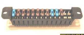
Fuse and relay block board, contacts for wiring connections
| A – Contacts for connecting the plug of the air conditioning system, color gray B – Contacts for connecting the plug of the front right wiring harness, color black C – Contacts for connecting the plug of the instrument cluster, color blue D – Contacts for connecting the plug of the front left wiring harness, color green E – Contacts for connecting the plug of the front left wiring harness, color yellow F – Contacts for connecting the plug of the instrument cluster, color brown G – Contacts for connecting the plug of the instrument cluster, color red | H – Contacts for connecting the plug of the rear wiring harness, color black I – Contacts for connecting the plug of the instrument cluster, color red J – Contacts for connecting the plug of the instrument cluster, color yellow K – Contacts for connecting the plug of relay 3, color black L – Contacts for connecting single plug (terminal 30), color clear M – Contacts for connecting a plug of non-standard equipment installed on request, color clear N – Not used O – Not used P – To fuse 20 |
| previous page14.2.1.3. Fuse locations and identification | next page 14.2.1.5. Additional relay block board |