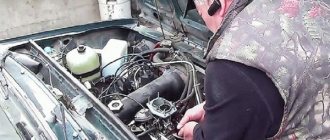
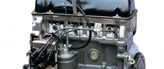
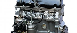
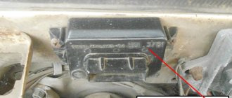
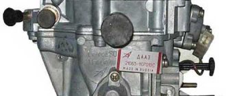
Causes related to the carburetor
Carburetor choke is not fully open
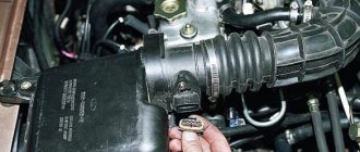
After the engine has warmed up, the choke handle should be recessed and the carburetor air damper should be fully open. The engine is warmed up using an enriched mixture, for which purpose the air damper is closed with the choke handle. If the damper is constantly closed, the fuel mixture is over-enriched, and this leads to an increase in the car’s appetite. The choke handle is recessed and the position of the air damper is checked. If it is not fully open, there is a malfunction; it is necessary to adjust the choke drive, or eliminate the jamming of the damper.
Air damper carburetor VAZ 2107
Valve XX VAZ 2107
Fuel enters the idle system through the nozzle; if it is not screwed in completely, additional fuel will bypass the nozzle, enriching the mixture. The idle system operates in all engine modes. And every time we press the gas pedal, we force the engine to suck in an extra portion of fuel, leading to excessive fuel consumption.
Float chamber needle valve leaking
Needle valve VAZ 2107
A working needle valve of the float mechanism should shut off the flow of fuel into the carburetor at a certain level necessary for normal engine operation. If this level is exceeded, the fuel mixture entering the engine will be over-rich. If the fuel valve does not cope with its task, the fuel level in the float chamber will increase, and with it the fuel consumption will increase. This may happen due to a trapped speck or a valve malfunction. Moreover, the flow of additional fuel into the float chamber may be insignificant and unnoticeable, but fuel consumption will increase by a liter or one and a half. Therefore, it is worth checking the functionality of the shut-off needle valve or replacing it with a known good one.
The air jets of the main metering system or the idle system are clogged
GDS jets VAZ 2107
Clogged air jets will result in a richer mixture formed by the carburetor. It is necessary to clean and blow out the jets.
System XX carburetor VAZ 2107
To clean the jets, it is necessary to use softer materials than the jet material, so as not to damage the latter (for example, copper wire).
The forced idle economizer system is faulty
EPHH is designed to cut off the fuel supply while the car is moving with the gas pedal released and the gear engaged; it is also called engine braking mode or forced idle. If the system is faulty, when the engine brakes, fuel will be actively sucked through the idle system, no savings will be achieved, and overall gasoline consumption will increase.
EPHH VAZ 2107
The idle speed economizer valve of the VAZ 2107 may not close the outlet at idle for the following reasons: - malfunction of the pneumatic valve control unit; — pneumatic valve malfunction; — malfunction of the microswitch or violation of its installation; — malfunction of the idle speed economizer.
What is an economizer and why is it needed?
An economizer is a specially designed device for carburetor engines. Its main functions include regulating the intake of the combustible mixture.
The following types of forced idle economizers are used in cars of the domestic manufacturer VAZ:
- EPHV - sometimes also called a solenoid valve (EMV).
- EMR (power mode economizer).
EPHH allows excellent gas savings, especially when driving on uneven terrain. During long descents, it suspends the fuel supply through the idle system. This is how engine braking occurs.
This driving mode has a beneficial effect not only on the driver’s wallet, since fuel is consumed more slowly, but such driving is also much safer. After all, when driving on a descent, the car is more confident and safer compared to driving in neutral gear.
DIY adjustment
Each car owner of a “six” or “seven” has the ability to adjust the carburetor independently. Adjustment work can enhance the dynamic qualities of the car, as well as reduce gasoline consumption. Undoubtedly, these are important indicators for any car owner, so you should be responsible when adjusting the carburetor.
Preparatory stage
Before you start work, you need to prepare thoroughly. This stage is necessary to ensure that nothing distracts the driver during setup and configuration.
First, it is recommended to prepare your work area. The carburetor must be installed on a flat and hard surface; it is better to stock up on rags in advance, as gasoline leaks are possible. In addition, it is necessary to ensure that the room in which the adjustment is planned is well ventilated and has high-quality lighting.
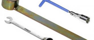
The second point of preparation is the set of necessary tools. You will need to prepare in advance a set of wrenches and two screwdrivers - a Phillips and a flathead with a narrow blade.
Next, find the service book for your car. It is there that the operating parameters are indicated, which will need to be checked during adjustment.
How to enrich or lean the mixture
Enriching or depleting the air-fuel mixture must be done at engine idle speed:
Start the engine and wait until it warms up to its operating temperature.
Tighten the fuel quality and quantity screws until they stop.
Next, unscrew each screw 3 turns back.
Referring to the idle speed data given in the VAZ service book, set the required number of revolutions by adjusting the screws in one direction or another.
That is, the principle of adjusting the mixture is to set the idle speed recommended by the manufacturer by reducing or increasing the enrichment of the mixture (quality screw) and reducing/increasing the amount of mixture (quantity screw).
At the bottom of the tube there is a quality screw, and a little to the right in a tube of smaller diameter there is a quantity screw
How to reduce gasoline consumption
The main element in a carburetor is the float. After you have adjusted the enrichment/leanness of the mixture, the float will invariably return to its axis. However, it may be slightly higher than normal - in this case, fuel consumption will increase. In addition, adjusting the float is also necessary in order to reduce the toxicity of gas emissions, since due to poor-quality sealing of VAZ cars, some gases can enter the cabin.
Adjustment of the float mechanism is carried out on a completely cooled motor. In order to get to it, you will need to remove the air filter box and unscrew the carburetor cap:
The float tongue needs to be adjusted.
The float stroke should correspond to the recommended value of 8 mm. If on a VAZ 2106/2107 this value is greater, fuel consumption increases; if it is lower, losses in dynamics appear.
Adjusting the clamps and axle fastenings allows you to set the desired stroke.
Then you need to install the cover on the carburetor and screw the filter box into place.
Adjustment of the float tongue is ensured by screws and clamps
Video - Installation of the EPHH system
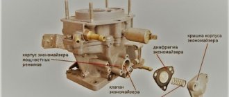
An increase in fuel consumption can be due to many factors, including improper operation of the EMR. If the valve spring is weakened or broken, the economizer valve will be constantly open, re-enriching the air-fuel mixture. When the gas pedal is fully pressed, this increases engine power, but in other modes, on the contrary, it leads to a drop in power. Because of this, the driver is forced to press harder on the gas, which further increases fuel consumption. If the EMR diaphragm has lost its seal or the cap is not tightened properly, gasoline will enter the intake manifold below the throttle valve and also leak out. The latter is especially dangerous because it can cause fuel to ignite.
Not enough air
Often the car starts up well and runs on choke, but as soon as the choke is turned off, the engine stalls. This indicates only one thing - lack of air. Most likely the air jets are clogged. They need to be unscrewed and cleaned. Then check that the car should not stall without suction.
There are an incredible number of reasons for poor performance of car components with similar symptoms, but only a specialist with a set of professional diagnostic tools can figure them out. But if you feel confident in yourself, go for it, VAZ service centers are already waiting for you.
Diagnostics and repair of EPHH
Diagnosing a faulty economizer is not that difficult; you just need to understand how it works and the principle of operation of the economizer. In the future, you will be able to eliminate the main difficulties yourself.
You can replace the EPHH or clean the jet without dismantling the carburetor. The procedure is carried out as follows:
- Carefully remove the air filter.
- Disconnect the power wire from the economizer, after which it should be unscrewed from the housing.
- Remove the jet and thoroughly wash it in kerosene.
- Briefly connect the economizer to the battery. If the drive is more than 5 mm, this indicates normal operation of the device. Otherwise, it will have to be replaced with a new one.
Troubleshooting the unit
Upon completion of diagnostic operations on the VAZ 2107 engine, other breakdowns that may have similar manifestations should be excluded. The econometer works by changing the pressure in the carburetor channels; damage to its tube can lead to air leaks. A modern injector electronic control system eliminates electro-pneumatic devices that are less reliable.
An accurate determination of the cause of the EPHH malfunction is only possible if the unit is dismantled and completely disassembled. The economizer is removed from the carburetor in the following order:
- Using a “10” wrench, unscrew the 3 nuts holding the filter cover and lift it up along the studs.
- Unscrew two Phillips-head screws that secure the pneumatic block with the membrane and valve. The control tube is removed from the fitting of the device.
- The device is removed from the socket and carefully inspected for damage and carbon deposits on the valve or its seat.
The operation scheme of the carburetor, which was replaced by an injector, assumes a reaction to changes in pressure in the chamber with a decrease or increase in fuel supply. The economizer implements this feedback through a flexible membrane rigidly connected to the stem and valve
When checking this block, special attention should be paid to this node
There are repair kits for sale for Solex carburetors that were previously installed on the VAZ 2107. The forced idle unit, if it does not work, can be repaired using parts from such a kit. Installation of the unit in its intended place must be accompanied by a leak test. The last thing to connect before installing the air filter is the econometer located on the control panel. The position of the arrow in the green sector indicates acceptable fuel consumption.
Question. My car (VAZ-21044i 2000 (1700i engine, GM controller 21214-1411010/10 (EFI))) has an instrument panel from a VAZ-2107 that has an ECONOMIZER. As far as I know, it instantly indicates the fuel economy mode when driving (in response to the gas pedal). On my car, when starting the engine and driving, it is constantly in the red zone (arrow on the left) and there is no response to the gas pedal. As the engine warms up and drives (20 minutes), the needle gradually drops into the green zone (arrow in the center); when driving for about 1 hour, it comes closer to the edge of the green zone. At the warranty service station they told me that it would not work because... The sensor hose is connected not at the inlet (as on a VAZ-2107 car), but at the outlet to a tee near the adsorber. Should the economizer work on my car? If YES, then how to work. If it should work like on the VAZ-2107, then tell me how to fix this problem? Car enthusiast Konstantin Vasilievich Sidko, Kiev.
Answer. Actually an "econometer". A device that measures the vacuum in the intake pipe is quite useless for you. With the disappearance of the carburetor, which operates under vacuum, and the advent of trip computers capable of showing instantaneous and hourly consumption in particular. Back in 1984, the econometer was considered uninformative by German carburetor eight testers. You can revive it, since it is there anyway, as follows: Either in the hose from the tee you mentioned to the combination, or in the fitting of the combination there is a clogged damping nozzle. It is needed so that the needle does not twitch due to the cyclic operation of the pistons. Blow air under low pressure or pierce this jet with copper wire. It may contain debris, oil, condensate, fuel. Yakovlev Alexander Anatolyevich. Engine Design Department, Fuel Equipment and Toxicity Department
Owners of injection sevens will not find this material useful, unlike owners of Lada cars with a carburetor engine. After all, it was the carburetor models of the sevens that were equipped from the factory with such a device as the EPHH system of the VAZ 2107. If by the name of the economizer it is difficult to even imagine what it is, then by deciphering the EPHH - forced idle economizer, it becomes a little clearer what we are talking about.
What is an economizer and why is it needed?
An economizer is a device that regulates the fuel supply. The following types of economizers are used in carburetors of VAZ cars:
- Forced idle economizer (EFES), which is sometimes called a solenoid valve (EMV).
- Power mode economizer (EMR).
The EPHH is installed in the upper part of the carburetor, under the air filter and consists of a solenoid, a plastic actuator (its functions are similar to a needle valve) and an idle jet. It turns off the fuel supply through the idle channel to the mixing chamber if two conditions are met: the crankshaft rotation speed exceeds 1.7–2 thousand revolutions per minute and the driver’s foot is not on the gas pedal. The signal to turn on the EPHH is supplied by the control unit connected to the microswitch and the ignition system. ECP seriously saves fuel when driving in mountainous areas. During long descents, it blocks the fuel supply through the idle system and the car goes into engine braking mode. In addition to saving fuel, this increases traffic safety, because on a long descent, the car’s controllability and stability in a low gear is much higher than in neutral.
The EMR is installed in the lower part of the carburetor, under the EPHH. This device consists of a spring-loaded diaphragm and a valve. In a quiet state (when the engine is turned off), the membrane spring presses on the ball, pushing through the resistance of its spring, due to which gasoline passes freely through this valve, passes through the channel and enters the atomizer. When the engine is running, the vacuum that occurs below the throttle valve weakens the influence of the diaphragm spring, as a result of which the valve spring squeezes the ball and the latter blocks the flow of gasoline into the fuel channel. If the gas pedal is pressed harder than 2/3, the vacuum below the throttle valve drops and the valve opens the way for fuel to the mixing chamber nozzle. As a result, the mixture becomes richer, which provides increased engine torque.
Setting the float chamber level
This is the first step in adjusting any carburetor. It is on this part that the consumption and stability of the engine will depend.
The level must be at the nominal level set by the manufacturer, so it is very important to follow the technology
Setting the fuel level in the float chamber: I - carburetor cover; 2 — needle valve seat; 3 - emphasis; 4 - needle valve; 5 - locking needle ball; 6 - valve needle pull-out fork; 7 — float bracket; 8 - tongue; 9 — float; 10 - gasket.
The top cover of the carburetor is removed, but before that, you need to pump up the manual fuel pump to check the set level. The nominal level is the level of gasoline located on half of the inclined surface. If it is higher or lower, then adjust the float level by bending the adjusting antennae. The XX speed is also regulated by the float chamber.
To check, just put the cover on top, start the engine and immediately turn it off. Open the lid again and check the level. After this, you can move on to the next stage.
Diagnostics and repair of EPHH
Diagnosing a faulty economizer is not that difficult; you just need to understand how it works and the principle of operation of the economizer. In the future, you will be able to eliminate the main difficulties yourself.
You can replace the EPHH or clean the jet without dismantling the carburetor. The procedure is carried out as follows:
- Carefully remove the air filter.
- Disconnect the power wire from the economizer, after which it should be unscrewed from the housing.
- Remove the jet and thoroughly wash it in kerosene.
- Briefly connect the economizer to the battery. If the drive is more than 5 mm, this indicates normal operation of the device. Otherwise, it will have to be replaced with a new one.
All repair and diagnostic work must be carried out with a dry carburetor, that is, the fuel must be drained from it.
To independently diagnose a malfunction of the EMR injection VAZ 2107, we suggest you watch the video:
The economizer on the VAZ 2107 does not work
Dear visitors of the “Cars” website! We will be very grateful for your comments on the video clip “The Economizer on the VAZ 2107 does not work”; registration is not required for this. We also ask you to let us know if you have any problems playing the video.
I have a 2002 Seven, I’ve been driving it every day for 5 years, there have been no problems with EPHH, why don’t I understand why it’s causing crap? And even if it doesn’t take long to fix it
Hello Nail Mukhamedovich. On my VAZ 21053 the pneumatic electric valve is looped. Does this mean the previous owner broke it and he looped it? The economizer control unit does not respond when it is turned off. This is how it should be, as I understand from the video? How to check the functionality of the microswitch? Also, should I remove the clamps and try some throttle?
How to check the functionality of the PEC? Is it generally possible to drive like this when the PEC is looped, in the sense that there is no harm to the engine?
But as?
Nail Mukhamedovich, for example, I will do the same as in this video, but what should I do with the old pneumatic valve on the spar, or rather with the wires that are connected to it, if I remove the wires the car will stall? even if it is no longer involved in engine operation
Nail Mukhamedovich thank you
Nail Mukhamedovich I have a carburetor 2105 1107010-10, I saw how you replaced the economizer and installed an electric jet instead. magnetic valve, mine also does not have an economizer and does not have this valve, tell me, should I install it or not? I don’t have a hole for the valve there, but in all likelihood the EPHH system was installed because all the elements are present except the economizer.
Thank you Uncle Nail for all the advice for a long life to you
Nail, I went to all the auto stores in my city and still haven’t found this mixture quantity screw, some people call it a mixture quantity indicator. I would be very grateful if you could tell me where I can order and buy it, if you have it and you can send it to me, I would paid all expenses.
If, as in the first case, you throw a hose onto the manifold, and everything is fine, does that mean the solenoid valve is not working? The problem is that at 1500 rpm the speed starts to float, as in the video, if you raise it to 2x then everything becomes ok. I threw the hose straight on and the problem disappeared, does that mean the problem is in the valve?
Hello, Nail Mukhamedovich. I bought a car, the carburetor is 2107-1107010. The former owner connected the hose directly from the economizer to the manifold as in your video. I installed a quantity screw, tomorrow I will buy and install a magnetic valve. The question is: where does the hose from the manifold go? Shut up?
Hello, tell me, I check the operation of the pneumatic valve at idle, disconnect the contact from the valve, the car continues to work, it doesn’t stall, then I connect the contact, the valve clicks, I check with a tester that there is approximately 12 volts, then I disconnect the block from the pneumatic valve control unit, the car continues to work. But what’s interesting is if I give the gas a little , at idle, the car may stall, but if you accelerate quickly, then no. What could this be? Thank you. By the way, I changed the microswitch because the lever on which the throttle is held was slipping behind it
Emil, why write a video when you are a little hot?
But what if instead of the electric valve we put a plug?
hello nail, I’m writing to you again, I once wrote to you about EPHH, I decided to remove the economizer and install everything as in your video, but now after re-gasping, the pneumatic valve clicks? and please explain how it is correct to leave everything connected or can you disconnect both the control unit and the pneumatic valve????? I decided to remove the economizer because I had to drive a little far and after a long drive, somewhere around one hundred and twenty, I drove for about three hours. When installing, the revs dropped and rose to a stalemate. I turned it off, stood for a while, started it up, everything seemed to stabilize, but I didn’t take any risks and changed everything as in your video.
all these epkhh in the trash the wire from the coil to the valve and forward
Uncle Nail, tell the fool... 99 Solex, I put the gas to the floor and see an explosion in cell 1, like a firecracker, I was already scared, what kind of joke?
Well done
how to adjust the carburetor on a VAZ 2107
Thanks to Nail Poroshin, I became a carburetor specialist...
Replacing the economizer
Before starting work, you should collect all the necessary tools, then the replacement process will go much faster. You can make the replacement yourself, just follow these instructions:
- The engine must cool down for an hour before you can proceed with replacement.
- Using a 10 mm wrench, unscrew all the bolts that secure the air filter cover.
- Next, take a size 8 wrench and use it to unscrew the main fixing bolts. You now have access to the economizer sensor and carburetor.
- Now disconnect the connector that powers the micro valve.
- Using a screwdriver, unscrew the 2 bolts securing the EPH sensor.
- Remove the hose from the fitting, then move it to the side (it is advisable to fix it so that it does not interfere in the future).
- There is a spring installed under the panel located behind the sensor. It must be removed carefully, otherwise it may jump out and get lost. After installing the economizer, the sensor and spring should be replaced, as they begin to work worse over time.
- Then the entire system is installed; video tutorials from experienced car enthusiasts will help you with this.
Replacing the idle speed sensor
The idle speed sensor of the VAZ 2107 can only be removed together with the throttle body. To avoid burns when performing work, you must ensure that the engine is cool. To dismantle the sensor, perform the following operations:
After removing the sensor, you need to check the O-ring located at the mounting location of the idle speed sensor. If it is cracked or inelastic, it must be replaced.
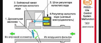
Checking the idle speed sensor consists of monitoring the resistance between the terminals of its windings. Between AB and CD it should be approximately 53 Ohms, between AC and BD it tends to infinity. If the resistance is different, the idle speed sensor must be replaced with a new one.
Before installing a new sensor, you need to check the amount of protrusion of its needle. It should protrude no more than 23 mm. You can check this like this:
Apply plus to terminal D of the VAZ 2107 idle speed sensor.
Touch the ground wire to terminal C of the idle speed sensor. The needle will move out a little. Using repeated touches, simulating impulses from the power source, push the needle so that it takes the extreme position.
Use a caliper to check the size of the protrusion. If the needle protrusion is more than 23 mm, the sensor must be replaced with a new one.
Before installing the idle speed control, it is necessary to lubricate the rubber O-ring with machine oil.
Installation of the idle speed sensor occurs in the reverse order of removal. During installation, it is necessary to check the serviceability of the band clamps and, if necessary, replace them. It is also necessary to take into account that it is necessary to install the throttle body only on a new gasket.
Carburetor VAZ 2107 idle
is ensured using a forced idle economizer system (EFI). In order to detect a system malfunction, this article describes methods for checking and replacing all components of the forced idle system of a VAZ 2107 carburetor.
Purpose of the economizer for carburetor power modes
EMR is necessary to saturate the combustible mixture through the carburetor. In this case, the throttle opens and the engine starts running at full speed. In this situation, the engine power increases significantly, plus there is an additional opportunity to increase speed.
Some users install an EMR economizer on the VAZ 2107 carburetor precisely to increase power. But they must be able to do this competently, since while driving the load on the engine increases, which, of course, can lead to engine failure.
EPHH on VAZ 2107 (diagram, photo and video)
Cars of the Volzhsky Automobile Plant of the seventh model were equipped with Solex carburetors. One of the features of this unit is the presence of a special device - EPHH for controlling the idle mode of the VAZ 2107 engine. To reduce fuel consumption, the driver has an econometer installed; the device circuit allows you to control its consumption while driving.
The forced idle economizer (hereinafter referred to as the economizer) ensures that the crankshaft rotation speed is maintained within the range of 840 -920 rpm. The VAZ 2107 engine operates in this mode without load, and the device regulates the supply of the mixture to the primary chamber of the carburetor. This device was used until they began installing an injector and a more advanced power system on power units.
Device malfunctions and their manifestations
The stability of the engine operation depends on the serviceability of the EPHH, and the failure of this device leads to the following unpleasant consequences:
- Unstable engine idling: spontaneous increase or decrease in speed. In some cases, the power unit simply stalls.
- A sharp increase in gasoline consumption while driving, especially in urban mode.
- A faulty economizer unit, which is installed on the carburetor, does not allow the idle speed to be adjusted correctly.
- The ecometer does not provide correct readings.
The standard engine operation control circuit in this mode does not allow the slightest violation of the system's tightness or its clogging. The main reasons for the failure of this unit are cracks in the membrane or clogging of the channels with solid deposits resulting from the use of low-quality fuel.
Troubleshooting the unit
Upon completion of diagnostic operations on the VAZ 2107 engine, other breakdowns that may have similar manifestations should be excluded. The econometer works by changing the pressure in the carburetor channels; damage to its tube can lead to air leaks. A modern injector electronic control system eliminates electro-pneumatic devices that are less reliable.
An accurate determination of the cause of the EPHH malfunction is only possible if the unit is dismantled and completely disassembled. The economizer is removed from the carburetor in the following order:
- Using a “10” wrench, unscrew the 3 nuts holding the filter cover and lift it up along the studs.
- Unscrew two Phillips-head screws that secure the pneumatic block with the membrane and valve. The control tube is removed from the fitting of the device.
- The device is removed from the socket and carefully inspected for damage and carbon deposits on the valve or its seat.
The operation scheme of the carburetor, which was replaced by an injector, assumes a reaction to changes in pressure in the chamber with a decrease or increase in fuel supply. The economizer implements this feedback through a flexible membrane rigidly connected to the stem and valve
When checking this block, special attention should be paid to this node
There are repair kits for sale for Solex carburetors that were previously installed on the VAZ 2107. The forced idle unit, if it does not work, can be repaired using parts from such a kit. Installation of the unit in its intended place must be accompanied by a leak test. The last thing to connect before installing the air filter is the econometer located on the control panel. The position of the arrow in the green sector indicates acceptable fuel consumption.
Operating principle
To determine the cause of the problem and take action to troubleshoot the EPHH, you need to know about the principle of its operation.
- The economizer is equipped with output and input circuits.
- The input circuits are a limit switch and a wire that connects to the switch.
- The throttle (throttle) limit switch tells the economizer whether the gas pedal is depressed or not at that particular moment.
- If the pedal is not depressed, the limit switch closes to ground.
- As soon as the gas pedal is pressed by the driver, the contact is switched off.
- The wire that connects the switch and the economizer reports the number of pulses to the ignition coil. In fact, due to this, the economizer is able to find out about the actual current speed of the power unit.
- The EPHH has only one output circuit - the XX solenoid valve of the carburetor system (XX - idle speed). The economizer can turn this valve on and off.
- Fuel economy is ensured by closing the XX fuel jet at high engine speeds.
- If the gas pedal is not depressed, the throttle limit switch closes to ground, the speed is less than 2.1 thousand per minute, then the economizer opens the XX solenoid valve.
- When the gas pedal is depressed, the limit switch opens, leaving the valve open anyway. The valve closes only when the engine speed exceeds 2.1 thousand per minute.
- The valve is in the closed position until the speed drops below 1.9 thousand per minute.
Article on the topic: Absolutely all the information about the ignition module of the VAZ 2114
If the car is coasting with the gear engaged and the accelerator pedal released, the EPHH will not turn on, even if the revolutions drop below 1900 per minute. The economizer monitors the closed position of the damper. If the engine speed at idle is too high, it is perceived as coasting.
Actually, this is all you need to know about the operation of such an element as EPHH.
Practice and research show that the use of an economizer allows you to save about 5 percent of engine consumption.
VAZ 2107 | Forced idle economizer control system (EFH)
The EPHH system (forced idle economizer control) serves to reduce fuel consumption and exhaust gas toxicity. The system consists of an electro-pneumatic valve, a control unit and a microswitch. The side fitting of the electro-pneumatic valve is connected by a tube to the pneumatic valve of the forced idle economizer in the carburetor, and the central fitting is connected to the intake pipe branch pipe. The micro switch is installed on the carburetor bracket, the solenoid valve and the control unit are installed on the engine panel.
EPHH systems on cars with UMPO-331 and VAZ-2106 engines are structurally the same and differ only in the design of carburetor economizers and the type of control units (on the UMPO-331 engine, block 252.3761 is used, on the VAZ-2106 engine - block 25.3761 or 2533.3761).
This is how the system works. The control unit continuously monitors the engine speed. At a rotation speed of 1500 min-1±5% and the throttle valve is closed (forced idle mode), the control unit turns off the electro-pneumatic valve, its internal cavity communicates with the atmosphere, and the associated carburetor economizer pneumatic valve shuts off the fuel supply to the idle system. When the engine crankshaft rotation speed decreases to 1245 min-1±5%, the control unit turns on the electro-pneumatic valve, and the fuel supply to the idle system is resumed. When the throttle valve is open, the supply of voltage to the electro-pneumatic valve is provided by a microswitch, the lever of which is acted upon by the arm of the throttle valve drive lever.
A malfunction of the EPHX system manifests itself in the car jerking when driving at low speed, stopping the engine while idling, or flashing in the engine cylinders after turning off the ignition. Checking the functionality of the EPH system and dismantling its elements on cars with UMPO-331 and VAZ-2106 engines are carried out in almost the same way.
Forced idle economizer system diagram
stroke (EPHH): 1 — electro-pneumatic valve; 2 - microswitch; 3 — mounting block; 4 — ignition coil; 5 - control unit.
To check the control unit of the EPH system at idle, we increase the crankshaft speed to 1500 min-1 and remove the drive from one of the microswitch terminals. If the control unit is working properly, the crankshaft speed will begin to “float” within 1200-1500 min-1, if it is faulty, it will remain stable. To check the pneumatic valve of the carburetor economizer when the engine is idling, disconnect the tube from its fitting - the engine should stop. We replace the faulty pneumatic valve (see “Carburetor”).
To check the solenoid valve with the engine running, disconnect the wire from one of its contacts. If the carburetor economizer pneumatic valve is working properly, the engine should stop within 1-2 s. If the engine continues to run, the solenoid valve should be replaced.
To check the microswitch, disconnect the wires from its terminals (see “Removing the microswitch”).
We connect the ohmmeter probes to the microswitch terminals (for clarity, the photo was taken with the microswitch removed).
For a working microswitch, the resistance between the terminals should be close to zero (the contacts are closed). When you press the lever...
...the resistance between the terminals increases to infinity (the contacts are open).
Installation
1. Installation of all removed parts is carried out in reverse order.
2. After installing the economizer, we adjust the idle speed (see “Idle speed - adjustment”).
The operation of a typical internal combustion engine (ICE) is based on the combustion of a fuel-air mixture (FA). Its composition depends on the engine load and must change during operation. This means that the ratio between air and gasoline constantly changes when driving factors change. The required proportions of substances are set by the carburetor, or in modern vehicles by the injection controller. Therefore, before describing the principle of operation of the economizer, we need to talk about the operation of the carburetor.
The figure below will help you understand the principle of operation of the carburetor:
Gasoline is kept at a constant level in the float chamber; the fuel level is maintained by the operation of the needle valve. Through the air filter, air enters the engine cylinders. Then it follows through the mixing chamber and, thanks to the slight narrowing there, an air vacuum is generated in this place in relation to the float chamber, in which the level of atmospheric pressure is maintained constant.
Due to the resulting pressure difference, fuel will begin to flow into the mixing chamber. Passing through the nozzle, it will be divided into tiny drops, evaporating and mixing with air to form a fuel assemblage, which then flows into the engine cylinders. The ratio between air and gasoline depends on the position of the carburetor valve, which is directly connected to the accelerator pedal. The harder it is pressed by the driver, the more the damper is open and the greater the degree of vacuum and the more gasoline is used to generate the air-fuel mixture.
At the very moment when the carburetor valve is almost open, the engine experiences maximum load, which means it needs an even larger amount of gasoline than when operating in standard modes. At this very moment, the economizer begins its work, even more fuel is supplied to form the mixture, and the mixture becomes more enriched with gasoline.
The carburetor throttle valve is connected to a special valve through special levers. At the moment when it is completely open, it will cause its operation, and some additional amount of gasoline, passing through the economizer nozzle, will form a fuel assembly. This intake causes enrichment of the fuel assembly and ensures engine operation in case of increased load. If the driver releases the gas pedal, the damper closes, the spring closes the valve and the economizer stops working.
EPHH provides fuel economy, as this is associated with the braking of the car engine when driving downhill or coasting, when the speed is turned on and the gas pedal is released. At this moment, the EPHH complements the idle system already present in the carburetor (). It performs the function of supplying fuel to the engine when the damper is closed, i.e., due to the vacuum formed under it, the fuel flows through a special XX channel through the nozzle and enters the engine, which ensures its operation in XX mode.
But at the same time, if the vehicle moves downhill or coasting, the crankshaft rotates at a higher frequency than is typical for the XX mode, which causes more significant gasoline consumption and reduces the efficiency of engine braking. To exclude such a development of events, the EPHH is triggered and the flow of fuel stops. In the forced XX mode, the flow of gasoline is stopped using a special solenoid valve controlled by a simple electronic unit, the diagram of which for VAZ cars will be given below.
The initial data for triggering the EPHH are a signal from the sensor about a closed damper and an increased number of crankshaft revolutions. This mode of operation of the EPC is maintained until:
Thus, the operation of the economizer in the carburetor ensures enrichment of the fuel assembly at maximum load, as well as significant fuel economy and better engine braking efficiency in the forced idle mode.
Home > Document
Forced idle economizer (ephh) car VAZ 2107
The idle system is designed to supply fuel to the throttle space of the primary chamber and turn off its supply in forced idling mode (engine braking of a VAZ 2107 car). The idle system consists of an economizer, a microswitch, an electro-pneumatic valve and a control unit for the electro-pneumatic valve. On a VAZ 2107 car, the economizer together with the microswitch bracket is attached with two screws to the throttle body. When the ignition is turned off on a VAZ 2107 car, the economizer valve needle closes the fuel supply channel. The needle of the economizer valve is made integral with the diaphragm rod and, when a vacuum is created in the space behind the diaphragm, it moves and opens the channel. The needle stroke of the economizer valve and, accordingly, the fuel consumption through the idle system is regulated by a screw (“quantity”). Vacuum is supplied to the economizer from the inlet manifold of the pipeline through hoses through an electro-pneumatic valve installed on the right mudguard in the engine compartment of a VAZ 2107 car. The electro-pneumatic valve is controlled by a control unit and a microswitch. The control unit for the electro-pneumatic valve is located on the left mudguard in the engine compartment of the VAZ 2107. The control unit, depending on the control pulses coming from the primary winding of the ignition coil, turns off the electro-pneumatic valve when the microswitch contacts are open and the engine speed is 1600 rpm and turns it on again when the speed decreases up to 1200 rpm. The microswitch opens the voltage supply circuit to the electro-pneumatic valve when the gas pedal is released on a VAZ 2107 car. When the engine speed exceeds 1600 rpm and the gas pedal is released, the fuel supply through the idle channel stops.
Engine system diagnostics
The power unit of the VAZ 2107 runs on gasoline; the quality and composition of the fuel does not always meet the standard requirements. A clogged carburetor, particularly the idle system, can cause erratic operation. Depending on the degree of contamination, manifestations may vary, up to and including spontaneous stopping of the engine.
The main reasons for the unstable operation of the VAZ 2107 car engine when idling:
- incorrect fuel level in the float chamber;
- clogging of the strainer, jets and channels;
- restriction or difficulty in valve travel in the EPH;
- air leakage through damaged gaskets, membranes or tubes;
- air filter clogged;
- burning of contacts or incorrect gap between them;
- substandard candles;
- Incorrect ignition timing adjustment.
Before you start adjusting the carburetor, you should restore its functionality, otherwise it is impossible to achieve a sustainable result.
EPHH device
An economizer is installed on top of the VAZ 2107 carburetor. It is located not far from the air filter and consists of a housing, a shut-off needle that blocks the fuel outlet from the idle system, connected to the diaphragm needle, and an adjusting screw for the “amount” of the fuel mixture.
It is the jet that stops the flow of fuel into the combustion chamber. He does this if 2 important conditions are met - the crankshaft speed exceeds 1800-2000 rpm and the driver’s foot does not affect the accelerator. The EPHH is controlled without human intervention, since its operation is regulated by a small controller connected to the ECU (electronic control unit).
Carburetor adjustment
Adjusting the carburetor involves several steps:
- Adjust the position of the float as described above.
- Check and set the “quality” and “quantity” screws to the initial state. Screw them all the way and unscrew them 2-3 turns for the “quality” screw and 3-4 for the “quantity” screw.
- Connect a tachometer or auto tester to the “K” terminal of the ignition coil, and the second probe to the housing.
- Start and warm up the engine to a temperature of 90°C
- Use the “quality” screw to set the maximum idle speed. The gasoline supply increases when the screw is rotated counterclockwise.
- Use the “quantity” screw to set the speed higher, approximately 80-90 rpm.
- Using the quality screw, we determine whether these speeds are maximum; if not, then we repeat the procedure.
- If the position of the quantity screw does not affect engine speed, tighten the quality screw so that the speed drops by 800-900 rpm.
This carburetor adjustment may not be entirely accurate, but does not require special equipment.
Valve check
Checking the solenoid valve for correct operation can be done in three different modes:
- when the engine is idling;
- when braking the engine;
- after turning off the ignition.
The general serviceability of the valve can be checked after turning on the ignition. To do this, you need to increase the engine idle speed to 2100 RPM. After crossing this mark, a characteristic click should be heard, which means that the valve has closed. After this, you can lower the speed, as soon as its number reaches 1900 RPM, a click should be heard again, meaning that the valve has opened.
When braking with the engine while the gear remains engaged, the valve should not open, even if the engine speed has dropped below 1900 RPM. If a click is heard at this moment, the valve is not working properly.
If detonation and vibration occur after the engine ignition is turned off, this means that the valve does not close the idle jet and the fuel mixture enters the engine, which also indicates a malfunction of the solenoid valve.
You can also simply check the valve by disconnecting the power cable with the engine running. The motor should stop immediately after disconnecting.
You can check the valve by completely disconnecting the device from the carburetor. After dismantling the valve, you can connect it to the battery, after which you should hear a click and the valve needle should retract into the device. After turning off the power, you should hear a click again and the needle should move out.
The problem with the solenoid valve may lie not only in its malfunction, but also in the electronic control unit and in the wires. You can check the functionality of the wire using a multimeter (12 V ± 10%).
Checking the functionality of the control unit will require connecting the valve to the battery using an additional wire. A standard voltage control light is also required. First you need to disconnect the supply wire from the valve and connect it to the positive terminal of the battery. An additional wire is also connected to the battery positive. After this, you need to start the engine, at the cut-off of 900 RPM the warning lamp should light up, after reaching 2100 RPM it should go out. When it drops to 1900 RPM, it lights up again. If these indicators are met, but the engine stalls at idle, then the fault is probably in the valve control unit.
How to adjust the idle speed on a VAZ 2101-VAZ 2107?
Before proceeding with the adjustments, check out the photo below:
Note! Let's start with the fact that the photo above shows the screws through which the idle speed is adjusted. As you can see, the screws are located deep in the carburetor throttle body, so the screw under the number “1” is not visible in the photo. On some cars, bushings are pressed onto both of these screws, thanks to which the screws can only be turned half a turn. If these bushings make it impossible to turn the idle speed adjustment screw properly, then remove the screws and, as a result, break the bushing heads. When the screws are removed, brush off the remaining broken bushings and then screw the screws back into place!
Adjusting the idle speed using a gas analyzer:
Note! So that you understand in more detail, when tightening the screw, the crankshaft speed will gradually decrease, and with the opposite effect, that is, when it is loosened, the speed will gradually increase!
2) Now smoothly proceed to adjusting the “CO” content in the exhaust gases, to do this, rotate the screw indicated under the number “1” in the photo above. When tightening the screw number “1”, the “CO” content in the exhaust gases will gradually decrease, and when unscrewing it will correspondingly increase.
Note! It is necessary to regulate the CO content in exhaust gases in accordance with GOST for today. There is no need to lower the “CO” content below the norm, because in connection with this the content of unburned hydrocarbons “CH” may sharply increase. By the way, when adjusting screw “1”, it can change the crankshaft speed!
3) Finally, turn the screw under the number “2”, thereby bringing the crankshaft speed back to normal. After this, it is also recommended to use a device to check the “CO” content in the exhaust gases. If it becomes necessary to re-adjust both screws, adjust them until engine performance and CO emissions reach normal levels.
Note! After all the adjustments, sit in the car and sharply press and then release the gas pedal. Make sure that when you press the pedal, the engine runs smoothly, and when you release it, the car’s engine should not stall. If the engine stalls after releasing the gas pedal, then increase the crankshaft speed to “800 rpm”. The crankshaft rotation speed is adjusted with the screw number “2”!
Adjusting the idle speed without a gas analyzer:
1) To begin, slowly begin to rotate the mixture composition screw, which is indicated under the number “1”. Rotate it until the crankshaft speed is at its maximum. (The crankshaft rotation speed can be very easily determined by the tachometer readings)
Note! When this screw rotates, the release of harmful substances into the atmosphere is regulated. When turning this screw, the amount of CO emitted into the atmosphere will decrease, and when turning it away, on the contrary, it will increase!
2) Then use the screw under the number “2” to set the crankshaft speed to “1100 rpm”.
Note! The screw under the number “2” regulates the crankshaft rotation speed, therefore, when tightening this screw, the rotation speed will gradually decrease, and accordingly, when unscrewing it, it will gradually increase!
3) And finally, tightening the mixture screw (Number 1), ensure that the crankshaft rotation speed is “800 rpm”.
Additional video: Another way to adjust the idle speed, which you can see in the video below:
Note! Even if you watch the video, we advise you to still read the article because it goes into more detail!
Wires for connecting electrical appliances
| Connection type | Section, mm 2 | Insulation color |
| Negative terminal of the battery - vehicle ground (body, engine) | 16 | Black |
| Starter positive terminal - battery | 16 | Red |
| Positive contact of the generator - plus battery | 6 | Black |
| Generator - black connector | 6 | Black |
| Terminal on the generator “30” – white MB block | 4 | Pink |
| Starter connector “50” – starter relay | 4 | Red |
| Starter Start Relay - Black Connector | 4 | Brown |
| Ignition switch relay - black connector | 4 | Blue |
| Ignition switch output “50” – blue connector | 4 | Red |
| Ignition switch connector “30” – green connector | 4 | Pink |
| Right headlight plug - ground | 2,5 | Black |
| Left headlight plug - blue connector | 2,5 | Green, gray |
| Generator output “15” – yellow connector | 2,5 | Orange |
| Right headlight connector - ground | 2,5 | Black |
| Left headlight connector - white connector | 2,5 | Green |
| Radiator fan - ground | 2,5 | Black |
| Radiator Fan - Red Connector | 2,5 | Blue |
| Ignition switch output “30/1” – ignition switch relay | 2,5 | Brown |
| Ignition switch contact “15” – single-pin connector | 2,5 | Blue |
| Right headlight - black connector | 2,5 | Grey |
| Ignition switch connector “INT” – black connector | 2,5 | Black |
| Six-pin block of the steering column switch - “ground” | 2,5 | Black |
| Two-pin block of the steering column switch - glove box illumination lamp | 1,5 | Black |
| Glove compartment light - cigarette lighter | 1,5 | Black |
| Cigarette lighter - blue block connector | 1,5 | Blue, red |
| Rear window defroster - white connector | 1,5 | Grey |
Applicability
| Brand | Model | Name according to auto catalog | Drawing |
| VAZ | VAZ-2104 | Economizer control unit | Body / Window and rear window |
| VAZ | VAZ-2104 | Economizer control unit | Body / Window and rear window |
| VAZ | VAZ-2105 | Economizer control unit | Body / Window and rear window |
| VAZ | VAZ-2105 | Economizer control unit | Body / Window and rear window |
| VAZ | VAZ-2107 | Control block | Body / Window and rear window |
| VAZ | VAZ-2107 | Economizer control unit | Body / Window and rear window |
| VAZ | VAZ-2107 | Control block | Engine/Power System |
| AZLK | Moskvich-2141 | EPHH control unit assembly | Electrical equipment / Electrical equipment |
| VAZ | VAZ-2105 | Control block | Engine/Power System |
| VAZ | VAZ-2107 | Control block | Body / Window and rear window |
Where else is the spare part used?
The parts data presented on this page is for informational purposes only.
Download price lists
To download price lists, you need to log in. If this is your first time on the site, please fill out the registration form.
Price list
- Special offers
- KAMAZ spare parts
- Spare parts KAMAZ-5490
- Spare parts MAZ, YaMZ
- ZIL spare parts
- Spare parts ZMZ, for GAZ vehicles
- Spare parts for Volzhanki cars
- Spare parts for Gazelists
- Spare parts for trucks Lawns
- Spare parts for GAZ-71 caterpillar
- Spare parts UAZ, UMZ
- Spare parts KrAZ, BelAZ
- Spare parts URAL
- Spare parts BUSES
- AMAZ spare parts
- IKARUS spare parts
- KAVZ spare parts
- LAZ spare parts
- LIAZ spare parts
- NEFAZ spare parts
- PAZ spare parts
- Other buses
- Tractors, computer equipment, attachments
- Tractors and walk-behind tractors
- Municipal vehicles
- Attachments and trailed equipment
- Spare parts for TRACTORS and SPECIAL EQUIPMENT
- JCB - spare parts for special equipment
- Truck crane (KS-3577, KS-4517, etc.)
- AMZ (A-01, A-41, D-440, D-442, D-447, D-461, D-467)
- Amkodor (TO-18, TO-28, TO-30, etc.)
- ATZ (T-4A, TT-4M)
- VgTZ (DT-75)
- VMTZ (D-120, D-144, D-130, D-145T)
- VTZ (T-25, T30A-80, VTZ-2048)
- LTZ (T-40, LTZ-55, LTZ-60)
- MKSM, UNC, DETVAN
- MTZ - spare parts for tractors
- OTZ (TDT-55)
- PTZ (K-700/701/702/703/704)
- KhTZ (T-150, MT-LB)
- ChTZ (T-130, T-170, B-10, B-12, B-170, T-10M, DET-250)
- YuMZ - spare parts for tractors
- Other special equipment and tractors
- RVD - high pressure hoses and sleeves
- MMZ spare parts and engines
- Spare parts for MMZ engines
- MMZ engines: D-242, D-243, D-245, D-246, D-260
- VAZ spare parts
- Spare parts OKA VAZ 1111
- Spare parts VAZ classic 2101 - 2107
- Spare parts VAZ front wheel drive
- Spare parts VAZ Granta and Largus
- NIVA spare parts and all-wheel drive
- Spare parts Moskvich, IZH
- Spare parts for Korean trucks
- Spare parts for Starex, H-1
- Spare parts for Porter, H-100
- Spare parts for HD65,72,78, County
- Spare parts for HD120, AeroTown
- Spare parts for HD160,170, . ,700,1000
- Spare parts for HYUNDAI, KIA buses
- Spare parts for Korean passenger cars
- Spare parts DAEWOO, CHEVROLET
- FOREIGN CAR spare parts more
- BMW spare parts
- DAF spare parts
- FIAT spare parts
- FORD spare parts
- Spare parts HONDA, ACURA
- IVECO spare parts
- MAN spare parts
- MAZDA parts
- MERCEDES spare parts
- MITSUBISHI spare parts
- Spare parts NISSAN, INFINITI
- OPEL spare parts
- Spare parts PEUGEOT, CITROEN
- RENAULT spare parts
- SCANIA spare parts
- SHAANXI spare parts
- SSANGYONG spare parts
- SUZUKI parts
- Spare parts TOYOTA, LEXUS
- VAG spare parts: VW, AUDI, SEAT, SKODA
- VOLVO spare parts
- Other foreign cars
- Trailers and semi-trailers
- SEMI TRAILERS foreign
- Domestic SEMI-TRAILERS
- TRACTOR TRAILERS
- Passenger TRAILERS
- Towbars and spare parts for passenger trailers
- Car audio and navigation
- Antennas
- DVRs
- Automotive video equipment
- Memory cards, flash drives
- Speakers, subwoofers, acoustics
- Accessories
- Radio tape recorders
- FM modulators, MP3 players
- Navigation, parking systems
- Radar detectors, antiradars
- Radio stations and accessories for them
- Sound amplifiers
- Auto chemical goods, filters
- Car cosmetics, paints, care products
- Auto chemicals, liquids, additives, antifreeze
- Household chemicals, gas
- Oil
- Lubricants, liquid wrenches
- Other means and fuels and lubricants
- Filters and elements
- Rechargeable batteries
- Batteries for motorcycles (up to 30 A/h)
- Batteries for cars (up to 125 A/h)
- Batteries for trucks (from 125 A/h)
- Accessories and tuning
- AvtoLady - products for women
- Breathalyzers
- First aid kits, fire extinguishers, emergency signs
- Car racks
- Gas equipment
- Car mirrors and elements for them
- Air ionizers
- Carpets, trunk mats
- Steering wheels, covers and gear knobs
- Compressors, pumps, hoses
- Seats, cushions, belt adapters
- Literature, catalogs
- Organizers, luggage securing
- Alarms, blockers, sirens
- External tuning
- Tuning internal
- Car refrigerators
- Anti-skid chains
- Seat covers, headrests
- Windshield wiper blades and strips
- Velo, moto, quad bikes
- Bicycles
- ATVs, all-terrain vehicles
- Motorcycles, mopeds, scooters
- Scooters and skateboards
- Accessories for bicycles and motorcycles
- Spare parts, tools for bicycles, motorcycles
- Suits and protection
- Tires, tubes, bicycles, motorcycles
- Helmets and visors
- Electrics for bicycles, motorcycles
- Nuts, bolts, fasteners
- Engines, cabins, frames
- Cylinder blocks
- Engines
- Cabins and bodies
- Platforms and add-ons
- Frames and semi-frames
- Tool, keys
