How to connect a relay regulator to a generator
A built-in or remote regulator is one of the main components of the generator, ensuring stable operation of the entire vehicle power supply system. In some cases, it is useful to install an external regulator if overcharging or other difficulties are observed. Learn how to properly connect remote-type relays.
Basic automatic control processes
It doesn't matter what type of generator set is used in the car. In any case, it has a regulator in its design. The automatic voltage regulation system allows you to maintain a certain parameter value, regardless of the frequency at which the generator rotor rotates. The figure shows the generator voltage regulator relay, its diagram and appearance.
By analyzing the physics by which a generator set operates, it can be concluded that the output voltage increases as the rotor speed becomes higher. It can also be concluded that voltage regulation is carried out by reducing the current supplied to the rotor winding as the rotation speed increases.
Diode bridge
It is necessary to ring each diode separately in different directions. But normally the signal will sound only once. If a squeak is heard in both cases, the part needs to be replaced. However, in fact, the easiest way is to install a completely new bridge - it is not that expensive.
What is a generator
Any car generator consists of several parts:
1. A rotor with an excitation winding, around which an electromagnetic field is created during operation.
2. A stator with three windings connected in a star configuration (alternating voltage is removed from them in the range from 12 to 30 Volts).
3. In addition, the design contains a three-phase rectifier consisting of six semiconductor diodes. It is worth noting that the VAZ 2107 generator voltage relay-regulator (injector or carburetor in the injection system) is the same.
But the generator will not be able to operate without a voltage regulation device. The reason for this is the voltage change over a very wide range. Therefore, it is necessary to use an automatic control system. It consists of a comparison device, control, executive, master and special sensor. The main element is the regulatory body. It can be either electrical or mechanical.
Electrical circuits of the VAZ 2106 car
Its design consists of a pair of brushes made of graphite, springs that allow them to be pressed more tightly to the rings on the rotor, as well as a brush holder. Loosen and remove the drive belt. Disconnect the block with wires from the generator connector. Contents: How to connect a standard generator G Replacing a VAZ generator with a G Refining the generator G for a VAZ Checking the functionality of the power supply system Electrical diagram of a VAZ As a matter of fact, if we look at the electrical diagram of a VAZ, which we have given below just in case, it turns out that it differs only from the diagram the presence of additional electrical appliances, which entailed some changes. Conclusion Now you know what elements the VAZ generator consists of
The rectifier unit looks like a large horseshoe into which semiconductor elements are pressed. Consequently, electrical energy is generated. To do this, it is necessary to de-energize all current consumers of the car and increase the engine speed to 2.5 thousand.
Therefore, install a mudguard that will protect your car from moisture.
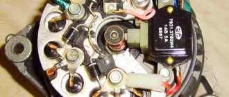
No generator can do without a rectifier unit and a voltage regulator. In this case, significant current flows through the valves and they are damaged. How is it better than the standard six? GENERATOR VAZ 2101 BATTERY CHARGING LAMP AND PRINCIPLE OF OPERATION
Read more: Measuring electrical laboratories
Generator operation
When the rotor begins to rotate, some voltage appears at the generator output. And it is supplied to the excitation winding through a control element. It is also worth noting that the generator set output is connected directly to the battery. Therefore, voltage is constantly present on the excitation winding. When the rotor speed increases, the voltage at the generator set output begins to change. A voltage regulator relay from a Valeo generator or any other manufacturer is connected to the generator output.
In this case, the sensor detects the change, sends a signal to a comparing device, which analyzes it, comparing it with a given parameter. Next, the signal goes to the control device, from which it is supplied to the actuator. The regulatory body is able to reduce the value of the current that flows to the rotor winding. As a result, the voltage at the generator set output is reduced. In a similar way, the mentioned parameter is increased in the event of a decrease in rotor speed.
Two-level regulators
A two-level automatic control system consists of a generator, a rectifier element, and a battery. It is based on an electric magnet, its winding is connected to the sensor. The driving devices in these types of mechanisms are very simple. These are ordinary springs. A small lever is used as a comparison device. It is mobile and makes switching. The actuator is the contact group. The control element is a constant resistance. Such a generator voltage regulator relay, the diagram of which is given in the article, is very often used in technology, although it is morally outdated.
Electronic regulator
Two-level mechanical voltage regulators have a big drawback - excessive wear of the elements. For this reason, instead of an electromagnetic relay, semiconductor elements operating in key mode began to be used. The operating principle is similar, only the mechanical elements are replaced by electronic ones. The sensing element is made on a voltage divider, which consists of constant resistors. A zener diode is used as a driving device.
The modern relay-voltage regulator of the VAZ 21099 generator is a more advanced device, reliable and durable. The executive part of the control device operates on transistors. As the voltage at the generator output changes, the electronic switch closes or opens the circuit, and additional resistance is connected if necessary. It is worth noting that two-level regulators are imperfect devices. Instead, it is better to use more modern developments.
Operation of a two-level regulator
When the generator operates, a voltage appears at the output, which is supplied to the winding of the electromagnetic relay. In this case, a magnetic field arises, with its help the lever arm is attracted. The latter is acted upon by a spring, which is used as a comparing device. If the voltage becomes higher than expected, the contacts of the electromagnetic relay open. In this case, a constant resistance is included in the circuit. Less current is supplied to the field winding. The voltage regulator relay for the VAZ 21099 generator and other domestic and imported cars operates on a similar principle. If the voltage at the output decreases, then the contacts are closed, and the current strength changes upward.
Generator device
The design of a car generator implies the presence of its own rectifier and control circuit. The generating part of the generator, using a stationary winding (stator), generates three-phase alternating current, which is then rectified by a series of six large diodes and the direct current charges the battery. Alternating current is induced by the rotating magnetic field of the winding (around the field winding or rotor). Next, the current is supplied to the electronic circuit through the brushes and slip rings.
Generator structure: 1.Nut. 2. Washer. 3.Pulley 4.Front cover. 5. Distance ring. 6.Rotor. 7.Stator. 8.Back cover. 9.Casing. 10. Gasket. 11.Protective sleeve. 12. Rectifier unit with capacitor. 13. Brush holder with voltage regulator.
The generator is located at the front of the car engine and is started using the crankshaft. The connection diagram and operating principle of a car generator are the same for any car. There are, of course, some differences, but they are usually associated with the quality of the manufactured product, the power and the layout of the components in the motor. All modern cars are equipped with alternating current generator sets, which include not only the generator itself, but also a voltage regulator. The regulator equally distributes the current in the excitation winding, and it is due to this that the power of the generator set itself fluctuates at a time when the voltage at the power output terminals remains unchanged.
New cars are most often equipped with an electronic unit on the voltage regulator, so the on-board computer can control the amount of load on the generator set. In turn, on hybrid cars the generator performs the work of the starter-generator; a similar circuit is used in other designs of the stop-start system.
The principle of operation of a car generator
Connection diagram for the VAZ 2110-2115 generator
The alternator connection diagram includes the following components:
- Battery.
- Generator.
- Fuse block.
- Ignition.
- Dashboard.
- Rectifier block and additional diodes.
The principle of operation is quite simple: when you turn on the ignition, the plus goes through the ignition switch through the fuse box, the light bulb, the diode bridge and goes through the resistor to the minus. When the light on the dashboard lights up, then the plus goes to the generator (to the excitation winding), then during the process of starting the engine, the pulley begins to rotate, the armature also rotates, due to electromagnetic induction, electromotive force is generated and alternating current appears.
The most dangerous thing for the generator is the short circuit of the heat sink plates connected to the “ground” and the “+” terminal of the generator by metal objects accidentally falling between them or conductive bridges formed by contamination.
Next, the diode passes plus into the rectifier block through a sine wave into the left arm, and minus into the right arm. Additional diodes on the light bulb cut off the negatives and only positives are obtained, then it goes to the dashboard assembly, and the diode that is there allows only the negative to pass through, as a result the light goes out and the positive then goes through the resistor and goes to the negative.
The principle of operation of a car DC generator can be explained as follows: a small direct current begins to flow through the excitation winding, which is regulated by the control unit and is maintained by it at a level of slightly more than 14 V. Most generators in a car are capable of generating at least 45 amperes. The generator operates at 3000 rpm and above - if you look at the ratio of the size of the fan belts for the pulleys, it will be two or three to one in relation to the engine frequency.
To avoid this, the plates and other parts of the generator rectifier are partially or completely covered with an insulating layer. The heat sinks are combined into a monolithic design of the rectifier unit mainly by mounting plates made of insulating material, reinforced with connecting bars.
Next, let's look at the connection diagram for a car generator using the example of a VAZ-2107 car.
Three-level regulation system
The quality of regulation of such structures is much higher than that of those previously discussed. Previously, mechanical designs were used, but today non-contact devices are more common. All elements used in this system are the same as those discussed above. But the operating principle is slightly different. First, voltage is applied through a divider to a special circuit in which information is processed. It is possible to install such a generator voltage regulator relay (Ford Sierra can also be equipped with similar equipment) on any car if you know the device and connection diagram.
Here the actual value is compared with the minimum and maximum. If the voltage deviates from the value that is set, then a certain signal appears. It is called a mismatch signal. It is used to regulate the current flowing to the excitation winding. The difference from a two-level system is that there are several additional resistances.
Is it possible to make a regulator with your own hands?
An example is considered on the regulatory mechanism for a scooter. The main nuance is that for correct operation the generator unit will need to be disassembled. A separate conductor must lead out the ground cable. The device is assembled according to the circuit of a single-phase generator.
Algorithm of actions:
- The generating set is disassembled and the stator element is removed from the scooter motor.
- There is ground around the windings on the left; it needs to be desoldered.
- Instead, a separate cable for winding is soldered. Then this contact is brought out. This conductor will be one end of the winding.
- The generator device is being reassembled. These manipulations are carried out so that two cables come out of the unit. They will be used.
- Then a shunt device is connected to the resulting contacts. At the final stage, the yellow cable from the old relay is connected to the positive terminal of the battery.
Modern voltage regulation systems
If the voltage regulator relay for the generator of a Chinese scooter is two-level, then more advanced devices are used on expensive cars. Multilevel control systems can contain 3, 4, 5 or more additional resistances. There are also tracking automatic control systems. In some designs, you can refuse to use additional resistances.
Instead, the frequency of operation of the electronic key increases. It is simply impossible to use circuits with electromagnetic relays in servo control systems. One of the latest developments is a multi-level control system that uses frequency modulation. In such designs, additional resistances are required, which are used to control logic elements.
What types of devices are common?
The simplest design is considered to be a two-level regulator. It consists of a generator, rectifier and battery. The winding of the electric magnet underlying the control device is connected in this case to the sensor. An ordinary spring is used here as a setting device, and a small lever plays the role of a comparing device (switching). The contact group works as an actuator. Constant resistance is a control element. Despite the outdated design of this relay-regulator, this design is still quite common.
The operation of a two-level regulator occurs as follows. The voltage that appears at the output of the generator is supplied to the relay winding. The resulting electromagnetic field attracts the arm of the lever, which is acted upon by the spring of the comparison device. When a voltage exceeds the specified parameters, the relay contacts open and a direct current enters the electrical circuit, the level of which is much lower. Accordingly, when the voltage decreases, the relay contacts close, causing the current to begin to increase.
Since the above two-level regulators are characterized by excessive wear of mechanical elements, modern voltage regulators began to use semiconductors acting as switches instead of an electromagnetic relay of this type. In this case, the very principle of operation of the relay regulators has not changed, however, the replacement of mechanical parts with radio-electronic ones is accompanied by the fact that the sensitivity of the voltage divider, made on constant resistors, has increased significantly. In addition, a zener diode is used as a master device.
Modern generator voltage regulators, used, for example, in domestic cars, are quite reliable and durable devices. In them, the executive part operates on semiconductor transistors. In addition, at the output of the generator after the electronic switch, which acts as a switch, if necessary, additional resistance can be connected.
It should be noted that the operating efficiency of three-level voltage regulation designs is noticeably improved. Despite their general fundamental similarity with mechanical two-level relay regulators, there are still differences. In them, information about the voltage level at the output of the generator is processed through a divider to a special circuit. Any car can be equipped with such regulators. In this case, it is only important to understand its structure and connection diagram.
In three-level voltage relay regulators of generators, its current indicator is compared with extreme (min and max) values. In this case, when the voltage level deviates from the specified parameters, a mismatch signal is generated, which affects the regulation of the current strength on the rotor field winding. In addition, the circuit of such a regulator implies the presence of several additional resistances located after the electronic key.
You should know that modern voltage regulation systems on expensive cars use more advanced multi-level devices that contain three or more additional resistances in their circuits. In addition, they can use tracking control systems. And in some car models, instead of additional resistances, the principle of increasing the frequency of key operation is used. Recent developments in multi-level control systems are based on frequency modulation. In them, additional resistances control the logical elements of the structure.
How to remove the relay regulator
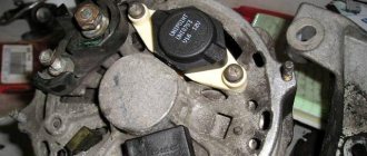
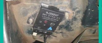
Removing the generator voltage regulator relay (“Lanos” or domestic “nine” is not important) is quite simple. It is worth noting that when replacing the voltage regulator, you only need one tool - a flat-head or Phillips screwdriver. There is no need to remove the generator or the belt and its drive. Most of the devices are located on the back cover of the generator, and are combined into a single unit with a brush mechanism. The most common breakdowns occur in several cases.
Firstly, when completely erasing the graphite brushes. Secondly, in case of breakdown of a semiconductor element. How to check the regulator will be discussed below. When removing, you will need to disconnect the battery. Disconnect the wire that connects the voltage regulator to the generator output. By unscrewing both mounting bolts, you can pull out the device body. But the voltage regulator relay for the VAZ 2101 generator has an outdated design - it is mounted in the engine compartment, separately from the brush assembly.
Replacing the unit
It is not difficult to remove the generator from the classic Zhiguli model. But it is mounted at the bottom of the engine compartment, under the engine, and must be removed from below. This means that you will need an inspection hole or overpass. The preparatory operation consists of placing the car in a pit and removing the engine crankcase protection, if any. It is also necessary to open the hood and remove the negative ground terminal of the battery. Now everything is ready for removal.
The work is performed in the following order. Disconnect the generator of your VAZ 2101 from the vehicle's electrical system. Unscrew the nut securing the positive wires to the generator. Disconnect the brush connector and the diode bridge connector.
Unscrew the nut securing the unit to the adjustment bar a couple of turns. If possible, use a socket head and an extension with a universal joint. Tilt the generator so that the belt sags on the pulleys of the crankshaft, water pump and VAZ 2101 generator. Remove the belt.
Go down into the pit. Using a 19 mm wrench, unscrew the large fastening nut. The bolt that secures the unit is located at the very bottom of the engine compartment and is exposed to wind and water, snow and dirt, so it often sticks. Knock it out with a hammer. Carefully remove the generator from the VAZ 2101.
If repairs are expected, proceed to it. Replacement is planned - mount the generator on your VAZ 2101 in the reverse order. To connect, connect the plugs and tighten the nut securing the wires.
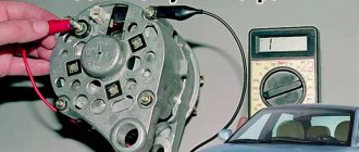
Device check
The relay-regulator of the voltage of the VAZ 2106 generator, “kopecks”, and foreign cars is checked equally. As soon as you remove it, look at the brushes - they should be more than 5 millimeters long. If this parameter is different, the device must be replaced. To carry out diagnostics, you will need a constant voltage source. It would be desirable to be able to change the output characteristic. You can use a battery and a couple of AA batteries as a power source. You also need a lamp, it must run on 12 Volts. You can use a voltmeter instead. Connect the plus from the power supply to the voltage regulator connector.
Accordingly, connect the negative contact to the common plate of the device. Connect a light bulb or voltmeter to the brushes. In this state, voltage should be present between the brushes if 12-13 Volts are supplied to the input. But if you supply more than 15 Volts to the input, there should be no voltage between the brushes. This is a sign that the device is working properly. And it doesn’t matter at all whether the voltage regulator relay of the VAZ 2107 generator or another car is diagnosed. If the control lamp lights up at any voltage value or does not light up at all, it means that there is a malfunction of the unit.
Checking and replacing the voltage regulator relay VAZ 2107
You can also check the relay regulator in a garage, but this will require several tools. Here they are:
- household multimeter (the accuracy level of the device must be at least 1, and the scale must be up to 35 volts);
- open-end wrench 10;
- flat screwdriver.
A simple option for checking the regulator
First of all, the relay regulator must be removed from the car. This is not difficult to do; it is secured with just two bolts. In addition, during the test you will have to actively use the battery, so it must be fully charged.
- The car engine starts, the headlights turn on, after which the engine idles for 15 minutes (the crankshaft rotation speed should not exceed 2 thousand revolutions per minute);
- The hood of the car is opened, and the voltage between the battery terminals is measured using a multimeter. It should not exceed 14 volts, and should not be lower than 12 volts.
The voltage between the terminals is within normal limits - If the voltage does not fall within the above range, this clearly indicates a breakdown of the relay regulator. This device cannot be repaired, so the driver will have to change it.
A difficult option for checking the regulator
This option is used in cases where the failure of the regulator cannot be determined in a simple way when checking (for example, in situations where the voltage between the battery terminals is not 12 volts or higher, but 11.7 - 11.9 volts). In this case, the regulator will have to be removed and “ringed” it using a multimeter and a regular 12-volt light bulb.
- The VAZ 2106 regulator has two outputs, which are designated “B” and “C”. These contacts are supplied with power from the battery. There are two more contacts that go to the generator brushes. The lamp is connected to these contacts as shown in the figure below.
If the lamp does not light in any of the three options, it’s time to change the regulator - If the voltage at the outputs connected to the power supply does not exceed 14 volts, the light between the brush contacts should light up brightly.
- If the voltage at the power outputs using a multimeter increases to 15 volts or higher, the lamp in a working regulator should go out. If it does not go out, the regulator is faulty.
- If the light does not light up in either the first or second case, the regulator is also considered faulty and needs to be replaced.
Video: checking the relay regulator on a classic
conclusions
In the electrical system of a car, the voltage regulator relay of the Bosch generator (as, indeed, of any other company) plays a very important role. Monitor its condition as often as possible and check for damage and defects. Cases of failure of such a device are not uncommon. In this case, in the best case, the battery will be discharged. And in the worst case, the supply voltage in the on-board network may increase. This will lead to the failure of most electricity consumers. In addition, the generator itself may fail. And its repair will cost a tidy sum, and considering that the battery will fail very quickly, the costs will be astronomical. It is also worth noting that the Bosch generator voltage regulator relay is one of the leaders in sales. It has high reliability and durability, and its characteristics are as stable as possible.
Tips for increasing the service life of the relay regulator
To prevent rapid failure of the regulatory device, you must adhere to several rules:
- Do not allow the generator set to become heavily contaminated. From time to time you should perform a visual diagnosis of the device's condition. In case of serious contamination, the unit is removed and cleaned.
- The tension of the drive belt should be checked periodically. If necessary, it is stretched.
- It is recommended to monitor the condition of the generator set windings. They should not be allowed to darken.
- It is necessary to check the quality of contact on the control cable of the regulatory mechanism. Oxidation is not allowed. When they appear, the conductor is cleaned.
- Periodically, you should diagnose the voltage level in the electrical network of the car with the engine running and switched off.
Remote controller
ATTENTION! A completely simple way to reduce fuel consumption has been found! Don't believe me? An auto mechanic with 15 years of experience also didn’t believe it until he tried it. And now he saves 35,000 rubles a year on gasoline! Read more"
This often happens to drivers. The brushes of the generating device burn out. The regulator is built in along with the brushes. We have to change everything together. And here’s some advice from experts: it’s better to install an external regulator than a built-in one. The models released recently have not been praised very much.
Okay, do you think I’ll install an external one, but how do I connect it? It turns out that there is a convenient scheme that makes it easy to carry out all this modernization.
Some important points:
- do not confuse the chips on the regulator numbered 67 and 15 (the first should be connected to the generating device, and the second should go to the fuses);
This is what the connection diagram looks like
In the lower photo we see a diagram that shows the connection of the already built-in regulator relay.
It is suitable for connecting to “fives”, “sevens”, VAZ 2104, if the PG is installed from a VAZ “kopek”. As you can see, the remote-type regulator relay is connected via two terminals. Pin 15 goes to the fuse.
The second pin 67 is connected to the generator. The wire is connected to the brush chip.
Also, the remote-type relay must be connected to ground - any part of the body.
A relay is nothing more than a switch that serves to close and disconnect individual zones of an electrical circuit that occur at specific electrical values. A machine relay is otherwise called a load voltage switch, and this is 100 percent true. When the power supply unit, fan or starter consumes more current than necessary, the relay trips.
The relay consists of an electric type magnet, an armature and a switch. In this case, the electromagnet is a cable twisted around an inductor with a magnetic rod, and the armature is a special plate that controls the contacts.
As soon as electrical voltage passes through the magnet winding, an electric field is created. A special pusher presses the armature against the core and, thereby, the contacts switch.
Attention. There are two types of relays used on VAZ cars. This is a non-contact relay-regulator and MER (electric). It is the diagram of the last relay that is shown in the picture below.
The non-contact relay or NERR is a fairly new unit that does not require any additional adjustments or regulation. As for the MED, this is an old-style device, the production of which has currently been suspended.
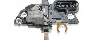
So, the BRN or built-in regulator is a device consisting of a microcircuit, a transistor and a housing with brushes. If the built-in regulator fails, it is replaced with a new one, or an external one is installed.
The external regulator is easy to install if you strictly follow the instructions.
Modernization involves dismantling and disassembling the generating device.
Independent connection of the relay regulator to the generator’s on-board network (step-by-step instructions)
When installing a new control device, the following points must be taken into account:
- Before performing the task, it is necessary to diagnose the integrity and reliability of the contacts. This is a cable that runs from the vehicle body to the generator set housing.
- Then connect terminal B of the regulatory element to the positive contact of the generating set.
- It is not recommended to use twisted wires when making connections. They overheat and become unusable after a year of use. Soldering should be used.
- It is recommended to replace the standard conductor with a wire whose cross-section is at least 6 mm2. Especially if, instead of the factory generator, a new one is installed, which is designed to operate under current conditions above 60 A.
- The presence of an ammeter in the generator-battery circuit allows you to determine the power of power sources at a specific time.
Remote controller connection diagram
Connection diagram for remote type devices
This device is installed after the wire into which it will be connected is determined:
- In older versions of Gazelles and RAF, mechanisms 13.3702 are used. They are made in a metal or polymer case and are equipped with two contact elements and brushes. It is recommended to connect them to the negative open circuit; the outputs are usually marked. The positive contact is taken from the ignition coil. And the output of the relay is connected to the free contact on the brushes.
- VAZ cars use devices 121.3702 in a black or white case; there are also double modifications. In the latter, if one of the parts breaks down, the second regulator will remain working, but you need to switch to it. The device is installed in the open circuit of the positive circuit with terminal 15 to the contact of the B-VK coil. The conductor number 67 is connected to the brushes.
In newer versions of the VAZ, the relays are installed in the brush mechanism and connected to the ignition switch. If the car owner replaces the standard unit with an AC unit, then the connection must be made taking into account the nuances.
More details about them:
- The need to fix the unit to the vehicle body is determined by the car owner independently.
- Instead of a positive output, contact B or B+ is used here. It must be connected to the car's electrical network via an ammeter.
- Remote type devices are usually not used in such cars, and built-in regulators are already integrated into the brush mechanism. There is one cable coming from it, designated D or D+. It must connect to the ignition switch.
In cars with diesel engines, the generator unit can be equipped with output W - it is connected to the tachometer. This contact can be ignored if the unit is installed on a gasoline modification of the car.
User Nikolay Purtov spoke in detail about installing and connecting remote devices to a car.
Checking the connection
The engine must start. And the voltage level in the car’s electrical network will be controlled depending on the number of revolutions.
Perhaps, after installing and connecting a new generator device, the car owner will encounter difficulties:
- when the power unit is activated, the generator unit starts, the voltage value is measured at any speed;
- and after the ignition is turned off, the vehicle engine runs and does not turn off.
The problem can be solved by disconnecting the excitation cable, only then will the engine stop.
The engine may stall when the clutch is released and the brake pedal is pressed. The cause of the malfunction is residual magnetization, as well as constant self-excitation of the unit winding.
To avoid this problem in the future, you can add a light source to the gap in the exciting cable:
- the light will light when the generator is turned off;
- when the unit starts, the indicator goes out;
- the amount of current that passes through the light source will not be sufficient to excite the winding.
The Altevaa TV channel talked about checking the connection of the regulatory device after connecting the motorcycle to a 6-volt network.
GU or generator
The generator in any automotive electrical circuit performs the dominant functions. The normal functioning and operation of the machine depends on it. Reliable PG is installed in all foreign cars and models of the domestic automobile industry.
For example, a GU is placed on the “six”, the charge of which satisfies the need for electricity of any standard component. If you do not overload the generating device of the “six”, then the car is capable of driving many, many more kilometers. However, it is important to carry out preventive procedures in a timely manner - monitor the belt tension and the condition of the brushes.
The GU is connected according to the classical scheme. Using the VAZ 2106 generator as an example, let’s consider its functioning. This GU is marked as G-221. It is an AC synchronous electric machine with ELMG excitation. A VB (rectifier) with 6 diodes is built inside the GU.
| 1 | generator rotor winding |
| 2 | generator |
| 3 | generator stator winding |
| 4 | generator rectifier |
| 5 | accumulator battery |
| 6 | ignition switch |
| 7 | battery charge indicator lamp |
| 8 | battery warning light relay |
| 9 | fuse box VAZ -2106 |
| 10 | throttle |
| 11 | temperature compensation resistor |
| 12 | additional resistors |
| 13 | voltage regulator |
A simple and understandable scheme that does not require any subtleties or specific knowledge. On the “six” the PG is located on the engine on the right. It is attached to the tension bar with a nut and to the bracket with its claws.
As you can see, the diagram shows an external regulator. It is marked with the number 13. The generator is indicated with the number 2, the fuse box is indicated with the number 9.
Removing and installing the voltage regulator
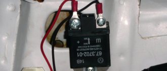
Replacing the external voltage regulator VAZ 2101-2106
1) Using the “8” socket, unscrew the two nuts and remove the regulator.
2) Disconnect the two wires.
3) Attach the new regulator to the mudguard and connect the wires: orange to terminal “15”, and gray to terminal “67”.
Voltage regulator relay connection diagram
ATTENTION! Before starting the engine, make sure that the contact between the voltage regulator housing and the vehicle ground is reliable, and that the wires to terminals “15” and “67” are connected correctly.
How to check the pH on a VAZ-2110 without removing it
If you find at least one of the listed signs, do not be lazy to check the voltage regulator on your VAZ-2110. This procedure will not take more than 10 minutes. To do this, you will need a voltmeter or multimeter turned on in its mode, as well as an assistant. The verification procedure is as follows:
- We start the car engine and warm it up to operating temperature.
- Without turning off the engine, we connect one voltage probe of the generator, and the second to the “ground” of the device.
- We ask the assistant to turn on the low beam headlights and press the accelerator pedal, keeping the speed at 2000-2500 thousand rpm.
- We measure the voltage with the device.
For the VAZ-2110, the voltage regulator should produce 13.2-14.7 V. This is the norm. If the voltmeter readings differ from those shown, diagnostic measures should be continued.