Hello. Share a diagram of the parts and devices located under the hood.
- How to glue the hood reinforcement on a VAZ 2115? – 3 answers
- The amplifier has come off the hood of a VAZ 2115 - 3 answers
- Snow gets under the hood of a VAZ 2114 – 2 answers
- VAZ 2114 fuse diagram – 1 answer
- Icons on the instrument panel of the VAZ 2114 – 1 answer
In the center there is a motor, into which air flows through the receiver from the air filter, which is to the right of the engine. To the left of the engine is the windshield washer reservoir. The brake system hydraulic reservoir is located near the air duct above the air filter. The battery is in the lower right corner. The engine cooling system tank is installed slightly higher. The gearbox is located under the engine, under the right side.
Subscribe
to our channel in
Index.Zen
Even more useful tips in a convenient format
For the efficient operation of the injection power unit, the VAZ-2114 car system includes a large number of different mechanisms and automated devices. You can’t say that the “fourteenth” car is filled to capacity with electronics, but if you look under the hood, you can find all kinds of VAZ-2114 8-valve injector sensors.
The main purpose of electronics is to monitor the condition of vehicle components and assemblies. The received data is transmitted to the main “brain” center of the car. Thanks to this approach, the driver no longer needs to spend a long and exhausting time looking for reasons for deviations from the operation of a particular system. The ECU will provide all the information. What sensors are involved in the operation of the VAZ-2114 and where are they located?
General information about VAZ-2114 sensors
Sensors look like small mechanisms. However, their role in the operation of the entire vehicle system is simply colossal. They signal the remaining fuel in the gas tank, inform the driver of the coolant temperature, and determine the position of various engine elements in a certain operating mode. In order to know your car well and understand what could fail in a given situation, you need to know the entire list of mechanisms involved in the system.
We list all the sensors on the VAZ-2114 injector 8 valves, which are the most important:
- Crankshaft positions.
- TPDZ.
- Camshaft position sensor.
- DTOZH.
- Speed.
- Idle move.
- DMRV.
- Lambda probe.
These devices are in most cases located in the engine compartment. Almost all of them are installed at the factory during vehicle assembly. But the driver himself can install some sensors at any suitable time. It is also important to know how each of these devices works and what primary task it performs.
VAZ 2110 engine compartment description
Dear visitors of the “Cars” website! We will be very grateful for your comments on the video clip “VAZ 2110 engine compartment description”; registration is not required for this. We also ask you to let us know if you have any problems playing the video.
Great
But why is it not possible to pull out the whole bunch? My car stalled and wouldn’t start, 21114 124, the state first showed 0328, then it disappeared and started showing 1602, 0338, 0340. I wanted to pull the whole bunch, but there it was. What should I do? I'm guilty of damage at the bottom, where the beam enters the torpedo, I can't reach it with my hands
Don't interfere with the machine's work
very informative. Keep stopping them from working. This is the most interesting thing. Stop something from working
how can I contact you I need your advice if possible call me from me subscribe 79780067322 my name is Evgeniy
Great job, accessible and understandable. We still have a lot of people repairing their iron bunks on their own. A good addition to the repair manual on your channel. Thank you.
romanysh has whatsapp
Thank you so much, thank you so HUGEly Cool video This is exactly the topic I needed, All that’s left is to find a warm garage so that it would be normal to work with electrical tape Romanych, well done, thanks again
Crankshaft position sensor
You can often hear drivers with many years of experience calling this mechanism nothing other than a synchronization sensor. This name comes from the principle of operation of the device. The tasks of the DPKV are to synchronize the operation of the electronic unit and the gas distribution mechanism.
The VAZ-2114 is equipped with an inductive type DPKV. The cost of such a sensor is relatively small. If a vital controller for a car fails, most drivers prefer to immediately replace the device with a new one.
If the DPKV breaks down, further operation of the vehicle will become impossible. Without this mechanism, the fuel supply system will stop working, because the ECU will not receive information about when it is necessary to give a command to inject fuel into the cylinders. The location of the DPKV is in close proximity to the camshaft.
Electronics are responsible for fuel delivery in the VAZ-2114 car system. Without TPS, the control unit will not be able to determine the optimal time to supply gasoline. Deviations from the correct operation of the TPS lead to an increase in the amount of fuel consumed. The operation of many other car systems depends on the angle at which the remote control is located: cooling, fuel supply.
see also
The TPS is located near the idle speed sensor. In the “fourteenth” system, the work of these two devices is closely linked.
When the TPS breaks down, the car begins to twitch in a certain position of the damper, and instability of engine operation is also noted. All VAZ-2114 8 valve sensors are interconnected in their operation, so two different devices sometimes exhibit the same symptoms of malfunction. If symptoms of a breakdown occur, it is necessary to take a comprehensive approach to checking all controllers.
Schematic electrical diagram.
Features of replacing the driveshaft crosspiece of a VAZ-2107: 3 important tips for choosing a part
The schematic diagram retains the sequence and structure of the block diagram, but instead of general functional blocks, the full composition of the elements of the device (device) is shown, depicted in the form of conventional graphic symbols
. Each part is depicted with the number of pins that real parts have, and the connections between the pins are shown in such a way that you can trace all the circuits and connections in detail, and easily understand the processes taking place and the principle of operation of the device.
For ease of reading, next to the symbolic image of the part its alphanumeric designation
, which defines information about the part: functional purpose, location and marking in the diagram. Alphanumeric designations are indicated in abbreviated form and consist of a certain number of letters of the Latin alphabet and Arabic numerals, written sequentially, on one line and without spaces.
Letter designation
taken from the name of the part and indicated by one or two first letters, for example,
R
- resistor,
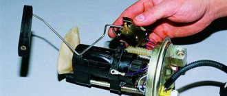
C
- capacitor,
VD
- diode,
VT
- transistor,
SA
- switch,
XP
- two-pole plug,
EL
- lighting lamp, etc.
Digital designation
indicates the serial number of parts of the same type in the circuit, for example,
R1
,
R2
,
R3
, etc., or
VD10
,
VD11
, etc.
Let's draw a schematic electrical diagram of a table lamp, and for ease of reading the diagram, at the first stage, we will highlight its main elements with green rectangles.
Looking at the diagram, we can say that to power the table lamp, an alternating voltage of 220 V is used, which is supplied through the XP1
and switch
SA1
is supplied to light bulb
EL1
.
That all elements are designed for an operating alternating voltage of 220 V, and that the operation of the lamp is carried out by the position of the contact of the switch SA1
: when the contact is closed, the lamp
EL1
lights up, when it opens, it goes out.
From the diagram it can be seen that the upper terminal of the XP1
connected to the left terminal of the switch
SA1
, the right terminal of the switch contact is connected to the upper terminal of the light bulb
EL1
, and the lower terminal of the light bulb is connected to the lower terminal of
the XP1
.
Switch contact SA1
is shown in an open state, which corresponds to its initial position and the off state of the table lamp. The electrical connection between the terminals of the elements is depicted by segments of horizontal and vertical lines.
And at the same time, the circuit diagram does not give us a complete picture of the table lamp, since it does not indicate information about the design of the lamp and the dimensions of the parts. The fact is that when studying the principle of operation, there is no need to know how, for example, the light bulb is made (size and shape of the bulb, type and size of the base, coil resistance, etc.), what design the switch or plug has
If all this information were indicated on the diagram, they would only distract attention to unnecessary details that are not of fundamental importance
But still, to expand the functionality, some part of the design data of the elements (power, type, method of connection) is indicated on the circuit diagrams, because in some cases it turns out to be the main and only document that is used to guide the manufacture, adjustment, maintenance and repair of equipment.
If we compare the structural and circuit diagrams, then what they have in common is the order of arrangement of the elements and the path of the signal (in our case, electric current), which goes from left to right, i.e. in the direction familiar to ordinary reading. However, on circuit boards, chassis or panels of real devices, elements may be arranged differently, subject to rules aimed at minimizing parasitic connections between individual elements, nodes, and blocks. Therefore, the arrangement of elements inside a real device may not correspond to the circuit diagram.
The considered structural and circuit diagrams are intended mainly for studying the principle of operation, and depending on the type, they provide a visual representation of the functional or elemental structure. To have an idea of the design of the table lamp, the approximate arrangement of the elements and methods of connection between them, use the connection diagram
or
wiring diagram
.
Camshaft position sensor
This mechanism is located near the cylinder block. The main task is to transmit data to the ECU regarding the current operating cycle. Among specialists, the mechanism is called a Hall sensor. The operation of the device is based on the following principle: in accordance with the location of the crankshaft, the position of the gas distribution mechanism is determined. The data received by the sensor is reported to the electronic unit. Fuel is injected and the mixture is subsequently ignited.
Steering
To move normally in a car, the driver needs to make turns, U-turns or detours, that is, deviate from straight-line movement, or simply control his car so that it does not drift to the side. For this purpose, its design provides steering control. This is one of the simplest mechanisms in a car. Let's look at the names of some of the elements below. The steering system consists of:
These devices consist of a steering system that is connected to the front wheels by steering and brakes.
Modern cars use an additional element - power steering, which allows the driver to use less force to turn the steering wheel. It comes in the following types:
Knock sensor, DTOZH, speed and others
In addition to the above mechanisms, other very important devices can be found in various corners of the engine compartment. The location of the VAZ-2114 injector sensors is quite chaotic, some are located directly on the power unit, others in other places - the gearbox, on electrical circuits.
Some equally important mechanisms include:
- The knock sensor is sensitive to various engine vibrations. Based on the received pulses, the ECU determines the qualitative composition of the mixture. Located on the cylinder block.
Engine temperature sensor - the only and simple, but extremely important task assigned to this device is to monitor the coolant temperature.
Speed sensor – from the name itself it is clear that this controller is necessary to measure the speed of a car. The DS transmits impulses to the ECU, which processes them and determines the speed of the car; the resulting result is displayed on the instrument panel by the speedometer.
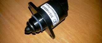
Idling speed – not only reads information, but also corrects engine operation. DXH, using a special needle, controls the pipe - closes and opens. Due to this, the amount of oxygen supplied to the throttle assembly changes.
Mass air flow sensor - reads the data and transmits it to the control unit, which, based on the information received, determines the optimal ratio of the various components of the fuel-air mixture. A breakdown of the air flow sensor leads to the fact that the car significantly loses power, and the driver begins to feel a significant increase in the amount of gasoline consumed by the car.
Sanding chips before painting
If you decide not to remove all the old paint, but only to update the hood, you need to very carefully remove and treat the places where the stones are chipped.
There are always a lot of them on the hood, because this is one of the most vulnerable places of the car. The chipping area must be covered with masking tape. And only after this the treatment is carried out: washed, dried and treated with a degreasing liquid. After this, we clean the edges of the chips with coarse sandpaper and remove the rust. Then you should clean the chipped area with a brush, rinse thoroughly and treat again with a degreaser.
If the scratch is deep, then it must be puttied. You can use regular aluminum putty. After drying, the treated area is sanded. Application of primer is not necessary when using this putty.
Before painting, we matte the entire remaining part of the hood (rubbing off the glossy layer). And after that we move on to the standard painting procedure, which is described below.
Car modifications 2114
VAZ-21140 . Modification with an 8-valve injection engine VAZ-2111, 1.5 liters and 77 horsepower. Serial production from 2003 to 2007
VAZ-21144 . Modification with an 8-valve VAZ-21114 engine, 1.6 liters and 81.6 horsepower. Years of serial production: 2007-2013.
VAZ-211440 . Another modification released in 2007, it was equipped with a VAZ-11183 engine with a volume of 1.6 liters and a power of 82 horsepower. The car was discontinued in 2013.
VAZ-211440-24 . Released in 2009, a modification with an injection 16-valve VAZ-21124 engine with a volume of 1.6 liters and a power of 89.1 horsepower. Discontinued in 2013.
VAZ-211440-26 . Modification with a 16-valve injection engine VAZ-21126, which complies with the Euro-3 environmental standard, with a volume of 1.6 liters and a power of 98 hp. The car was produced from 2010 to 2013.
What is under the hood of the VAZ 2113
I think it is important that the car looks beautiful not only from the outside, but also from the inside. I mean what's under the hood
I’m not talking about technical characteristics, everyone has their own power and their own parameters, some drove a herd of horses there, and some a small pony, but this pony needs to look great. What is under the hood of the VAZ 2113?
There are parts that need care and attention. I'm planning to install a new receiver soon, it will be slightly larger
Since the car is still in the garage and is ready for all sorts of experimental actions, I cut out a place in the frame there. Then it turned out that I had to abandon what I had started a little, unforeseen worries, you know.
After some time, I returned to the garage and continued what I had started, purchased a primer and applied a thin layer under the hood, let it dry, then painted it yellow. Why yellow, you ask, but I like this color, so sunny and vital, as if nothing under the hood will break. After painting I had to wait a couple more days for everything to dry thoroughly. It is worth noting that you need to select heat-resistant paint, because under the hood there is exposure to high temperatures, sometimes associated with the release of any liquids, such as oil or gasoline, so you need to select durable, special paint. I won’t advertise my paint, but I will say that during the entire run-in period it didn’t even change color, let alone slip. They frightened me with the fact that I would never pass a technical inspection in my life, it’s not true, I passed everything without any particular difficulties, I didn’t give anything to anyone, everything was fair and according to the law.
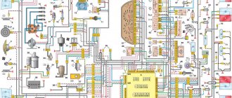
Wiring diagram VAZ-2114 for old models
Electrical diagram of car 2114: 1 - headlight; 2 [Installed on a part of the car] - fog lamp; 3 — ambient air temperature sensor; 4 — electric engine radiator fan; 5 — block for connection to the wiring harness of the engine control system; 6 — engine compartment lamp switch; 7 [Installed on a part of the car] - reserve block for connecting an audio signal with one terminal (the negative terminal is connected to the body); 8 — sound signal; 9 — liquid level sensor in the windshield washer reservoir; 10 [Installed on a part of the car] - brake pad wear sensor; 11 — low oil level sensor; 12 - generator; 13 [Installed on a part of the car] - engine compartment lamp; 14 — temperature indicator sensor; 15 — starter; 16 — battery; 17 [Installed on a part of the car] - relay for turning on fog lights; 18 — coolant level sensor in the expansion tank; 19 — sensor of insufficient brake fluid level; 20 — reversing light switch; 21 — windshield wiper gear motor; 22 — emergency oil pressure sensor; 23 — rear window washer electric pump; 24 — electric pump for windshield washer; 25 — instrument panel; 26 — mounting block of fuses and relays; 27 — brake signal switch; 28 — ignition relay; 29 - ignition switch (lock); 30 — glove box lighting lamp; 31 — switch for the glove compartment lighting lamp; 32 — rear window heating switch; 33 — rear fog light switch; 34 [Installed on a part of the car] - fog light switch; 35 - combined switch for side lights and headlights; 36 — alarm switch; 37 — steering column switches; 38 — brightness control for instrument lighting; 39 — illumination lamp for the headlight hydraulic adjustment control handle; 40 — socket for connecting a portable lamp; 41 — side direction indicator; 42 — interior lighting switch (front door open sensor); 43 — interior lamp; 44 — electric fan of the ventilation and heating system; 45 — additional resistor of the electric fan of the ventilation and heating system; 46 — switch for operating modes of the electric fan of the ventilation and heating system; 47 — illumination lamp for the handle of the operating mode switch of the electric fan of the ventilation and heating system; 48 — backlight lamp for the heater control unit; 49 — display unit of the on-board control system; 50 [Installed on part of the car] - trip computer; 51 — interior lighting switch (rear door open sensor); 52 [Installed on a part of the car] - block for connecting a clock; 53 — fuel module; 54 — ashtray illumination lamp; 55 — cigarette lighter; 56 — interior lamp; 57 — switch for the parking brake warning lamp; 58 — rear light; 59 — license plate light; 60 — additional brake light; 61 — heating element for heating the rear window; 62 — rear window wiper gear motor; A - numbers of pins in connecting blocks.
Metallic scraping noise when braking
Bandit cars of the 90s: list. popular cars of the 90s
We have already written about this above, but we should consider squeaking brakes in a little more detail. Brakes sometimes create a characteristic squeaking sound, especially if the pads are wet. Some types of brake pads (especially semi-metallic pads) can squeal or squeal even when they cool down during the winter season. If you hear metallic scraping noises when braking, like someone running a file over rough metal, your brake pads are worn out and your car needs brake service. You shouldn’t hesitate to do this and here’s why.
Worn brake pad
At low speeds, worn brakes work just as effectively, the only difference is an annoying sound. However, at medium and high speeds (50 km/h and above), such brakes may not work at all. In fact, if brakes that are badly worn are "switched on" at speed, there is a risk that the friction material left on the pads will separate from the backing plate. This will cause the brakes to fail and, pressing the pedal, the car will continue to move.
VAZ-2114 diagram (second option)
Electrical diagram of VAZ-2114 cars (without engine control system):
1 — block headlights; 2 — fog lights; 3 — air temperature sensor; 4 — electric motor of the engine cooling system fan; 5 — blocks connected to the wiring harness of the ignition system; 6 — engine compartment lamp switch; 7 — block for connecting to a single-wire type audio signal; 8 — sound signal; 9 — washer fluid level sensor; 10 — front brake pad wear sensor; 11 — oil level sensor; 12 - generator; 13 — engine compartment lamp; 14 — coolant temperature indicator sensor; 15 — starter; 16 - battery; 17 — relay for turning on fog lights; 18 — coolant level sensor; 19 — brake fluid level sensor; 20 — reverse light switch; 21 — windshield wiper gearmotor; 22 — oil pressure warning lamp sensor; 23 — block for connecting to the rear window washer electric motor; 24 — electric motor for windshield washer; 25 — instrument cluster; 26 — mounting block 2114; 27 — brake light switch; 28 — ignition relay; 29 — ignition switch; 30 — glove box lighting lamp; 31 — glove box lighting switch; 32 — rear window heating element switch; 33 — rear fog light switch; 34 — fog lamp switch; 35 — switch for external lighting lamps; 36 — alarm switch; 37 — steering column switches; 38 — switch for instrument lighting lamps; 39 — lamp for illuminating the headlight hydrocorrector scale; 40 — plug socket for a portable lamp; 41 — side direction indicators; 42 — lamp switch on the front door pillars; 43 — lamp for individual interior lighting; 44 — heater fan electric motor; 45 — additional resistor of the heater electric motor; 46 — heater fan switch; 47 — heater switch illumination lamp; 48 — lamp for illuminating the heater levers; 49 — on-board control system unit; 50 — trip computer; 51 — lamp switch on the rear door pillars; 52 — block for connecting the wiring harness of the engine control system; 53 — electric fuel pump and gasoline quantity sensor; 54 — front ashtray illumination lamp; 55 — cigarette lighter 2114; 56 — trunk lighting lamp; 57 — trunk light switch; 58 — interior lamp; 59 — parking brake warning lamp switch; 60 — rear external lights; 61 — rear internal lights; 62 — block for connection to the rear window heating element; 63 — license plate lights; 64 - additional brake signal located in the spoiler.
Conventional numbering of plugs in blocks:
Wiring diagram VAZ-2114 new models
The updated engine has a new injection scheme, so it was necessary to use some new devices, as well as replace the ignition coil with a more efficient one and adapted to Euro 3 conditions. In order to comply with them, the engine had to minimize the amount of CO at start-up. And for this it was necessary to lean the mixture. Since a lean mixture ignites worse, it needed a more powerful spark to spark. This explains the use of a coil of increased power.
- block headlights;
- gearmotors for headlight cleaners*;
- fog lights*;
- ambient temperature sensor;
- sound signals;
- engine compartment light switch;
- engine cooling fan electric motor;
- generator VAZ-2114;
- low oil level indicator sensor;
- washer fluid level sensor;
- front brake pad wear sensor;
- wire ends connected to the common windshield washer pump**;
- windshield washer pump;
- headlight washer pump*;
- wire ends for connecting to the rear window washer pump on VAZ-2113 and VAZ-2114 cars;
- low oil pressure indicator sensor;
- engine compartment lamp;
- wire lug for connecting to the engine management system wiring harness;
- windshield wiper gear motor;
- starter VAZ-2114;
- block connected to the wiring harness of the ignition system on carburetor cars;
- coolant temperature indicator sensor;
- reverse light switch;
- low brake fluid level indicator sensor;
- accumulator battery;
- low coolant level indicator sensor;
- relay for turning on fog lights;
- mounting block;
- brake light switch;
- plug socket for a portable lamp;
- hydrocorrector scale illumination lamp;
- parking brake indicator lamp switch;
- block for connecting a backlight lamp;
- switch for instrument lighting lamps;
- Understeering's shifter;
- hazard switch;
- front seat heating element relay;
- ignition switch;
- rear fog lamp circuit fuse;
- front seat heating elements circuit fuse;
- door lock circuit fuse;
- front ashtray illumination lamp;
- ignition relay;
- cigarette lighter VAZ-2114;
- glove box lighting lamp;
- glove compartment light switch;
- heater fan motor;
- additional heater motor resistor;
- heater fan switch;
- heater switch illumination lamp;
- heater lever illumination lamp;
- gear motors for electric windows of the front doors;
- right front door ESP switch (located in the right door);
- gear motors for locking front door locks;
- wires for connecting to the right front speaker;
- gear motors for locking rear doors;
- wires for connecting to the right rear speaker;
- door lock control unit;
- wires for connecting to radio equipment;
- headlight wiper switch*;
- rear window heating element switch;
- rear fog light relay;
- block for connection to the heating element of the right front seat;
- rear fog light switch;
- right front seat heating element switch;
- fog light switch*;
- switch for external lighting lamps;
- left front seat heating element switch;
- block for connection to the heating element of the left front seat;
- wires for connecting to the left front speaker;
- left front door power window switch (located in the left door);
- right front door power window switch (located in the left door);
- wires for connecting to the left rear speaker;
- side direction indicators;
- dome light switches on the front door pillars;
- dome light switches on the rear door pillars;
- lampshade VAZ 2114;
- individual interior lighting lamp;
- block for connecting to the wiring harness of the electric fuel pump;
- trunk light switch;
- instrument cluster;
- trunk light;
- on-board control system display unit;
- trip computer*;
- block for connecting the wiring harness of the engine management system;
- rear exterior lights;
- rear interior lights;
- pads for connecting to the rear window heating element;
- license plate lights;
- additional brake signal located on the spoiler.
Do it yourself lighting of the engine compartment on VAZ 2112, 2111, 2110
Many people are faced with the problem that domestic cars do not have engine compartment lighting. This phenomenon greatly disturbs the driver when the engine needs to be repaired at night and the parts are not visible at all. Naturally, a thought immediately arises. Often, many motorists had breakdowns at night and there was no lighting at all. In this case, you had to use flashlights or lighters, which were held in one hand, and the other hand needed to repair the part, which is not a very convenient way to repair.
Everything was done, but time and effort wasted. After such unforeseen situations on the roads at night, it is best to install backlighting on the VAZ 2112, 2111, 2110. So, the work begins.
This article will talk about installing backlighting with LED bulbs or regular halogen ones. To successfully complete the job, you need to have the following tools and materials.
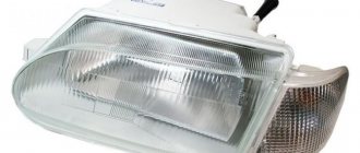
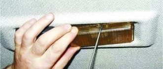
1. Engine compartment lamp from VAZ 2113 -2115 cars 1 pc. 2.Two-core wire, with a cross-section of 1 mm, approximately five meters long. 3.On and off button 1pc. 4. Hanging fuse 1 pc. 5. Flat fuse for five amperes 1 pc.
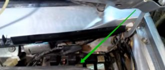
The installation begins. To install the light bulb, you first need to remove the hood trim, if there is one. Then you need to choose the place where the backlight will be attached. It is best to install on the left side, because that is where all the very important elements of the motor are located. You need to make a mark in this place. You need to make a hole in the hood trim. You need to do this in order to install a light bulb there.
We make a hole and install the entire structure back to see how everything will look, after which we remove everything back. Then, using a thin drill, you need to make a small hole in the hood stiffener rib, into which the lamp fastening element will then be screwed. Then you need to lay the wires. The wire must be pulled under the factory casing. The wiring must be routed to the switch. You need to run the wiring in the plastic part of the hood, after making a hole there. Then we solder all the wires and install them on sealant for installation in a longitudinal hole.
Now we install the light bulb and secure it with wires. One wire must be connected to the positive of the battery; the wire must first be connected to a 5-amp fuse, which will thus increase the life of the light bulb. In this case, the second wire can be easily connected to the hood terminals. In this case, the limit switch will automatically turn off the backlight, even if the button on the dashboard is turned on. Instead of simple and traditional incandescent lamps, it is best to install LEDs or LED strips. In this case, you need to do the work exactly as described above, but the result will be much better. This is how the backlight will look if you install an LED strip.
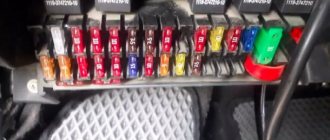
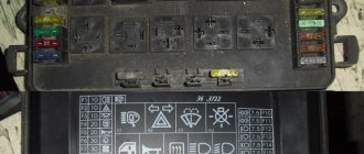
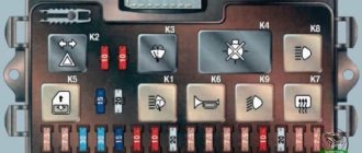
Relays and fuses VAZ 2114
F1 for 10 Amps (A) rear fog lights and rear fog light warning lamp. F2 for 10 A turn signal lamps, turn signal relay, hazard lights, hazard warning lights. F3 7.5 A lamps for interior lighting (both) and trunk, ignition lighting, powertrain control system control lamp, brake lamps, computer, if available. F4 20 A carrier, relay and rear window heating element. F5 20 A horn and its relay, cooling fan. F6 30 A power windows and their relays F7 30 A motor heater, headlight cleaner, windshield washer, cigarette lighter, glove compartment light bulb, rear window heating relay winding. F8 7.5 A right fog lamp. F9 7.5 A left fog lamp. F10 at 7.5 A left side marker, lamp signaling the inclusion of the side light, lamps for illuminating the sign, engine compartment, illumination of switches and instruments, instrument lighting switch. F11 at 7.5 A right side. F12 at 7.5 A right low beam. F13 at 7.5 A left low beam. F14 for 7.5 A left high beam and a light indicating that the high beam headlights are on. F15 at 7.5 A right far. F16 30 A - a light indicating insufficient oil pressure, brake fluid level, engagement of the parking brake, low battery, instrument cluster, relay for monitoring the health of lamps, indication of control systems, reversing lamps, turn indicators and their relays, as well as an alarm if turning mode is turned on, computer, generator excitation winding is turned on at the moment the engine starts.
How to insulate yourself
Motorists insulate the car hood with their own hands.
Independent arrangement includes the following stages of work:
Preparation. First, you will need to dismantle the standard hood sound insulation (if available). The operation should be carried out carefully, trying not to damage it. Afterwards, the working surface is thoroughly washed and degreased. Creating templates. You need to make a pattern for the insulation. For these purposes, use old wallpaper or newspapers. It is necessary to carefully cut out the templates, according to which the insulation elements for the hood will subsequently be cut out. The remaining thermal insulation is cut into small strips, which will subsequently be attached to the stiffeners of the body element. Installation of insulation. When performing this operation, you need to stock up on a small roller, glue and insulation. If work is carried out in an insufficiently heated room, use a hair dryer. The adhesive is evenly applied to the degreased working surface, then the insulation is carefully applied from the corner and gradually fixed to the hood (if you stick the element right away, folds and air bubbles may appear). Afterwards, carefully roll over the glued insulation.
Care must be taken as bulges and dents may appear on the outside of the hood due to excessive pressure on the inside of the body element.
When the cold weather ends, the thermal insulation is dismantled. Before new use, the insulation is repaired and reinstalled on the car.
To quickly warm up the car in low temperatures, you need to use thermal insulation of the vehicle's engine compartment. First of all, the warm-up time is reduced, and as a result, fuel consumption is reduced
The engine cools down more slowly, which is important for motorists who use their cars intensively with short stops. For maximum efficiency, not only the hood, but also the air ducts along with the radiator grille are insulated