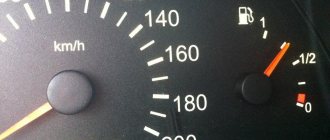
The fuel level sensor on any car, including a VAZ 2114 with an injector engine, is designed to monitor the volume of gasoline in the tank. Using it, the driver can figure out how much fuel is left and when to refuel the car. In this article we will talk about the device, malfunctions, and how to replace the device yourself.
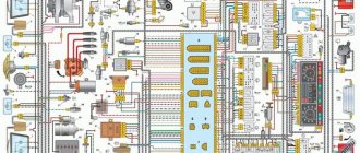
Electrical diagram
- Headlights;
- Geared motors for headlight cleaners;
- Fog lights;
- Ambient temperature sensor;
- Sound signals;
- Engine compartment lamp switch;
- Engine cooling fan electric motor;
- Generator;
- Low oil level indicator sensor;
- Washer fluid level sensor;
- Front brake pad wear sensors;
- Wire ends connected to the common windshield washer pump*;
- Windshield washer pump;
- Headlight washer pump;
- Wire lugs for connecting to the rear window washer pump on VAZ-2113 and VAZ-2114 cars;
- Low oil pressure indicator sensor;
- Engine compartment lamp;
- VAZ-2111 engine:
Wire lug for connection to the wiring harness of the engine control system
VAZ-21083 engine:
Electric fan switching sensor; - Windshield wiper gear motor;
- Starter;
- VAZ-21083 engine:
Block connected to the ignition system wiring harness; - Coolant temperature indicator sensor;
- Reversing light switch;
- Insufficient brake fluid level indicator sensor;
- Accumulator battery;
- Insufficient coolant level indicator sensor;
- Relay for turning on fog lights;
- Mounting block;
- Brake light switch;
- Portable lamp socket;
- Illumination lamp for the headlight hydrocorrector scale;
- Parking brake warning lamp switch;
- Block for connecting a backlight lamp;
- Instrument cluster lamp switch;
- Understeering's shifter;
- Hazard switch;
- Front seat heating element relay;
- Ignition switch;
- Rear fog light circuit fuse;
- Front seat heating elements circuit fuse;
- Door lock circuit fuse;
- Front ashtray illumination lamp;
- Ignition relay;
- Cigarette lighter;
- Glove compartment lamp;
- Glove compartment lamp switch;
- Heater fan motor;
- Additional resistor for heater fan motor;
- Heater fan switch;
- Heater fan switch illumination lamp;
- Heater lever illumination lamp;
- Gear motors for power windows of front doors;
- Right front door power window switch (located in the right door);
- Gear motors for locking front door locks;
- Wires for connecting to the right front speaker;
- Rear door locking motors;
- Wires for connecting to the right rear speaker;
- Door lock control unit;
- Wires for connection to radio equipment;
- Headlight wiper switch;
- Rear window heating element switch;
- Relay for turning on rear fog lights;
- Block for connection to the heating element of the right front seat;
- Rear fog light switch;
- Right front seat heating element switch;
- Fog light switch;
- Outdoor lighting switch;
- Left front seat heating element switch;
- Block for connection to the heating element of the left front seat;
- Wires for connecting to the left front speaker;
- Left front door power window switch (located in the left door);
- Right front door power window switch (located in the left door);
- Wires for connecting to the left rear speaker;
- Side direction indicators;
- Lamp switches on the front door pillars;
- Light switches on the rear door pillars;
- Central interior lamp;
- Front interior lamp;
- Block for connecting to the wiring harness of the electric fuel pump;
- Trunk light switch;
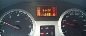
- Instrument cluster;
- Trunk light;
- On-board control system signaling unit;
- Trip computer;
- VAZ-2111 engine:
Block for connecting the wiring harness of the engine control system; - Rear exterior lights;
- Rear interior lights;
- Pads for connecting to the rear window heating element;
- License plate lights;
- Additional brake signal located in the spoiler.
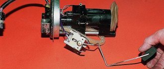
Self-repair of the fuel level sensor
Even an ordinary motorist can repair the FLS in a VAZ 2114. Spare parts for the sensor are sold at an auto supply store. You need to remove the device from the tank and familiarize yourself with its parameters. The marking is located on the front of the plate, directly above the rheostat scale.
If there is a hole in the float, then it will be easy to fix the problem. Pull the float out of the retainer socket and install a new one. If the rheostat scale strips are dirty, they need to be cleaned. The plate must be cleaned with a soft cloth or cotton wool soaked in alcohol. If the wires come off, they can be carefully put back in place by soldering. A cracked plate needs to be replaced with another one.
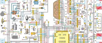
Engine control circuit for VAZ 2111 (January 5.1, Bosch M1.5.4N)
- Fragment of the mounting block;
- Electric engine cooling fan;
- Automotive anti-theft system status indicator;
- Automotive anti-theft system control unit;
- Coolant temperature sensor;
- Air flow sensor;
- Throttle pipe;
- Block connected to the throttle position sensor;
- Block attached to the idle speed control;
- Controller;
- A block connected to the air conditioner wiring harness;
- Oxygen sensor;
- Knock sensor;
- Crankshaft position sensor;
- Speed sensor;
- Adsorber;
- Accumulator battery;
- Main relay;
- A block connected to the anti-lock brake system wiring harness;
- Diagnostic block;
- Main relay circuit protection fuse;
- Controller protection fuse;
- Fuse for protecting the electric fuel pump and its relay;
- Relay for turning on the electric fuel pump;
- Electric fan switch relay;
- A block connected to the instrument panel wiring harness;
- A block connected to the instrument panel wiring harness;
- Ignition module;
- Electric fuel pump with fuel level sensor;
- Spark plug;
- Injectors;
- F — Front harness wire going to the “B+” terminal of the generator; G - Front wiring harness wires.
The order of conditional numbering of plugs in blocks:
- A - Controller; B — Control unit of the automobile anti-theft system; B — Indicator of the status of the automobile anti-theft system; G - Pads 26; D - Throttle pipe; E - Air flow sensor; F - Electric fuel pump and oxygen sensor; 3 — Speed sensor; And - Ignition module.
Purpose of plugs in block 26:
- To the low-voltage tachometer input in the instrument cluster;
- —
- To the engine management system control lamp in the instrument cluster (from the controller);
- To the dome light switch located on the driver's door pillar;
- To the engine control system control lamp in the instrument cluster (+ power supply);
- To the trip computer (fuel consumption signal);
- To the instrument cluster (vehicle speed signal);
- To terminal “15” of the ignition switch (plug 4 of the switch block)
Replacement allowance
If you notice that the regulator no longer works, you will need to replace it. This procedure can be done at home.
Tools and materials
Before you begin the process, prepare:
- new regulator;
- Screwdriver Set;
- a set of keys.
1. New FLS 2. Screwdrivers 1. Set of keys
Stages
So, the replacement procedure is performed as follows:
- Since the controller is part of the fuel pump structure, it will not be possible to dismantle it without touching the module as a whole. To gain access to this structure, it is necessary to dismantle the lower part of the rear seat, and then remove the luggage compartment upholstery.
- Using a 7mm wrench, you need to unscrew the screws on the right and left sides, in particular, we are talking about the gas tank cap latches. These screws also secure the upholstery to the sides.
- Having done this, you will see 8 more screws that secure the edge of the cover; they also need to be unscrewed.
- The next step is to remove the entire fuel tank cap, this can be done by moving it forward a little.
- After these steps, you will see the upper part of the pump; you need to dismantle the wire block that is connected to the device; for this you may need a 17-mm wrench. You will also need to unscrew the nut of the fuel supply line from the fitting. In this case, there is no need to rush, it is better to wait a little, but do everything carefully and correctly. Before completely unscrewing the cap, make one small turn - this will allow you to get rid of the pressure that has built up in the system.
- Next, along the diameter of the cover you can see 8 more small nuts, you need to unscrew them, for this you use a wrench, but it will be more convenient to do this with a ratchet.
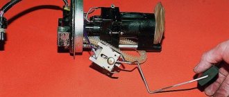
- When dismantling the fuel pump, it should be lifted up, then turned slightly clockwise, and then tilted. Such actions will prevent damage to the device's float.
- After dismantling the module, we begin to disassemble it. Using a slotted screwdriver, you need to move the locking ring located directly on the module. After this, you can remove the cover itself from the structure. You need to remove the wire from the pressure sensor terminal, after which the fasteners are pressed directly from the cover and the blocks with wiring from the fuel pump are disconnected.
- The controller latches are detached, after which the device itself slides along the grooves of the case. The regulator is dismantled and replaced with a new one.
1. Unscrew the nuts on the cover.
2. Slide the adjuster along the grooves. Sorry, there are no surveys available at this time.
Engine control diagram for VAZ 2111 - Euro-2 (Bosch MP7.0)
- Fragment of the mounting block;
- Electric engine cooling fan;
- Automotive anti-theft system status indicator;
- Automotive anti-theft system control unit;
- Coolant temperature sensor;
- Air flow sensor;
- Throttle pipe;
- Block connected to the throttle position sensor;
- Block attached to the idle speed control;
- Controller;
- A block connected to the air conditioner wiring harness;
- Oxygen sensor;
- Knock sensor;
- Crankshaft position sensor;
- Speed sensor;
- Adsorber;
- Accumulator battery;
- Main relay;
- A block connected to the anti-lock brake system wiring harness;
- Diagnostic block;
- Main relay circuit protection fuse;
- Controller protection fuse;
- Fuse for protecting the electric fuel pump and its relay;
- Relay for turning on the electric fuel pump;
- Electric fan switch relay;
- A block connected to the instrument panel wiring harness;
- A block connected to the instrument panel wiring harness;
- Ignition module;
- Electric fuel pump with fuel level sensor;
- Spark plug;
- Injectors.
- F — Front harness wire going to the “B+” terminal of the generator; G - Front wiring harness wires.
The order of conditional numbering of plugs in blocks:
- A - Controller; B — Control unit of the automobile anti-theft system; B — Indicator of the status of the automobile anti-theft system; G - Pads 26; D - Throttle pipe; E - Air flow sensor; F - Electric fuel pump and oxygen sensor; 3 — Speed sensor; And - Ignition module.
Purpose of plugs in block 26:
- To the low-voltage tachometer input in the instrument cluster;
- —
- To the engine management system control lamp in the instrument cluster (from the controller);
- To the dome light switch located on the driver's door pillar;
- To the engine control system control lamp in the instrument cluster (+ power supply);
- To the trip computer (fuel consumption signal);
- To the instrument cluster (vehicle speed signal);
- To terminal “15” of the ignition switch (plug 4 of the switch block)
Electrical diagram for connecting the VAZ 2114 generator model 94.3701
Generator 94.3701 is a synchronous AC electrical machine with electromagnetic excitation with a built-in rectifier based on silicon diodes and an electronic voltage regulator
| Position number on the diagram | Explanation of the position on the diagram |
| 1 | battery |
| 2 | generator VAZ 2114 model 94.3701 |
| 3 | fuse box |
| 4 | battery charge indicator lamp located in the instrument cluster |
| 5 | egnition lock |
The current to excite the generator when the ignition is connected is supplied to terminal “D+” of the regulator (terminal “D” of the generator) through signal light 4 installed in the instrument cluster. After starting the motor, the excitation winding is powered by three additional diodes mounted on the generator rectifier block. The operation of the generator is monitored by a warning light on the dashboard. When the ignition is connected, the light should be on, and after starting the engine, it should go out when the generator is working. A bright glow of the light bulb or its burning at half intensity indicates a malfunction of the generator.
Scheme for testing generator 94.3701 on a stand
| Position number on the diagram | Explanation of the position on the diagram |
| 1 | control 12V, 3W |
| 2 | magneto |
| 3 | voltmeter |
| 4 | rheostat |
| 5 | ammeter |
| 6 | switch |
| 7 | source of electricity |
After running the generator on the stand for 10 minutes, with the rotor rotating at a speed of 6000 rpm, the output current of a working generator brand 94.3701 should be at least 80 A.
Diagram for testing additional generator diodes 94.3701
The short circuit of the additional diodes of the generator 94.3701 can be checked on the car, without removing the generator from it, according to the diagram below. In this case, you need to disconnect the wires from the battery and generator, remove the protective casing of the generator and disconnect the wire from the “D+” contact of the voltage regulator.
If the light is on, then there is a short circuit in one of the additional diodes. A break in additional diodes can be determined by the low voltage at contact “D” at an average rotation speed of the generator armature.
Generator rectifier valve test diagram 94.3701
A working valve allows electricity to flow only in one direction, but a broken valve does not allow electricity to pass through (open circuit), or allows current to flow in both directions (short circuit).
When the light is on, when checking according to diagram “I”, the “negative” and “positive” valves have a short circuit. When checking the valves according to scheme “II”, the light on the lamp indicates a short circuit of one or more positive valves. The glow of the light bulb, when checking the valves according to scheme “III”, means a short circuit in 1 or several “negative” valves. You should be aware that in this case the glow of the light bulb may also be a consequence of the short circuit of the stator winding turns to the generator housing. However, such a breakdown is much less common than valve short circuits.
| Position number on the diagram | Explanation of the position on the diagram |
| 1 | source of electricity |
| 2 | control |
| 3 | magneto |
| I | control of “plus” and “minus” valves at once |
| II | control of positive valves |
| III | control of negative valves |
Heater diagram, rear window heating
- Mounting block;
- Ignition switch;
- Ignition relay;
- Heater motor switch;
- Additional resistor;
- Heater motor;
- Rear window heating switch with turn-on indicator lamp;
- Rear window heating element; K7 - Relay for turning on the heated rear window
Checking the device with an ohmmeter
It is not always necessary to immediately replace the sensor with a new one. It happens that the problem lies in a completely different component of the car, for example, an injector. Also, if the meter is faulty, it may be possible to repair it. Before replacing, check the sensor:
- To test the device, connect a resistance meter to its terminals. This indicator must be measured when the lever and float are in extreme positions or in the middle.
- In the lower position, meaning zero fuel level, the resistance should be 285–385 Ohms.
- In the central position, which means the tank is half full, the ohmmeter should show 100-135 ohms.
- The highest position is a 100 percent filled tank. The ohmmeter should read 7–25 ohms.
If in at least one position the readings obtained diverge from normal, repair or replace the sensor. After installing the new meter, make sure that the installation arrow on the module cover is directed towards the trunk. Otherwise, you will need to dismantle the system again and repeat the replacement.
Diagram of low beam, high beam, rear fog lamps
- Headlights;
- Mounting block;
- Headlight switch;
- Ignition switch;
- External lighting switch (fragment);
- Fog lamps in the interior rear lights;
- Fog light switch with turn-on indicator lamp;
- Headlight high beam indicator lamp in the instrument cluster; K8 - High beam headlight relay; K9 - Relay for low beam headlights; A - The order of conditional numbering of plugs in the headlight block; B - to power supplies
Symptom Definitions
To find the reason that led to the failure of the VAZ 2114 brake lights, you need to have an almost standard set of motorists. Using the tools listed below, you can easily determine the cause of your car's brake lights not working.
Required tool:
- Multimeter;
- Screwdriver;
- Sandpaper (sandpaper);
- A set of keys;
After preparing the necessary tool, you can begin troubleshooting.
Troubleshooting
There can be a huge number of reasons for failure, but as a rule, there are problems of the same type that occur quite often and carry standard solutions.
Main reasons:
- Blown fuse link;
- Breakdown of the brake pedal sensor (frog);
- Brake light bulb filament burnt out;
- Oxidation of the contact on the lamp socket;
- Oxidation of the connector of the entire flashlight;
- Damage to the flashlight board;
- Broken wire;
All of the above reasons are, to one degree or another, the same type and the most common.
Diagram of side lights, brake lights, interior lighting
- Side light bulbs in headlights;
- Engine compartment lamp;
- Mounting block;
- Engine compartment lamp switch;
- Ignition switch;
- External lighting switch (fragment);
- External lighting indicator lamp in the instrument cluster;
- Lamps for side lights and brake lights in the outer rear lights;
- License plate lights;
- Instrument lighting regulator;
- Brake light switch;
- On-board control system unit; K4 - Relay for monitoring the health of lamps (contact jumpers are shown inside the relay, which must be installed in the absence of a relay); A - to power supplies; B - to the backlight lamps of switches and devices; C - to additional brake signal
Common causes of malfunctions
All that remains is to talk about why such situations arise and what the motorist himself needs to do in order to restore the functionality of the horn.
Since a car signal consists of a fairly large number of components, the reasons must be looked for in them. To do this, it is good to understand the device, design and principle of operation of the warning system.
- Blown fuse. A trivial but common problem. The fuse is located in a special block. Look for information in the instruction manual. Sometimes simply replacing the fuse is enough;
- Burnt out relay. Since the horn is powered through a fuse and a relay, the latter is also necessarily checked in the mounting block, and changed if the problem is with it;
- Broken horn. If everything is fine with the relay and fuse, the problem may be in the device itself. To check, you can take the element and directly supply power through the battery. When the horn is working, the signal appears;
- Short circuit. The place to start your search is with the safety socket. And then move along the chain;
- The contact ring on the steering wheel is worn out. It will need to be replaced if necessary;
- The clamping contacts on the column are worn out. A characteristic feature of domestic cars;
- The contacts have oxidized. Check the contact group for rust or signs of oxidation;
- The winding on the horn has burned out. The problem is solved by replacement;
- Violation of electrical contact;
- The cable on the steering wheel where there is an airbag is broken.
Diagram of direction indicators and hazard warning lights
- Turn signal lamps;
- Mounting block;
- Ignition switch;
- Hazard switch;
- Side turn signal lamps;
- Turn signal lamps in the outer rear lights;
- Turn signal lamps in the instrument cluster;
- Turn signal switch; K2 - Relay interrupter for direction indicators and hazard warning lights; A - to power supplies
Problems with the sound signal device
The signaling device mechanism is not protected from moisture getting inside. Why contacts and membrane oxidize. If the external contacts of the wire connecting to the signaling device are oxidized, there is no need to remove it. It is enough to remove the connector and clean the contacts. If this procedure does not help, you will have to remove the alarm device by unscrewing the screws to check the condition of the membrane. Sometimes it is enough to wash the membrane with kerosene or clean it with fine sandpaper. But if a crack or other defect is found on the membrane, then you will have to buy a new signaling device and install it.
Please note that to eliminate the oxidation process inside the signal mechanism, universal lubricant VD-40 helps.
The strength and timbre of the sound of the signaling device is regulated by rotating the adjusting screw on the front wall of its body.
Front wiper and washer diagram
- Windshield washer motor;
- Windshield wiper motor;
- Mounting block;
- Ignition switch;
- Ignition relay;
- Windshield wiper and washer switch; Short circuit - Windshield wiper relay; A - to power supplies; B - Order of conventional numbering of plugs in the block of the wiper motor
Important diagrams of the main electrical devices and systems of the VAZ 2114
Ignition switch terminal connection diagram
| Position number on the diagram | Explanation of the position on the diagram |
| 1 | terminal group of the ignition switch (lock) (0 - “off”: I - “on”; II - “starter”) |
| 2 | light bulb |
| 3 | small switch |
| 4 | wire harness block |
Mounting block connection diagram
The outer number in the designation of the wire tip is the number of the block, the inner number is the conventional number of the tip.
K1 - Relay for turning on headlight cleaners; K2 - Relay interrupter for direction indicators and hazard warning lights; Short circuit - Windshield wiper relay; K4 - Relay for monitoring the health of lamps; K5 - Relay for turning on power windows (in a variant version of the car); K6 - Relay for turning on sound signals; K7 - Relay for turning on the heated rear window; K8 - Headlight high beam relay; K9 - Relay for low beam headlights; F1-F16 - Fuses
Electrical circuit diagrams for VAZ 21140, 21144, 211440, 2113, 2115 cars with a 1.5L (VAZ-2111 and VAZ 21114) and 1.6L (VAZ-11183) injection engine, as well as a 1.5L carburetor engine - VAZ-21083 (Samara 2; 199 7 -2013)
Source
Step-by-step instructions for replacing and repairing the sound signal of a VAZ 2106
- You can adjust the signal without dismantling it. This is done as follows:
- The sound elements are adjusted one by one. This turns off the power from the element that is not currently being regulated.
- The second GE is regulated in the same way, having first turned off the first one.+
- When replacing a faulty electrical element, the power wires are disconnected from it and the nut securing it to the bracket is unscrewed.
- The new sound signal is installed in the reverse order.