Removal and replacement of ECUs on VAZ 2110, 2111 and 2112 vehicles
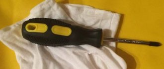
So, the first thing you need to do is disconnect the negative terminal from the battery. Now it's worth noting that to do this simple job you will need the following tool:
- Socket head for 10
- Ratchet handle
- Phillips blade screwdriver
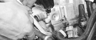
When you get to the engine control unit, you need to disconnect the plug with the wiring harness from it, after opening the metal latch:
Now you need to unscrew the two nuts securing the “brains”, as shown in the photo below:
When these two nuts are unscrewed, you need to slightly move the bar to the right to release it from its engagement:
After which you can carefully remove the ECU:
It is worth noting that if the controller fails, a new one must be installed the same as it was before - from the factory. The price of new controllers can range from 4,500 to 10,000 rubles, depending on the type and year of manufacture of the car. Installation is carried out in reverse order.
Types of ECU (esud, controller). What kind of ECUs are installed on VAZ?
"January-4", "GM-09"
The very first controllers on SAMARA were January-4, GM - 09. They were installed on the first models before the year 2000. These models were produced both with and without a resonant knock sensor.
The table contains two columns: 1st column – ECU number, second column – brand of “brains”, firmware version, toxicity standard, distinctive features.
| 2111-1411020-22 | January-4, without DC, RSO (resistor), 1st ser. version |
| 2111-1411020-22 | January-4, without recreation center, RSO, 2nd ser. version |
| 2111-1411020-22 | January-4, without recreation center, RSO, 3rd ser. version |
| 2111-1411020-22 | January-4, without recreation center, RSO, 4th ser. version |
| 2111-1411020-20 | GM,GM EFI-4,2111,with DC,USA-83 |
| 2111-1411020-21 | GM, GM EFI-4, 2111, with DC, EURO-2 |
| 2111-1411020-10 | GM,GM EFI-4 2111,with DC |
| 2111-1411020-20 h | GM, RSO |
VAZ 2113-2115 from 2003 are equipped with the following types of ECUs:
"January 5.1.x"
The following types of hardware implementation are distinguished:
Interchangeable with “VS (Itelma) 5.1”, “Bosch M1.5.4”
| 2111-1411020-71 | January-5.1.1, without dk, with |
| 2111-1411020-71 | January-5.1.1, without dk, with |
| 2111-1411020-71 | January-5.1.1, without dk, with |
| 2111-1411020-71 | January-5.1.1, without dk, with |
| 2111-1411020-71 | January-5.1.1, without dk, with |
| 2111-1411020-72 | Itelma, without dk, with |
| 2111-1411020-72 | Itelma, without dk, with |
| 2111-1411020-72 | Itelma, without dk, with |
| 2111-1411020-72 | Itelma, without dk, with |
Types of ECU VAZ 2110
The first Russian car with an injection engine is considered to be the VAZ 2110. The operation of the injection engine is controlled by an electronic control unit (ECU), which is the brain in the electronic engine control systems (ECM). In common parlance, ECUs are called “brains”. So what are our VAZs thinking?
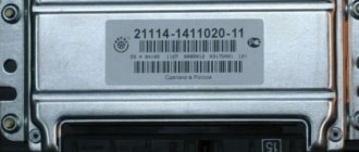
How to determine the ECU on a VAZ? To do this, remove the lower panel panel near the passenger's left foot and read the data on the block.
For the first time, ECMs developed by General Motors (GM) appeared on Russian cars. They were of two types:
- central (for VAZ 21214 and VAZ 21073, 21044).
- distributed fuel injection (front-wheel drive VAZ).
The second serial family of ECMs were the “January-4” systems, which were developed as a functional analogue of GM (with the ability to use the same composition of sensors and actuators) and were intended to replace them. Therefore, the dimensions, fastenings, as well as the pinout of the connectors were preserved.
Development, together with Bosch, of an ECM based on the Motronic M1.5.4 system, which could be produced in Russia. Other air flow sensors (MAF) and resonant detonation sensors (developed and produced by Bosch) were used. The software and calibrations for these controllers were first fully developed at AvtoVAZ. For Euro-2 toxicity standards, new modifications of block M1.5.4 (has an unofficial index “N” to create an artificial difference) 2111-1411020-60 and 2112-1411020-40 appear, meeting these standards and incorporating an oxygen sensor, catalytic neutralizer and adsorber.
In parallel with the M1.5.4 system, AvtoVAZ, together with ELKAR, designed a functional analogue of the M1.5.4 block, which was called January-5.” Initially, versions were released for Euro-2 standards (2112-1411020-41) containing an oxygen sensor, catalytic converter and adsorber. Later, mass production and installation of systems based on control units began:
- "January-5.1.2" for 16 (2112-1411020-71).
- "January-5.1.1" for 8 (2111-1411020-71) valve engines.
In December 2005, NPP Avtel released for spare parts (this was never supplied to the VAZ assembly line.) ECU “January 5.1.x” with modified hardware.
The next step in the fight for environmental friendliness of exhaust was the development, commissioned by AvtoVAZ OJSC, of a more modern unit that could meet more stringent toxicity and diagnostic standards Euro-2 and Euro-3, called MP7.0. In this modification, both the hardware and software were developed, the final calibration and fine-tuning of the systems was carried out by AvtoVAZ OJSC.
NPO Itelma has developed an ECU for use in VAZ cars, called VS 5.1. This is a fully functional analogue of the ECM January 5.1, that is, it uses the same harness, sensors and actuators. Modifications 2112-1411020-42 and 2111-1411020-62 are designed for Euro-2 standards and include an oxygen sensor, catalytic converter and adsorber; this family does not provide for P-83 standards for 2112 engines.
It was produced under Euro-2 and Euro-3 toxicity standards. Installed on cars since September 2003. The ECU is structurally similar to the “canned” modification of Bosch M1.5.4, but smaller in size, with a different connector, 81-pin block. The software of these ECUs is based on Bosch's Torque-Based engine model and contains more than a thousand calibrations. Although the error mask and equipment are present, due to the complexity of the system algorithms, it is not yet supported by calibration editing programs, which imposes some difficulties on chip tuning.
The engine with ECM 2111-1411020-80 is equipped with a new mass air flow sensor (116), a new DF, control of ignition coils built into the ECU (part of the MZ functions) using external Bosch ignition coils; injectors - thin, black, Bosch; there is no “return”, the RTD is located in the tank, assembled with the fuel pump glass. (this applies to 1.6 engines. For 1.5, a “hybrid” was assembled - with a conventional BN and a new type of injector ramp with an RTD).
Controllers with software for 16 cells. engines under Euro-3 standards support the function of software switching of starting calibrations Europe/Russia from diagnostic equipment. This function, according to the developers, should make starting on low-quality gasoline easier. Default to .
The new ECU didn't take long to arrive. As always, “without declaring war,” VAZ released an ECM with a Bosch M7.9.7 of a different modification onto the assembly line. It contains another processor (Thompson) and the software is firmware inside the processor, that is, flash - there is no memory in them, and another eeprom is also used. The firmware of the “old” implementation is not suitable for the “new” one and vice versa. No compatibility. Updated software has already been released for the “new” type of controllers (as of January 2006). The EQ series has been replaced on the conveyor by ER. What is the reason for this, what changes and improvements have been made, as is customary at VAZ, is not reported.
This area has been actively developing and expanding. Versions of the “classic” appeared - B120ES01, however, “made” from 2111 blocks.
ECUs are manufactured in different places, the country of manufacture is indicated on the nameplate. Until some time there were two of them - Germany and Russia, a little later the “French” ones appeared, and subsequently in 2007, ECUs originally from the Middle Kingdom, made in China, began to appear.
Video “No spark and blown fuse - repairing the ECU”
What to do if there is no spark and the fuses are constantly blowing - the video below shows the process of repairing the control controller in a garage (the author of the video is the Auto Practice channel).
I came across an article by McSystem. Actually, here it is below
In January - about Januarys. Again and in detail about the ECM-ECU masses
One of the rather serious problems affecting the stable operation of engines controlled by the January ECU (7.2, 7.2+, M73, 7.9.7) is the “mass problem” of the ECM. Moreover, the point is not so much in bad (or uncrimped) contacts and their fastenings, but rather in the rather incorrect wiring of the ECM harness itself. And the solution is not in “pulling a fancy cable (KG-25 or 50)” to the ECU. Therefore, this material will be devoted to a technically competent approach to solving this problem. What is described below is a kind of compilation, or an attempt to “chew” what has been published more than once, in particular on ChipTuner.ru, and to convey to readers the specifics of solving this problem. The articles by I.N. turned out to be the most complete and informative. Skrydlova, (aka Aktuator) “About the masses”, “MASS: AN UNEXHAUSTABLE SOURCE OF GLITCHES” “ONCE AGAIN ABOUT THE MASSES” ©Oleg Bratkov. Many years ago, having read and comprehended what was written, I implemented it on my typewriter. I completely agree with the conclusion of the author (aka Aktuator): “All the assurances of AVTOVAZ OJSC about improving the quality of electrical connections in manufactured vehicles are not worth a penny. In most cases, it is possible to achieve normal operation of the engine under the control of the ECM I 7.9.7 and January 7.2 only by carrying out additional, and not accepted by the manufacturer as a warranty, work to change the electrical circuit of the car.”
So, on to the topic! Classic ECM 21124 with ECU January 7.2(+) or M7.9.7 Electrical connection diagram of ECM EURO-2 M7.9.7, January 7.2 LADA 2110 with engine 21124. 21124-1411020-30, 21124-1411020-31.32
Fig. 1 ECM 21124 January 7.2, M7.9.7 Noticed, often described and characteristic problems - unstable idle speed, freezing speed, “jerking” of the engine at start and operation of the cooling fan, unreasonable jumps in the electrical parameters of the ECM during diagnostics. And this is not the entire list. And the whole problem is a rather incorrect wiring of the harness masses, not in relation to the body, but to the ECU. Therefore, in this article you will not see recommendations for tightening the “hoses” of additional mass to the ECU, due to its complete uselessness. This is not a newfangled “razmasovka” or “razminusovka”... Don’t get your hopes up!
The main idea voiced by the authors is that the wiring of the power lines of the ECU and fan and low-current sensor masses is fundamentally incorrect. Rice. 12
Fig.2 Ground connections of the ECM. S6, S7, S8
The sensors must be connected to the ground bus of the ECU board and not have contact with the body! There should be no flow of pulsed and direct currents of the ECU and IM in the sensor mass circuit. And the ECU is securely connected to the body. The rationale is to eliminate the influence of ECU currents (pulse and constant) and fan current on the reliability of sensor readings. Classic approach with data collection and processing systems! But not from AvtoVAZ designers, as usual... Now, in order
Fig. 3 Masses according to AvtoVAZ, or how not to do it
1. The ECU masses are combined into three crimps S6, S7, S8, which are combined with each other and TWO bends are already made from them to the body studs B3, B4. 2. A switched minus fan with a rated current of 12A is connected to S6, and at the peak at start - all 20A! ! ! Which in itself is terrible! 3. All this is connected (screwed) to the ECU bracket, which in turn is very flimsily connected to the body. The engine ECM consists of sensors and actuators (AM). Sensors can be easily divided into analog and discrete. Analogue – mass air flow sensor, air pressure sensor, diesel sensor, DD. The output signal of these sensors is a voltage in a certain small range, usually 0 - 5V. For this group, any (even small) interference has a serious impact on the result. Discrete ones - DC (to some approximation), DF, DS (Speed Sensor) - are less critical to interference, because the output signal has two fixed levels high and low, and intermediate levels are not interesting to the ECU. Actuators - ignition coils, injectors, canister valve, DC heating, IAC, relays and other sources of large pulsed and direct currents along the negative (mass) bus of the ECU. To understand what the developers were up to, let’s look at the diagram in Fig. 3 – this is a fragment of the main ECM diagram in expanded form. It immediately catches your eye - the masses of the most sensitive and responsible sensors, mass air flow sensors and diesel fuel sensors, are wired, although there are separate pins for them, 36 and 35, respectively. For what? Silence in response! S6-S7-S8 are connected by jumpers, which makes the situation even worse.
What VAZs “think”: everything about the ECUs on the VAZ 2110-2112 and their replacement
The ECU is the main control module in any car. Thanks to the control unit, the optimal parameters for the operation of the power unit are determined, so this module must always work exactly like a clock. Where is the VAZ 2110 ECU located, what malfunctions are typical for it and how to change the device if necessary - we will talk about this below.
Description of "brains"
The VAZ 2110 is considered the first vehicle in the domestic automobile industry equipped with an injection engine. The power unit is controlled by an ECU, an electronic device that determines the basic parameters of engine operation in accordance with sensor signals. In fact, the ECU of a VAZ 2110, VAZ 2112 or any other model is the “brains” of the car, the operation of which affects the functionality of the vehicle as a whole.
Control controller in VAZ 2110
In the “Tens”, as well as the VAZ 2112, there are 16 valves and other models equipped with BOSCH 7.9.7 or January 7.2 systems, one M6 screw is installed in the head. From this screw the mass is taken to the ignition coils, and the mass is taken directly to the control model in the cabin. Typically, the mass is a welded stud mounted on the ECM bracket, particularly behind the center console, behind the left screen. In this case, the mass is transferred to the bracket through a pin, which is welded on the engine shield in the middle. It should also be noted that the nut on this stud is not usually tightened.
Control unit location
Now let's consider the location of the VAZ 2110 ECU. This device in the Ten is located under the center console, in its lower part, in particular, under the control panel. In order to gain access to the control module, you must remove the plastic panel on the passenger side, to do this you will have to use a Phillips screwdriver. Once you remove the cover, you will see many different wires, plugs, and safety devices. The controller itself is located behind them, it is screwed to the bar in a horizontal position.
The arrow indicates the location of the ECM module behind the center console
Typical malfunctions: their symptoms and causes
If the electronic engine management system malfunctions, this can lead to problems with the operation of the power unit. Unfortunately, ECU malfunctions in dozens of domestic cars are not uncommon, so the car owner should be aware of the main problems, as well as the reasons for their occurrence.
First, let's look at the symptoms of malfunctions:
- There is no connection with the diagnostic tester. If problems begin to appear in the operation of the engine, the car owner can diagnose the performance of the power unit using a tester or laptop. But if the ECU does not work, then when trying to contact the on-board computer, the car owner will see that there is no connection.
- The ECM does not receive signals about the operation of the injectors, ignition system, fuel pump, valve or idle speed sensor. There may also be no signals from other actuators.
- Another sign is the lack of response to the oxygen sensor, engine temperature controller, throttle position sensor and other controllers.
- Mechanical damage to the device can also be a sign of failure. Cracks may appear on the case as a result of strong mechanical impact; radio elements or conductors could burn out (the author of the video about the repair is Pavel Ksenon).
As for the reasons, malfunctions in the electronic control unit can occur as a result of:
- Unskilled intervention. This reason is one of the most common. If a car owner independently carries out electrical repairs or installs an anti-theft system, or entrusts this work to unqualified craftsmen, errors may be made in the process.
- A common problem is lighting a car battery from a vehicle with the engine running. When lighting the engine, the engines of both cars must be turned off, otherwise there is a risk of brain damage, this is important to remember.
- Another problem that does not occur so often is polarity confusion when connecting a car battery. If you confuse plus with minus, it can not only damage the control unit, but also damage the battery itself, which can lead to expensive repairs.
- The reason may be that the battery terminals are disconnected while the engine is running.
- Also, the control unit may fail as a result of turning on the starter unit with the power bus disconnected.
- The engine control system can be damaged if an electrode accidentally hits the sensor or vehicle wiring during welding work.
- One of the most serious problems is water getting into the ECU. If liquid gets into the device, the board itself may become covered.
- A break in the electrical circuit or a short circuit in the wiring.
- The cause may also be malfunctions in the high-voltage component of the ignition system. For example, a breakdown of the ECU can be caused by a failure of the coil, high-voltage cables, distribution mechanism, etc.
Pinout of contacts on the controller
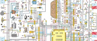
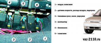
VAZ-2111 engine control system diagram
1 – ignition relay; 2 – battery; 3 – ignition switch; 4 – neutralizer; 5 – oxygen concentration sensor; 6 – nozzle; 7 – fuel rail; 8 – fuel pressure regulator; 9 – idle speed regulator; 10 – air filter; 11 – diagnostic block; 12 – mass air flow sensor; 13 – tachometer; 14 – throttle position sensor; 15 – control lamp “CHECK ENGINE”; 16 – throttle unit; 17 – immobilizer control unit; 18 – ignition module; 19 – coolant temperature sensor; 20 – controller; 21 – spark plug; 22 – knock sensor; 23 – fuel filter; 24 – fan switch relay; 25 – electric fan of the cooling system; 26 – relay for turning on the electric fuel pump; 27 – fuel tank; 28 – electric fuel pump with fuel level indicator sensor; 29 – gasoline vapor separator; 30 – gravity valve; 31 – safety valve; 32 – speed sensor; 33 – crankshaft position sensor; 34 – two-way valve.
Instructions for removing and replacing the computer
The need to dismantle the ECM unit 16 of the ten valve engine arises if repairs are necessary when faults are identified. The repair process itself will depend on what exactly happened in the operation of the ECU. For example, if the contacts on the module connector have oxidized, the unit must be dismantled to clean or replace them. If the reason lies in damage to the housing, then the device must be removed for replacement; if water has gotten inside, then the module should be removed in order to dry it. Only after you have dried the block can it be tested.
If the problem lies in the performance of the board and some burnt-out elements, then you can try to repair it yourself by re-soldering some components. But we would still recommend turning to specialists for help, especially if you have never encountered such a problem before (the author of the video about repairing the control controller is Vyacheslav Chistov).
Where are the brains on the VAZ-2112: ECU on a 16-valve valve
Car : VAZ-2112. Asks : Nikolaev Stepan. The essence of the question : Where is the ECU on the VAZ-2112?
Good afternoon I have a question! Where is the electronic control unit on the VAZ-2112? I heard that it is in an inconvenient place and that it is being reinstalled! And tell me how to change it?
What is an ECU (brains)
The ECU - or electronic control unit on the VAZ-2112 - is the main element that is responsible for the entire cycle of transferring fuel to the engine combustion chamber system , as well as controlling its operation as a whole.
The following two tabs change content below.
- About the expert:
Fan-auto
All my life I have been surrounded by cars! First, in the village, already in the first grade, I was rushing around on a tractor through the fields, then there was JAVA, then a penny. Now I am a third-year student at the Polytechnic Faculty of Automotive Engineering. I work part-time as a car mechanic and help repair cars for all my friends.
Below we will tell you how to find this part in the car and replace it.
Where is the ECU located on the VAZ-2112?
Finding the electronic control unit on the VAZ-2112 will not be difficult, because it is located directly behind the instrument panel, and more specifically in the lower part near the left foot of the front passenger.
It is hidden immediately behind a plastic cover, which is very easy to remove using only a Phillips screwdriver.
After dismantling, we put it aside.
When the protection is removed and a bunch of wires and a block with relays and fuses are revealed in front of you, the ECU controller is located directly above us in a horizontal and tightly fixed state on a special mounting plate.
Tool for work
To ensure that the work on dismantling the ECU does not take much time, prepare all the necessary tools in advance:
- Ratchet key.
- Socket head at "10".
- Crosshead screwdriver.
Step-by-step procedure for removing the ECU
- First of all, we ensure that the car is parked on a flat surface and put the handbrake on.
- Then open the hood of the car and disconnect the negative terminal from the battery.
- Next, we move into the interior and, with careful movements, disconnect the block with the wiring harness from the ECU, having previously unfastened the latch.
The latch is indicated by an arrow.
The nuts are clearly visible after dismantling the wiring harnesses.
What should I change it to?
Please note that if your old controller fails, you should replace it with exactly the same one that was installed previously - that is, straight from the factory. The price of such devices, depending on the type and year of manufacture of your car, can be in a wide range and range from 4,500 to 10,000 rubles .
Hello everyone, I am the proud owner of a VAZ-2112 and I can tell you a lot of interesting things about it. In particular, the ECU is also an electronic control unit, on this car model, and in principle as on basically all VAZ models, it is located in a very inconvenient place, namely under the torpedo trim on the passenger side, in order to get to it, you need to take Phillips screwdriver and go ahead.
Hello. I seem to have figured out where the ECU is located, but my question is, can it be reinstalled in a more convenient place?
The electronic control unit on the VAZ-2112 is located under the torpedo trim on the passenger side. Then all that remains is to take a Phillips screwdriver and get to it.
The site is replete with advertising. It's not pleasant to be on the page.
Where is the VAZ 2110 injector ECU located?
Before performing work, familiarize yourself with the precautions for repairing the engine control system (see 8.4.1).
1. We prepare the car for the work (see 5, paragraph 2).
2. Using a Phillips screwdriver, unscrew the three self-tapping screws securing the right trim of the instrument panel console and remove the trim.
10 mm socket wrench
loosen the two nuts securing the ECU.
4. By moving it forward, we remove the plastic bracket of the ECU from engagement with the studs of the bracket for the electronic units and remove the ECU from under the console.
5. Having released the clamp of the wiring harness block, disconnect the block from the computer.
10 mm socket wrench
Unscrew the four bolts securing the ECU to the bracket.
7. Remove the ECU from the bracket. Installation
We install the electronic unit in the reverse order.
Location of engine control system components
1 – crankshaft position sensor (not visible); 2 – nozzle (not visible); 3 – idle speed regulator; 4 – throttle position sensor; 5 – oxygen sensor (not visible); 6 – fuel pressure regulator in the fuel rail; 7 – speed sensor (not visible); 8 – mass air flow sensor; 9 – coolant temperature sensor; 10 – ignition module; 11 – knock sensor.
The VAZ-2111 engine uses a distributed fuel injection system (each cylinder has a separate injector). The injectors are turned on in pairs (for cylinders 1–4 and 2–3) when the pistons approach top dead center (TDC).
Some engines are equipped with a feedback injection system (oxygen sensor) and a neutralizer in the exhaust system. This system does not require adjustment or maintenance (if exhaust gas toxicity standards are exceeded, failed components are replaced).
On other parts of the engines, the oxygen sensor and converter are not installed. In this case, the toxicity of exhaust gases is regulated by a CO potentiometer using a gas analyzer.
Source
Description
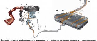
Fuel injection system diagram
1 – air filter; 2 – mass air flow sensor; 3 – inlet pipe hose; 4 – coolant supply hose; 5 – throttle pipe; 6 – idle speed regulator; 7 – throttle position sensor; 8 – channel for heating the idle system; 9 – receiver; 10 – pressure regulator hose; 11 – controller; 12 – relay for turning on the electric fuel pump; 13 – fuel filter; 14 – fuel tank; 15 – electric fuel pump with fuel level sensor; 16 – drain line; 17 – supply line; 18 – pressure regulator; 19 – inlet pipe; 20 – injector ramp; 21 – nozzle; 22 – speed sensor; 23 – oxygen concentration sensor; 24 – gas inlet of the muffler exhaust pipe; 25 – gearbox; 26 – cylinder head; 27 – outlet pipe of the cooling system; 28 – coolant temperature sensor; A – to the supply pipe of the coolant pump
Controller 2110
1 – programmable read-only memory (PROM)
The controller (Fig. Diagram of the fuel injection system) (electronic control unit), located under the instrument panel console, is the control center of the fuel injection system. It continuously processes information from various sensors and controls systems that affect exhaust emissions and vehicle performance.
The controller receives the following information:
- about the position and speed of the crankshaft;
- about engine air mass flow;
- about the coolant temperature;
- about the throttle position;
- about the oxygen content in the exhaust gases (in a feedback system);
- about the presence of detonation in the engine;
- about the voltage in the vehicle’s on-board network;
- about the speed of the car;
- about the position of the camshaft (in a system with sequential distributed fuel injection);
- about a request to turn on the air conditioning (if it is installed on the car).
Based on the information received, the controller controls the following systems and devices:
- fuel supply (injectors and electric fuel pump);
- ignition system;
- idle speed regulator;
- adsorber of the gasoline vapor recovery system (if this system is on the car);
- engine cooling fan;
- air conditioning compressor clutch (if the car has one);
- diagnostic system.
The controller turns on the output circuits (injectors, various relays, etc.) by connecting them to ground through the output transistors of the controller. The only exception is the fuel pump relay circuit. The controller only supplies +12 V to the winding of this relay.
How to independently replace an electronic engine control unit (ECU, ECM, controller)
The electronic engine control system detects failures associated with wire breaks, short circuits to each other or to ground. With poor contact quality in the connectors. And also with a malfunction of the sensors themselves. However, there are malfunctions in the power and ignition systems that have external signs (which are noticed by the driver), but no fault codes are recorded in the memory of the electronic unit.
Main symptoms of malfunctions:
- Difficulty starting the engine.
A normal start is considered to be when the engine starts in one to three attempts. In this case, the starter should be turned on for 10 - 15 seconds, with a break between attempts of one minute. In this case, the minimum crankshaft rotation speed should be 60 - 80 revolutions per minute or one revolution per second.
If, when starting the engine, the battery voltage drops to eight volts (determined by the voltmeter on the instrument panel), then these are poor starting conditions (low ambient temperature) or the battery capacity is less than nominal. Quite often, a voltage drop is associated with oxidation of the battery terminals. Also, starting the engine will be difficult at low temperatures and high oil viscosity.
The following elements of the electronic system may be associated with the appearance of this symptom: mass air flow sensor, throttle position sensor, crankshaft position sensor, coolant temperature sensor, idle speed control, injector tightness, injector clogging, malfunctions in the ignition module (high-voltage wires are pierced , spark plug tips, the spark plugs themselves are faulty, the high-voltage terminals of the ignition coils are heavily oxidized). Lack of required fuel pressure due to a malfunction of the fuel pump or pressure regulator.
— jerks or failures in engine operation.
When you press the gas pedal, there is no expected acceleration. A well-warmed-up engine should, when you sharply press the gas pedal, increase the crankshaft speed from low (800-900 rpm) to high (5000 rpm) in no more than 0.75 seconds.
The following elements of the electronic system may be associated with the appearance of this symptom: mass air flow sensor, oxygen sensor, clogged injectors. This symptom can also appear when the injectors are unbalanced, there is a malfunction in the ignition module (high-voltage wires, spark plug tips are punctured, the spark plugs themselves are faulty, the high-voltage terminals of the ignition coils are heavily oxidized. Lack of the required fuel pressure due to a malfunction of the fuel pump or pressure regulator.
— insufficient throttle response (power).
When the car is moving, downshifts are often used. The speed is picking up slowly. There is a feeling that the engine “does not pull, it’s dull.”
The following elements of the electronic system may be associated with the appearance of this symptom: mass air flow sensor, oxygen sensor, clogged injectors, unbalanced injectors, lack of required fuel pressure due to a malfunction of the fuel pump or pressure regulator. You should check whether the throttle valve opens fully and whether the exhaust system is clogged.
- frequent detonation.
A sharp metallic knock is heard, changing when the throttle valve is opened. The main factors contributing to the occurrence of detonation are temperature and pressure in the combustion chamber. As well as the ignition timing.
The following elements of the electronic system may be associated with the appearance of this symptom: mass air flow sensor, coolant temperature sensor, oxygen sensor, knock sensor, lack of required fuel pressure due to a malfunction of the fuel pump or pressure regulator.
The air filter should be replaced. If the filter is heavily contaminated, the correspondence between the action on the gas pedal and the signal from the mass air flow sensor sent to the control unit is disrupted.
The temperature in the combustion chamber depends on the health of the cooling system. If the engine overheats, you need to check the coolant level, the coolant pump drive belt, the operation of the electric fan of the cooling system, contamination of the radiator, the absence of vapor locks in the cooling system, and the operation of the thermostat.
- delays, twitching, failures.
This is most noticeable when starting off.
When you press the gas pedal, the engine does not immediately respond by increasing the crankshaft speed. Such delays can occur at all vehicle speeds.
The following elements of the electronic system may be associated with the appearance of this symptom: mass air flow sensor, throttle position sensor, injector imbalance, lack of required fuel pressure due to a malfunction of the fuel pump or pressure regulator, malfunctions in the ignition module (high-voltage wires, spark plug tips, etc.) the spark plugs themselves are faulty, the high-voltage terminals of the ignition coils are heavily oxidized).
— interruptions in engine operation.
Uneven engine operation. When the crankshaft rotation speed changes, jerking begins, especially when the load increases. There is a constant popping noise in the muffler at idle.
First you need to check the ignition system (high-voltage wires, spark plug tips, etc.). The resistance of the high-voltage wires of the first and fourth cylinders should be no more than 1 kilo-ohm (1000 ohms), and the resistance of the wires of the third and second cylinders should be no more than 0.9 kilo-ohms (900 ohms). The resistance of spark plug tips is within 7-8 kilo-ohms (7000-8000 ohms). With a higher resistance, the reliability of the ignition system operation decreases; with a lower resistance, electromagnetic interference will occur, affecting the operation of the crankshaft position sensor, as a result of which misfires are possible.
The correct operation of the same sensor can be disrupted by magnetization of the toothed synchronization disk (checked with a thin steel plate).
The following elements of the electronic system may be associated with the appearance of this symptom: imbalance of injectors, lack of required fuel pressure due to a malfunction of the fuel pump or pressure regulator.
- increased fuel consumption.
Tire pressure is below normal, a malfunction of the brake system (braking of one or more wheels), an aggressive driving style, all malfunctions in the engine, power and ignition systems, malfunctions in the cooling system.
The following elements of the electronic system may be associated with the appearance of this symptom: mass air flow sensor, coolant temperature sensor, oxygen sensor, injector seals are broken, lack of required fuel pressure due to a malfunction of the fuel pump or pressure regulator.
— unstable engine operation, stopping at idle.
Air leaks behind the mass air flow sensor, improper operation of the idle air control.
The following elements of the electronic system may be associated with the appearance of this symptom: crankshaft position sensor, coolant temperature sensor, mass air flow sensor, throttle position sensor, injector imbalance, lack of required fuel pressure due to a malfunction of the fuel pump or pressure regulator, faults in ignition module (high-voltage wires and spark plug tips are pierced, the spark plugs themselves are faulty, the high-voltage terminals of the ignition coils are heavily oxidized), the seal of the injectors is broken.
— a strong smell of gasoline in the exhaust system.
This phenomenon usually occurs when the working mixture is very rich, and the enrichment is associated with a misfire. It is also not recommended to idle the engine for long periods of time.
The following elements of the electronic system may be associated with the appearance of this symptom: mass air flow sensor, crankshaft position sensor, coolant temperature sensor (Coolant temperature sensor), oxygen sensor, injector imbalance, lack of required fuel pressure due to a malfunction of the fuel pump or regulator pressure, malfunctions in the ignition module (high-voltage wires, spark plug tips are punctured, the spark plugs themselves are faulty, the high-voltage terminals of the ignition coils are heavily oxidized).
— self-ignition of the fuel mixture.
After turning off the ignition, the engine continues to run unevenly. This type of engine operation is associated with increased temperature in the combustion chamber and the presence of fuel in it. When this symptom appears, you should check the tightness of the injectors.
— popping noises in the muffler or in the intake manifold.
Popping noises in the intake manifold indicate a lean mixture. And the popping noise in the muffler is a rich mixture and its remains ignite in the heated muffler.
The following elements of the electronic system may be associated with the appearance of this symptom: mass air flow sensor, throttle position sensor, injector imbalance, lack of required fuel pressure due to a malfunction of the fuel pump or pressure regulator.
You can purchase an electronic engine control unit (ECU, ECM, controller) from us!
To get to the electronic engine control unit (ECU, ECM, controller), you need to perform the following steps:
— Open the hood.
— Disconnect the wire from the negative terminal of the battery, so that suddenly a short circuit does not occur, which could destroy the ECU.
— Open the front passenger door.
— Unscrew the side fastenings from the console of the car’s instrument panel using a Phillips screwdriver.
— You get direct access to the engine control unit.
— Unscrew the 2 screws holding the controller.
— Take the block with one hand and gently pull it towards the front passenger door. At the same time, hold the wires with your other hand so that they do not rest against the carpet.
— Disconnect the unit from the wires. To do this, look for where the connector lock in the form of a bracket is located and pull it to the side.
— You receive a car without an ECU, ready to install new equipment.
You can purchase an electronic engine control unit (ECU, ECM, controller) from us!
Before installing a new engine control unit on a VAZ, it is worth remembering that not all ECM models are suitable for this.
We recommend installing ECUs from Itelma and Avtel on your VAZ.
Among the advantages of such blocks it is worth highlighting:
- ease of installation;
- low cost;
— compatibility with almost all models of domestic cars, regardless of configuration;
— engine control units from these manufacturers already have standard firmware with the latest updates upon purchase.
Reassemble everything in reverse order and with a new electronic engine management system. Do not forget to connect the connector with wires to the ECU, connect the wire to the negative terminal of the battery. Then you check the work of the controller. Good luck on the roads.