I have seen more than once that people connect the fan directly without a relay or any fuses... And no one thinks about how dangerous this is and how hot the button is! Here is a small manual with weight control which is safer.
A little theory: when mass is applied to contact (85), it closes to (86), the constant “+12v” contact, the winding is triggered and bridges contacts (30) and (87). those. A negative is applied to the fan wire and it works!
Added a complete connection diagram for forced fan activation!
To maintain the engine temperature, the VAZ 2110 cooling fan switching circuit is used. Switching the fan motor on and off is controlled automatically.
Circuit diagram for switching on the cooling fan for a VAZ 2110 carburetor engine.
The circuit diagram for switching on the cooling fan of the VAZ 2110 on carburetor and injection cars is different. On cars with a carburetor engine, a thermobimetallic sensor TM-108 is used for this, and on cars with an injection engine, control is carried out by a controller.
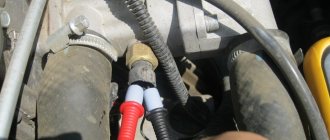
When the fan is controlled by a sensor, the switching temperature depends on the sensor setting temperature, which is indicated on the housing. If the fan does not turn on when the temperature rises to the sensor response temperature, you must first check the serviceability of the sensor. To check, just close the contacts on the sensor and if it turns on, you need to change the sensor. If after closing the terminals the fan does not work, then the cooling fan switching circuit and the integrity of the fuse need to be checked.
Types of cooler plugs and their pinouts
In principle, the purpose of all existing fans is to cool the hardware installed in the system unit. But there are different diagrams for connecting coolers to the power supply and depend on their design. Now there are three main types of these units, differing in the number of pins in the block, and therefore in the circuit and order of connecting the fan.
2 pin
This type of cooler, designed to cool a system unit or power supply, is perhaps the oldest. Now it is practically out of production, but you can still find it in the store. The socket of such an electrical device has two contacts.
The purpose of the wires in such a block is as follows:
- black - minus (general);
- red - +12 V.
Everything is simple here. We supply 12 volts, observing the polarity, the impeller rotates. Speed adjustment, of course, is not provided for in this design.
3 pin
This type of electric fans replaced the two-wire one. An additional wire that appears in the connector allows the computer to measure the rotation speed of the impeller and monitor the health of the cooling system using software.
3 pin connection block
The purpose of the wires in such a block will be as follows:
- black - minus (general);
- red - +12 V;
- yellow - signal from the rotation sensor.
4 pin
The most “advanced” type. Its block is equipped with another additional wire, with which the processor can change the speed of rotation of the impeller at its discretion.
Let's look at the purpose of the wires in this block:
- black - minus (general);
- yellow - +12 V;
- green - signal from the rotation sensor;
- blue—rotation speed control.
Please note that in a four-pin design, the green wire, not the yellow wire, is responsible for the signal from the rotation sensor. And yellow is now responsible for nutrition. Why such modernization was made is unknown. Possibly to confuse the average user and force him to contact a service center, and to force the especially cunning ones to burn their brand new cooler.
The fan does not turn on.
But there are malfunctions in which the controller does not recognize the malfunction and the fan may not turn on when the temperature reaches above 105 degrees. C. In this case, to check the circuit and sensor, it is necessary to remove the connector from the temperature sensor while the engine is running. If the circuit is working properly and the sensor is malfunctioning, the fan will turn on and turn off when the connector is returned to its place.
If the circuit malfunctions, it is necessary to check the integrity of the fuse, the serviceability of the relay and wires, according to the circuit. For a quick check, you need to bridge terminals 30 and 87 of the fan relay, located in the heater shaft on the passenger side. If the fan works, without removing the relay from the block, connect the case and pin 86 of the relay with a test lamp, the relay should work and the fan should turn on. In this case, the controller or the wire connecting the relay to pin 46 of the controller is faulty.
If you do not hear the characteristic click of the relay turning on, and a positive signal is supplied from the main relay to pin 85 of the relay, and if there is a click and the fan does not turn on, change the relay. When installing a jumper between pins 30 and 87 does not turn on the fan, check the integrity of the fuse and the presence of power at the fan terminals. If there is power on one terminal and no power on the other, this indicates a possible malfunction of the fan motor.
Scheme for switching on the cooling fan of an injection engine.
Maintaining normal engine operating temperature is very important to maintain engine performance. The cartoon arrow on the instrument panel, of course, shows the temperature not at all accurately and gives, rather, approximate indicators. The electronic engine control system of the VAZ-2110 with any injection engine uses completely different data, more accurate. They affect the operating temperature and the frequency of turning on the cooling fan.
Connection options
If the number of contacts on the cooler connector and the fan itself matches, then there is no problem. The connectors are connected to each other, non-compliance with polarity is excluded due to the presence of a key . If they do not match, then options are possible.
3-pin to 4-pin
The three- and four-pin connectors are fully compatible with each other , both electrically and mechanically. Structurally, they are designed in such a way that the key allows the connection to be made, and there will be no pinout conflict.
Connecting a 3-pin fan to a 4-pin connector.
If the cooler has a connector with 3 pins, and a harness with 4 pins comes from the computer, then the power wires are connected at the terminal, as well as the speed measurement circuits. The PWM control wire remains unconnected.
Connecting a 4-pin fan to a 3-pin connector.
If the cooler has a connector with 4 pins, and a terminal with 3 pins comes from the computer, then on the electric motor side will remain unconnected In both cases, speed control via PWM is not possible.
Connecting directly to power supply wires
In cases where automatic airflow control is not required (usually case fans), they can be powered directly from the power supply. In this case, the coolers will turn on when the power supply starts, and stop when it turns off. It is rational to make such a connection for fans with two pins (without speed control). There are no fundamental restrictions for using 3- and 4-pin coolers in this capacity, but they are more expensive.
Molex male-female adapter with a branch to the cooler.
The easiest way is to connect a two-pin fan directly to an empty Molex connector. It is more convenient to do this using a Molex male-to-female adapter with a branch for the cooler connector. If there is no free Molex in the harness from the power supply, but there is, for example, an unused SATA power terminal, you can switch from it to Molex, and then to the fan.
The number of detachable connections should be minimized. It’s even better (if you have the skills and qualifications) to cut off the terminals, and then twist the power wires together with the following soldering and insulation of the connection point.
When does the radiator fan turn on on a VAZ-2110
To really understand how to change the fan switching temperature on a VAZ-2110 injector, you need to know exactly the factory design parameters and the principle of fan switching itself.
In carburetor engines, the fan turned on at about 100 degrees.
On old-style 2110 carburetor engines, the fan was turned on using a thermobimetallic sensor. It was installed directly in the radiator bank and set to a certain temperature. Since the normal operating temperature of antifreeze is 80-90 degrees , the bimetallic plate made contacts at approximately 100-105 degrees .
Expansion tank cap
The last reason why the VAZ-2110 cooling fan does not work may be a malfunction of the expansion tank cap. The fact is that when the engine is running, a pressure above atmospheric pressure is created in the cooling system, due to which the water, which is part of the coolant, does not boil at 100 ° C. The expansion tank cap valve is designed to maintain the required pressure. If it fails, the pressure in the system will be equal to atmospheric pressure. This will cause the coolant to begin to boil already at 100 degrees. A sensor designed to turn on at a higher temperature will naturally not work.
It is unlikely that you will be able to check the operation of the cover at home, so if during a visual inspection you have doubts about its functionality, it is better to replace it immediately.
How to change the temperature?
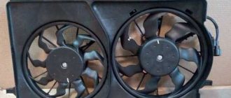
Over time, more and more complaints appear about the operation of the cooling fan activation system. The most important design flaw is the lack of several fan operating modes and the abrupt start of its motor . Indeed, in the summer heat the fan has to work at full strength, and this is understandable. However, most often the fan produces excessive performance, which leads to rapid cooling and frequent starts.
This leads to a current overload on the on-board network.
In addition, the starting temperature threshold is too high, so the engine often overheats . Unfortunately, you can only change the fan startup parameters by reflashing the electronic control unit or upgrading the electric motor activation system. Reflashing the ECU is carried out by a competent specialist, and it is possible to set any desired temperature for turning the fan on and off.
Basic methods
Diagram for connecting an additional fan sensor.
There are also several solutions to changing the operating modes of the fan motor. The simplest of them is to install an additional switching sensor from carburetor engines (in the diagram above). It is configured to turn on at a temperature of 97-100 ° C , which will be quite enough. And in order for the fan to operate in this mode at half power, a resistance from the VAZ heater is installed in the circuit.
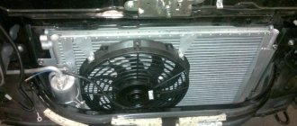
The radiator fan is one of the main elements of the engine cooling system. Its role is to force the radiator to flow when heating the coolant to a certain temperature.
Cooling system design features
Depending on the design features, the fan can be turned on in 3 ways:
- using a power sensor for activation of the VSO. This sensor is also called a fan temperature relay, since the power contacts of the electric motor pass directly through the sensor. With this scheme, the load on the thermal relay increases significantly, which reduces its service life;
- using the fan switch sensor, but now closing the contacts in the temperature switch triggers the relay, through which the power contacts of the cooling fan are connected. This connection method is much more reliable than the previous option;
- using an electronic engine control unit. The ECU, focusing on the coolant temperature sensor installed in the engine cooling radiator, supplies power to the VCO through a relay. A resistive temperature sensor is used as a meter. It is this switching circuit that is used on the vast majority of modern cars. On cars equipped with air conditioning, one of the electric fans will be controlled by the comfort unit. This is necessary for forced cooling of the condenser when the interior air conditioning system is activated.
How does the fan turn on?
Unlike carburetor engines, in VAZ 2110 injection engines the fan is turned on not directly from the temperature sensor, but through the electronic control unit (ECU). The sensor is installed on the outlet pipe of the cylinder head.
VAZ 2110 injector cooling fan does not turn on: reasons, how to check
When the coolant heats up to a temperature of 100-107 0 C, the sensor is triggered and sends a signal to the ECU, which processes it and sends it to the relay. The relay closes the circuit and supplies power to the fan drive (electric motor) through a fuse.
Considering the described switching process, the reasons for the fan not working may be:
- faulty temperature sensor;
- faulty relay;
- blown fuse;
- electrical circuit break;
- Problems with the electric fan drive.
In addition, the expansion tank cap can also affect the timely activation of the fan. If it is faulty and its valve is not capable of maintaining pressure above atmospheric, the water, which is part of the coolant, will definitely boil at 100 0 C, and the sensor set to a higher temperature will not have time to operate.
How to check the thermostat
The function of the thermostat in an internal combustion engine is to regulate the flow of coolant, directing it in either a small or large circle. While the engine is cold, its valve blocks the flow of coolant into the cooling radiator. This allows the engine to warm up faster.
Check the thermostat by determining the temperature of its pipes by touch. When the engine is warm, they should all be hot. If the pipe leading from the thermostat to the cooling radiator is cold, the locking device is faulty.
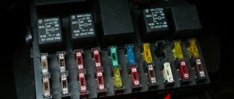
How to check the fan circuit
1. We start the test with the simplest thing - determining the condition of the fuse. We are looking for it in the mounting block, which is located under the hood. Its marking is F7.
2. We take it out, and visually, or using a multimeter, check for functionality. If it burns out, replace it with a new one (20 A). If everything is fine with him, we put him in his place and move on.
Fan connection 2108, 2109, 21099
Until 1998, on cars with the old mounting fuse block 17.3722 (finger type fuses), relay 113.3747 was included in the fan circuit. After 1998 there is no such relay.
Also, before 1998, the TM-108 switching sensor was used (the closing temperature of its contacts is 99±3ºС, the opening temperature is 94±3ºС), after 1998 the TM-108-10 with similar temperature ranges or its analogues from different manufacturers. The TM-108 sensor only works in conjunction with a relay; the TM-108-10, reinforced for high current, can work both with and without a relay.
Scheme for switching on the engine cooling fan on a VAZ 2109 with mounting block 17.3722
- Fan motor
- Motor start sensor
- Mounting block
- Ignition switch
K9 - Relay for turning on the fan motor. A - To terminal “30” of the generator
Scheme for switching on the engine cooling fan on a VAZ 2109 with mounting block 2114-3722010-60
- Fan motor
- Sensor 66.3710 for turning on the electric motor
- Mounting block
A - To terminal “30” of the generator
Video - connecting and checking VO
CLICK HERE AND OPEN COMMENTS
From the relay (from the forced on button) on the spiral from the classic stove, then parallel to the TM-108-10 into the new “female” wires, respectively, the VO turns are 1.5 (through one spiral) and 2 times (through two in series ), as a result, the VO is not audible, does not vibrate and does not break the fan bearings, it is enough in a traffic jam and around the city, it does not go beyond 90g, when slipping, the TM-108-10 will turn on itself (that is, there was 8 volts through the spirals, the TM-108 closed and it became 14, since it is connected in parallel.) Works for 3 years on carb 2110.
Source
Connection diagram for VO VAZ 2110
The circuit diagram for switching on the cooling fan of the VAZ 2110 on carburetor and injection cars is different. On cars with a carburetor engine, a thermobimetallic sensor TM-108 is used for this, and on cars with an injection engine, control is carried out by a controller.
Modifications of the VAZ-2112 car
VAZ-21120 . Modification with a 16-valve injection engine with a volume of 1.5 liters and a power of 93 horsepower. 14-inch wheels were installed on the car. This modification has a problem with valves bending when the timing belt breaks. The problem can be solved by increasing the depth of the grooves in the piston bottoms.
VAZ-21121 . The car was equipped with a VAZ-21114 8-valve injection engine with a volume of 1.6 liters and a power of 81 horsepower.
VAZ-21122 . Budget modification with an 8-valve injection engine VAZ-2111. The car was produced without electric windows, the wheels were 13 inches in size, and the brakes were unventilated from a VAZ-2108 car.
VAZ-21123 Coupe . Three-door, five-seater hatchback. The only two doors for entering the car are 200 millimeters wider than those of the five-door hatchback, and they are mounted on new, durable hinges. The rear arches of the car have become wider. The engine was installed with a 16-valve injection engine with a volume of 1.6 liters and a power of 90 horsepower. The car was produced from 2002 to 2006 in small quantities, the reason for this was the high cost of the car.
If the cooling fan does not work
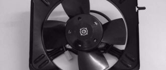
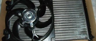
To drive the fan, a DC electric motor with excitation from permanent magnets ME-272 or similar is installed. Technical data of the electric fan and fan switch sensor:
- Rated rotation speed of the electric motor shaft with impeller, 2500 – 2800 rpm.
- Electric motor current consumption, 14 A
- Sensor contact closure temperature, 82±2 degrees.
- Sensor contact opening temperature, 87±2 degrees.
The cooling system fan may not turn on due to:
- electric drive malfunctions;
- blown fuse;
- faulty thermostat;
- a failed thermal sensor for turning on the cooler;
- faulty VO relay;
- broken electrical wiring;
- faulty expansion tank plug.
To check the VAZ fan electric motor itself, we apply 12 V voltage from the battery to its terminals - a working motor will work. If the problem is with the fan, you can try to repair it. The problem is usually the brushes or bearings. But it happens that the electric motor fails due to a short circuit or break in the windings. In such cases, it is better to replace the entire drive.
The BO fuse is located in the mounting block of the car's engine compartment and is designated F7 (20 A). The test is carried out using a car tester turned on in probe mode.
- In a car with a carburetor engine, you need to check the sensor - turn on the ignition and short-circuit the two wires going to the sensor. The fan should turn on. If this does not happen, the problem is definitely not with the sensor.
- For injection cars, it is necessary to warm up the engine to operating temperature and disconnect the sensor connector, disconnecting it from the vehicle’s on-board network. In this case, the controller must start the fan in emergency mode. The electronic unit perceives this as a failure in the cooling system and forces the fan drive to operate in constant mode. If the drive starts, the sensor is faulty.
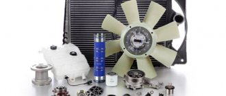
Replacing an electric fan in a car
- We park the car on a flat surface and immobilize it with the parking brake.
- Open the hood and disconnect the negative terminal.
- Using a 10mm wrench, unscrew the fastenings of the air filter housing.
- Using a screwdriver, loosen the air duct clamp on the air flow sensor and remove the corrugation.
- We unscrew the screws securing the cover of the air filter housing and remove the filter element.
- Using a size 8 wrench, unscrew the air intake mount and remove it.
- Using a 10mm wrench, then an 8mm wrench, unscrew the nuts securing the fan casing around the perimeter (6 pieces in total).
- Disconnect the wire block on the fan connector.
- Carefully remove the fan casing along with the drive.
- Using a 10mm wrench, unscrew the 3 bolts holding the electric motor to the casing.
- We put a new one in its place.
- We install the structure in place, fix it, and connect the connector.
- We carry out further installation in the reverse order.
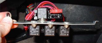
Control circuit modernization
The cooling fan on the top ten turns on at a temperature of 100-105°C, while the normal operating temperature of the engine is 85-90°C, so the fan turns on when the engine overheats, which naturally has a negative effect.
This problem can be solved in two ways: adjust the switch-on temperature in the “brains” or make a button. We'll focus on the second one. Turning on the fan from the button is very convenient: if you get into a traffic jam, turn it on, drive out, turn it off, and no overheating occurs.
A button for selecting the fan operating mode was installed in the cabin (always off, constantly on, automatically turned on via a sensor) - this “tuning” is not mandatory, but will be a very useful addition.
There will be a large current at relay contacts 87, 30, on the wire from the battery to the fuse and the fan ground, and therefore we must use wires there with a cross-section of at least 2 mm, otherwise the thinner wire will not withstand it and will burn out.