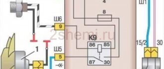
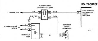
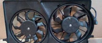
All cars with an injection engine have an electric fan, not a mechanical one. With mechanics, everything was simpler... The fan motor is connected to the network through a relay, and the signal to this relay is supplied by the ECU . Additionally, there is a fuse in the motor circuit, and the antifreeze temperature sensor (ATS) is connected directly to the ECU. If the cooling fan does not work, you can do one trick on the VAZ-2114: turn off the DTOZh sensor and start the engine. And if the fan starts spinning, the problem must be looked for in the sensor.
To avoid having to examine the wiring inside and out, just watch one video. Everything here has already been done.
Cooling fan diagnostics - trying to find the problem
There will be two temperature sensors: one, which is on the thermostat, is connected to the ECU. It is necessary to turn it off - leave the second one as it is.
DTOZH on engine 11183
We disconnect the connector, but do not remove the sensor itself. Then we turn the key to position 1, and so on.
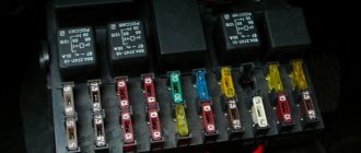
Electrically, things look complicated: the fan relay is in one box, and the fuse is in another. We need fuse F5 (20A). By the way, both a fan and a horn are connected to it.
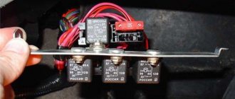
Mounting block 2114-3722010-60 and 2114-3722010-10
The main mounting block is installed under the hood, and the additional one is located at the left foot of the front passenger.
Additional mounting block (option 1)
In the additional block we see three relays. The "main relay" is located at the bottom. And then there are possible options:
- The fan relay is mounted in the middle;
- This relay can also be installed at the top.
The second option is shown below.
Additional mounting block (option 2)
By the way, there is always a fuse located near the relay we need. It is part of the fan circuit.
Price issue
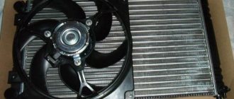
Before dealing with a radiator that isn't working, it's important for many to know the cost of the components and labor.
A new element will cost about 1.5-2.5 thousand rubles today, depending on the model and region. The cost of replacement at a service station will be from 400 rubles or more. Although you don't need to spend money on this, since replacing it yourself will take no more than half an hour. And there is nothing particularly difficult here.
temperature sensor
The fan does not work - we change it ourselves
Try to do this: you need to remove the negative terminal from the battery (the key is “10”), and then disconnect the motor connector.
Fan power connector
If you now connect the battery again, you can call “+12” on one of the two terminals. Now you can go all-in: the negative cord from the fan is connected to ground using a T-connector. Often on the VAZ-2114 hatchback the fan does not work because it is not the wiring that is faulty, but the motor. And then they perform the replacement.
Dismantling, all steps
Once again, make sure that you have disconnected the battery. Disconnect the connector as discussed above. Next, use a socket wrench to unscrew the two nuts holding the “stopper” (see photo).
Retaining bracket above the casing
There are four nuts at the corners of the plastic frame. They need to be unscrewed with a 10mm key.
One of four nuts
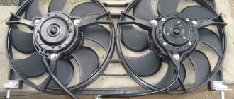
The mounting frame together with the fan is removed in the “up” direction. As you can see, everything is simple.
Installation of the unit is carried out in the reverse order. It will be possible to replace both the motor and the casing frame.
Articles
- 2108-1309010 – casing;
- 2109-1308008 (-01, -02) – motor assembled with impeller;
- 2103-1308010-10 – impeller;
- 12605571 – lock washer;
- 16102311 – M8 nut.
Installing a forced fan button for VAZ 2114
You should start work by disconnecting the ground terminal from the battery so that a short circuit does not occur during the connection of the electrical circuit. The procedure for installing the button is as follows:
- Prepare a block to which the button for forced activation of the VAZ 2114 fan will be connected. To do this, you need to leave 4 terminals with wires on it: two central ones for illuminating the button and two corner ones for controlling the power circuit of the electromagnetic relay.
- Connect two wires with lugs to the electric fan power wires that go to relay K1 (pins 30 and 87). To do this, you need to strip off some of the insulation on the wires approaching the relay and screw the pieces of wire that will go to the relay to them. Ideally, it is better to solder the connection, but you can get by with just a tight twist. The connection points must be carefully insulated.
- Connect the tips of the connected wires to the relay block to pins 30 and 87.
- Connect the control wire from the button block to terminal 85 of the relay, and connect terminal 86 with a wire to the vehicle ground. Install the fan switch button into a free slot on the dashboard, having first removed the plug.
- Install the relay in a convenient place, for example, under the dashboard of a car, and secure it.
- Connect ground to the battery.
- Turn on the ignition and press the fan button. The relay should click and the fan motor should turn on.
This completes the installation of the forced fan button on the VAZ 2114.
Conclusions: what exactly should be done if the fan does not work (action algorithm)
First, check whether the “plus” is connected to one of the terminals in the connector. Then connect the connector from ground to check the serviceability of the electric motor. In some cases, you can observe this:
- Both fuse F5 and the additional fuse are working;
- The fan relay operates as expected;
- The DTOZh sensor is working;
- The motor can only be turned on by applying a potential of “0 Volt”.
There will be only one conclusion: the ground contact has come loose, which ends the entire power line. This means you will need to contact an auto electrician. All other faults can be overcome by yourself.
Element F5 may burn out as a result of the horn closing. But then “+12” is not called up on the connector, which should immediately alert you.
leon1193 › Blog › Decoding the fuse box VAZ 2109-2114
Decoding the fuse block VAZ 2109 F9 (7.5 A)
Right fog light and fog light warning lamp
F8 (7.5 A
) Left fog light fuse
F1 (10 A)
Headlight wiper motors (at the moment of switching on), headlight wiper switch relay (contacts) and headlight washer switch valve
F7 (30 A)
Electric motors headlight cleaners (in operating mode).
Relay for turning on headlight wipers (winding). Electric motor for heater fan, washer pump, rear window wiper. Rear window washer timing relay. Rear window washer activation valve. Relay for the electric radiator cooling fan (winding) and for turning on the rear window heating. Indicator lamp for turning on the heated rear window and glove compartment lighting F16 (15 A)
Turn indicators, relay-breaker for turn indicators and hazard warning lights (in turn indicator mode).
Indicator lamp for turning on the turn signal. Rear lights (high-speed running lights). Windshield wiper motor and relay. Generator excitation winding (when starting the engine) and brake fluid level warning lamp F16 (15 A)
Fuse VAZ 2109 warning lamps: emergency oil pressure, closing the carburetor air damper, turning on the handbrake.
“STOP” display. Coolant temperature and fuel level indicators. Indicator lamp for reserve fuel remaining. Voltmeter. “CHECK ENGINE” indicator light. “TEST” board. Warning lamps for the on-board monitoring system, seat belts not fastened and doors not closed. Power circuit for inertial door lock switch F3 (10 A)
Rear lights (brake signal lamps).
Interior lighting F6 (30 A)
Electric window motor, power window relay
F10 (7.5 A)
License plate lights.
Engine compartment lamp. Instrument lighting lamps. Indicator lamp for turning on the side light. Heater lever illumination display. Cigarette lighter lamp Left headlight (side light). Left rear light - side light F5 (20 A)
Radiator cooling fan electric motor and its activation relay (contacts).
Sound signal and relay for its activation F11 (7.5 A)
Right headlight (side light).
Right rear light (side light) F2 (10 A)
Direction indicators, relay-breaker for direction indicators and hazard warning lights (in hazard warning mode).
Hazard warning light F4 (20 A)
Rear window heating element.
Relay for turning on the heated rear window (contacts). Socket for connecting a portable lamp. Cigarette lighter F15 (7.5 A)
Right headlight (high beam)
F14 (7.5 A)
Left headlight (high beam).
Indicator lamp for high beam headlights F13 (7.5 A)
Left headlight (low beam)
F12 (7.5 A)
Right headlight (low beam)
1 (8 A)
Reserve fuse in the VAZ 2109 block
2 (8 A)
Reserve
3 (8 A)
Electric motors of headlight wipers at the moment of switching on).
Relay for turning on headlight wipers (contacts). Headlight washer activation valve 4 (16 A)
Headlight wiper motors (in operating mode).
Relay for turning on headlight wipers (winding). Heater fan motor. Electric motors for the rear window washer and wiper pump. Rear window washer timing relay. Valve for turning on the windshield and rear window washer. Relay for the electric radiator cooling fan (winding) and for turning on the rear window heating. Indicator lamp for turning on the heated rear window and glove compartment lighting 5 (8 A)
Turn indicators, relay-breaker for turn indicators and hazard warning lights (in turn indicator mode).
Indicator lamp for turning on the turn signal. Rear lights (high-speed running lights). Windshield wiper motor and relay. Generator excitation winding (when starting the engine). Brake fluid level warning lamp. Indicator lamp for emergency oil pressure. Indicator lamp for covering the carburetor air damper. Indicator lamp for turning on the hand brake. “STOP” display. Coolant temperature gauge. Fuel level indicator. Indicator lamp for reserve fuel remaining. Voltmeter 6 (8 A)
Fuse for rear lights (brake signal lamps) in block 2109. Interior lighting
7 (8 A)
License plate lights.
Engine compartment lamp. Instrument lighting lamps. Indicator lamp for external lighting. Heater lever illumination display. Cigarette lighter lamp 8 (16 A)
Radiator cooling fan electric motor and its activation relay (contacts).
Sound signal and relay for its activation 9 (8 A)
Left headlight (side light).
Left rear light (side light) 10 (8 A)
Right headlight (side light).
Right rear light (side light) 11 (8 A)
Direction indicators, hazard warning relay-breaker (in hazard warning mode).
Hazard warning light 12 (16 A)
Rear window heating element.
Relay for turning on the heated rear window (contacts). Cartridge for connecting a portable lamp. Cigarette lighter 13 (8 A)
Right headlight (high beam)
14 (8 A)
Left headlight (high beam).
Indicator lamp for high beam headlights 15 (8 A)
Left headlight (low beam)
16 (8 A)
Right headlight (low beam)
Malfunction
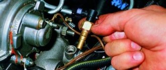
These components do not have a specific service life. They will last a long time if you follow the recommendations for using the vehicle and its systems provided by the manufacturer, follow assembly rules and buy spare parts made from high-quality materials. Spare parts are sensitive to high temperatures; this should be taken into account if the vehicle is used in hot weather conditions. If there are connection problems, then checking the sensor is not difficult - you just need to know where this device is located. It is located on the outlet pipe.
If the question arises of how to check the operation of the ventilation and what breakdowns may occur, then it will be difficult to answer.
Defects
- cracking;
- oxidation of contacts;
- broken cables;
- damage to fasteners;
- contamination of components;
- short circuit;
- microprocessor melting;
- fusion of plastic elements.
Fault indication
- continuous operation of ventilation when the engine is running;
- no fan response after the temperature rises or the air conditioner is activated;
- deterioration in vehicle controllability;
- reduction in the efficiency of the air conditioner.
Causes of failure
- influence of humidity;
- using vehicles on bad roads;
- voltage instability in the electrical network;
- low quality components;
- incorrect installation;
- violation of water tightness;
- frequent overheating.
If the fan turns on, then everything is fine.
Reasons for fan failure
There are a number of reasons why the fan sensor can eventually fail other than the sensor itself. Therefore, they should first be excluded to make sure that the sensor is to blame.
Reasons for fan failure include:
- The fan has failed. It can wear out, lose integrity, and receive mechanical damage. It will be more expensive to replace it compared to the sensor, but there is no choice.
- The chain has broken. When testing a sensor, the method of closing two of its contacts is usually used. But if the wiring circuit is damaged, this will not be possible, and due to inexperience, all the blame will be placed on the regulator.
Replacement
On an injection engine, which is literally filled with all kinds of sensors, sometimes you need to pay attention to the fan control. If the check shows that the device is faulty, there is nothing left to do but carry out the replacement procedure.
The work requires only a few tools and materials:
- 30 mm socket wrench;
- Container for draining the cooling liquid;
- Dry rags.
Having prepared everything you need, you can start replacing.
The first priority is to let the engine cool. Working on a cold engine is more convenient and safer. If hot coolant comes into contact with your skin, burns will occur.
- To replace, you do not need an inspection hole or overpass. For such work, these elements are not needed. A simple garage will do.
- Disconnect the negative terminal from the battery.
- Drain all coolant from the radiator. Do not drain the coolant from the cylinder block; this is not necessary.
- Remove the plug from the expansion tank of the cooling system of your injection engine.
- To drain antifreeze or antifreeze, unscrew the drain plug on the radiator. You will find it at the bottom of the radiator, and no tools are required for dismantling. The plug is easily unscrewed by hand.
- Place a pre-prepared container under the drain hole where the coolant will drain. Wait until the fluid flow stops completely.
- If you want to refill the same antifreeze, take a clean container. If the coolant is old enough and needs to be replaced, then the cleanliness of the container does not matter.
- Screw the plug back in.
- Disconnect the contacts from the fan sensor.
- Using a 30 mm wrench, the regulator is unscrewed.
- Twist carefully so as not to damage the plastic radiator container.
- Screw the new regulator in place of the old one. Be sure to insert a copper spacer under the new device.
Copper gasket in place
- Reinstall the fan control wiring.
- Fill the expansion tank with pre-drained antifreeze or antifreeze.
- Purge the system to avoid the formation of air pockets inside the system.
- Replace the negative battery terminal.
- Turn on the power unit and warm it up for a while to make sure the new sensor is working.
- If, when heated to the desired temperature, the sensor does not work again, you should check other elements that may be causing this behavior of the cooling system.
Replacement without draining coolant
If you do not want to spend a lot of time replacing the sensor on your VAZ 2114, you can do without the procedure of draining the coolant.
Replacing the fan control switch without the coolant drain stage requires experience and certain skills. Therefore, it is not recommended for a beginner to use this repair method.
- Using a 30mm wrench, start unscrewing the old sensor, but not all the way.
- Prepare a new sensor.
- Unscrew the old regulator completely with one hand, and quickly insert the new one with the other.
- In this case, a certain part of the antifreeze will leak out, but this is not scary.
- After replacement, be sure to thoroughly wipe all areas around the regulator with a dry cloth.
- Make sure there are no leaks after installing a new device.
Sensor check
First, we advise you to check the sensor that you think is faulty. Even if it turns out that it doesn't really work, at least you'll have peace of mind.
Plus, be sure to check the new sensor before installing it. This will make sure it works. Today there are quite a lot of fakes on the market, so there is always a chance to purchase a low-quality fan sensor.
To check you will need a certain set of tools and materials, which includes:
- Capacity;
- Water;
- Coolant;
- Thermometer;
- Multimeter.
- Pour water or regular coolant into the prepared container.
- Lower the sensor into it with the threaded part.
- Connect the multimeter terminal to the regulator contacts. The measuring device must be in resistance measurement mode. Although if the multimeter has a dialing function, then choose it.
- Place a thermometer into the liquid.
- Heat the water.
- When the liquid temperature reaches the regulator response temperature (92 degrees Celsius), the contacts should close and the multimeter will start beeping.
- If this does not happen, the sensor really does not work and needs a replacement.
If you purchased a regulator that is not working, be sure to go to the store and ask for a replacement or refund. But only if you have a receipt. It is better to purchase spare parts in specialized, good stores. There is less risk of getting caught by a fake.