Electrical diagram of Daewoo Nexia
The Daewoo Nexia electrical circuit diagram of which is presented in this section was not developed yesterday, and this greatly facilitates the repair of the main components of the car. The design of the car as a whole repeats the Opel Cadet of the 80s. Minor changes have been made to decorative elements and optics, and there are also options with a twin-shaft 16-valve engine, which in no way affected the electrical diagram that we posted below.
As you can see, the scheme is simple and to some extent identical to VAZ cars, and those who are familiar with the old Cadet will understand it without any difficulty.
Engine diagram
Elements of the F16D3 electronic engine control system:
This memory is volatile, i.e. When the electrical power is interrupted (the battery is disconnected or the wiring harness block is disconnected from the ECU), its contents are erased. The PROM stores the engine control program, which contains a sequence of operating commands (algorithms) and calibration data - settings. The PROM is non-volatile, i.e. The contents of the memory do not change when the power is turned off.
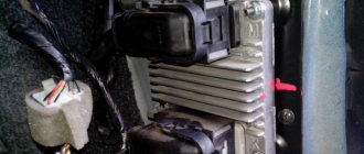
The ECU receives information from system sensors and controls actuators such as the fuel pump and injectors, ignition coil, idle speed control, oxygen concentration sensor heating element, canister purge valve, exhaust gas recirculation valve, intake tract length variable valve (on the F16D3 engine ), air conditioning compressor clutch, cooling fan.
Nexia fuse box
As in all European cars of those times, the Nexia has a fuse block with fork-type fuses. This is much more convenient than the old cartridge elements. Each fuse is responsible for a specific section of the circuit. In the event of an overload or short circuit, the fuse does not allow harm to electrical equipment located in the circuit after it. The basic rule, which cannot be neglected, is that any use of jumpers that short-circuit the contacts tightly, or bugs, is unacceptable. It is also unacceptable to use fuses that do not correspond to the rating. If the fuse has a resistance lower than the rated value, it will blow, and if it is significantly higher, it will burn out the equipment that it was supposed to protect.
For ease of use, fuses have housings of different colors. 10 amp fuses have a red body, 20 amp yellow, 30 amp fuses have a green body. The fuse board is located in the same housing as the relay block, and the entire mounting block is located on the driver's side under the instrument panel.
Explanations for symbols on electrical circuits of daewoo matiz | automotive wiring diagrams
At first glance, the electrical circuit diagrams discussed in the Matiz car section cause complete confusion. After the general diagrams of domestic cars that are familiar to us, the diagrams of foreign cars are a dark forest. However, this is not quite true. Taking the circuit apart into parts has its advantages.
And if you carefully study this section on reading electrical circuits, then everything becomes clear and simple. Take, for example, power circuits. If you do not know whether power is or should not be supplied at the moment to the section of the circuit under study, voltage.
Just look at the designation of the power cord and compare it with the table below. Let's say you're looking at a light switch circuit, you look at the diagram and it's connected to wire number 30.
This means that power, its positive source, regardless of the position of the key in the ignition switch, is constantly present on this conductor. The same goes for the fuse for this circuit.
By marking it on the diagram, we find out the maximum current load that it can withstand - in this case 80 Amperes, where it is located - in this case in the fuse box in the engine compartment and through which contact - in this case 1, which connector - here as an example connector C203.
In addition, we immediately determine the color of the harness in which the desired wire is located. For specialists, it is not particularly difficult to remember the letter indices of the designations. Moreover, there are not so many of them. And in practice, understanding the diagrams every day, they quickly get used to and understand the usefulness of these notations. If you yourself want to find and fix a breakdown in any Daewoo Matiz electrical equipment circuit, this page will help you.
Problems with power windows
The build quality of the Daewoo Nexia, unfortunately, very much depends on the factory at which the car was assembled. Most often, problems with window regulators arise on Russian-assembled Daewoos, and the components supplied to both Uzbekistan and Poland are, apparently, exactly the same. However, if problems arise with the window regulators, you need to make sure that the problem is in the electrical part. If everything is fine with the mechanics, then you should check the fuse in the mounting block.
If everything is in order with it, then most likely it is in the lift control unit. The main unit is located in the driver's door armrest. The most likely failure is failure of the control keys or lack of contact in the control unit. The fact is that the door is constantly subject to vibration, so due to poor quality assembly, the contacts may simply come off.
The starter does not turn or click, reasons
Engine failure to start is the most unpleasant situation. Especially when there is no time and there is a lot of work ahead. For Daewoo Nexia, unfortunately, starter failure has become a chronic disease. The only good thing is that any malfunction in our car can be fixed with your own hands and quickly enough. If you know where to look for the reasons.
The starter does not turn on the Nexia. Looking for reasons together
When we turn the ignition key to the starting position, we do not hear any reaction from the starter - a fairly common breakdown for Nexia. Moreover, in 80% of cases it is not the starter that is to blame, but first things first. First of all, we check the starter for performance. To do this, take a powerful short screwdriver and begin diagnostics.
- Turn on the ignition, set the gearbox to neutral and tighten the handbrake.
- Open the hood and look for the starter.
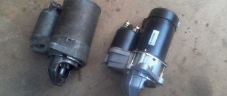
We find the starter.We clean the terminals from dirt.
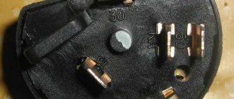
- We see three terminals - one on top and two large ones on the bottom. The upper terminal is responsible for the operation of the solenoid relay, which starts the starter motor.
- To check the retractor relay, we close the upper and positive (large, farthest from the starter housing) terminal, red arrows in the photo.
The relay should operate, the gear should engage with the flywheel, and the power contact should start the electric motor. That is, if these two terminals are closed when the ignition is on, the starter should start the engine. If the solenoid relay does not operate, the starter needs repair. Checking the solenoid relay. - If this does not happen, we close the two lower terminals, green arrows in the photo.
The starter motor should start without engaging the flywheel crown. If the electric motor is silent, then we are dealing with a short circuit in the windings or other malfunctions of the rotor or stator of the motor. Checking the starter motor.
If both tests are passed and the starter basically works, we look for the cause in the circuit before it.
Contact group - the cause of starter failure
But perhaps the most common cause of starter failure is failure of the contact group.
If the starter works by itself, as the first test showed, then with a high degree of probability the fault can be caused by the contact group of the ignition switch. The fact is that when designing the electrical circuit, the engineers did not take into account the high load on the ignition switch contacts. When starting the engine, voltage from the battery is supplied directly to the contact group and when the starter is turned on, a large current passes through the contacts, they heat up and burn out over time.
How to prevent breakage of the contact group
Of course, you can simply replace the contact group with Nexia, but there is no guarantee that the story of contact burnout will not repeat itself. To avoid problems occurring in the future, it is necessary to unload contacts 15 and 30 of the contact group. To do this, it is necessary to install an unloading relay between these contacts. A regular starter relay from a VAZ 2108, connected according to the circuit between pins 15 and 30, is suitable.
New contact group.
Starter relay - 30 A (VAZ-2108) or 50 A (VAZ-2110).
Contact terminals.
Let's understand the connection diagram: you can relieve not only the ignition circuit (pins 30 and 15), but also the starter circuit (pins 30 and 50).
We connect the wires to the terminal block.
We get to the ignition switch by removing the steering column covers.
We assemble an electrical circuit.
Checking the battery
Another reason for a non-working starter is a discharged battery or oxidized contacts at its terminals.
We check the condition of the battery, contact terminals and wires.
If a situation arises when the starter does not turn, check the voltage at the battery terminals and, if necessary, charge it. In addition, it is useful to check the contact density on the positive terminal of the starter itself. The battery terminals are cleaned and lubricated with conductive lubricant, the contact of the positive wire is cleaned and tightened tightly. This way you can avoid problems with starting the engine in the future. Instant launches and sunny roads to everyone!
carfrance.ru
Air conditioning Daewoo Nexia
Some Nexia cars were equipped with air conditioning. It was included in the most expensive configurations and worked quite reliably with proper maintenance and operation. The main reasons for the failure of the air conditioner, which relate to electrical equipment, were failures of the electromechanical clutch of the compressor drive and breakdowns of the climate control system. Despite the fairly reliable design of the air conditioner itself, there were annoying errors when assembling components, which sometimes led to premature wear of the compressor and evaporator.
Since the operation of the air conditioner is connected to the heating and blowing system, it could not help but respond to frequent failures of the air circulation drive motor. The engine itself cannot be repaired, but before you say goodbye to it, it’s worth checking the circuit right down to the fuses. If there is voltage on the circuit after the fuse, it is quite possible that the contacts in the motor power supply are to blame.
Daewoo Nexia heater diagram. Purpose of the main components of the stove
How to completely or partially change the daewoo nexia and matiz ignition switch (cylinder, contact group)?
The design for heating the Daewoo Nexia interior is represented by the following elements.
- Heater radiator (heat exchanger). Its purpose is determined by heating the air necessary for heating the interior, as well as blowing the inside of the glass in it. The air is heated through heat exchange between the walls of the radiator and the heated liquid from the cooling system of the power unit.
- An air flow blower inside the machine, which is a regular fan (an electric motor with an impeller attached to its shaft). This element is necessary for controlled air supply to the dampers of the stove or air conditioner. By the way, the latter can only work when the supercharger is turned on.
- The thermostat damper, which regulates the air flows passing through the heater radiator and bypassing it. Thus, their heating temperature increases or decreases. It is located in the common module of the stove and air conditioner.
- An actuator element for controlling air flows, which allows you to divide it, directing it, for example, to heating the foot area or blowing windows, heating the rear of the cabin, etc. They are also located in a common module, blocking or opening the heater heater lines.
- Pipes, hoses, heat lines, control rods. Their purpose is to recirculate the working fluid, transport the coolant inside the car, and control the operation of the stove.
Interior heating Nexia has a common control panel with air conditioning, which is located on the dashboard and contains the following controls and switches:
- fan position switch, which allows you to select the required rotation speed of its shaft, thereby reducing or increasing the amount of airflow.
- recirculation mode switch.
- Temperature regulator.
- air conditioner switch.
- heater actuator control regulator.
The operation of the switch that controls the blower modes is not affected by the position of the thermostat knobs, as well as the heater damper. The fan rotation speed is regulated by changing the voltage supplied to the terminals of its electric drive. The position of the heater dampers is changed using a pneumatic drive, and the thermostat is connected to its actuator through a traction connection (cable).
Ignition system
The contactless ignition system of the Daewoo Nexia works stably and there are no outright complaints about it. In the event that all elements are serviced and checked for mechanical integrity in a timely manner. First of all, this applies to highly loaded devices:
- ignition distributor;
- coils;
- high voltage circuit;
- electronic control unit.
Since 2008, an ECU without feedback has been installed on the car, so its operation has become more stable. In addition to all other corrective functions, the ECU also controls the operation of the ignition system. The control unit adjusts the operation of the system based on the following data:
- crankshaft rotation speed;
- throttle opening angle;
- data from the catalytic converter oxygen sensor;
- temperature and pressure of incoming air.
The ignition system must quickly respond to ECU signals and make adjustments to the advance angle. In case of any abnormal readings, the system informs the driver about the need for maintenance or repair.
Thus, any faults in the electrical equipment of the Daewoo Nexia can be localized, and the diagram posted on the page will help with this. Control the on-board voltage, and have a good trip!
Engine device
All daewoo nexia engines installed on the car were a classic gasoline 4-cylinder, in-line, four-stroke unit. Structurally, the engines were identical, had the same lubrication system, cooling system, and cylinder block. The engine marked G15MF also had a number of significant differences from the Opel Kadett E
The gas distribution system used a scheme with an overhead arrangement of one camshaft. The catalytic converter and lambda probe were missing.
In the newer modification, labeled A15MF, minor design changes were applied. The gas distribution mechanism was driven by two overhead camshafts. The number of valves was increased to 4 per cylinder, and the ignition system was significantly changed. A lambda probe and a catalytic converter were installed on the power plant.
The engine control system consists of an electronic control unit (ECU), sensors for engine and vehicle operating parameters, as well as actuators. The ECU is a special-purpose mini-computer. It consists of random access memory (RAM) and programmable read-only memory (PROM). RAM is used by the microprocessor to temporarily store current information about engine operation (measured parameters) and calculated data. From RAM, the engine control unit takes programs and initial data for processing. Codes of any faults that occur are also recorded in RAM.
Electrical diagrams of Daewoo Nexia N100-N150
On our website you can download in good quality all the diagrams of the Daewoo Nexia - from engine elements to electrical equipment. The photographs are color and high resolution - to do this, first left-click to enlarge the diagram and then save it to your computer. First, a little history of the car. See the second part of the article - diagrams of Daewoo Nexia systems.
Electrical equipment
Nexia engine 16 valves, timing, characteristics, main problems.
Daewoo Nexia 16 valve At first, a lot of complaints were caused by the Check Engine light, which suddenly came on and did not go out, despite any tricks. Let us reassure you right away - as a rule, there is nothing criminal, the reason is a controller glitch. The controller simply “did not see” the engine crankshaft position sensor (error P13360). It could only be cured at the dealer, and often by replacing the controller itself. By the beginning of 2009, the plant had overcome the problem. If you get a Check Engine light today, it's most likely due to low-quality gasoline.
Relays, sensors and other electrical devices are manufactured in various parts of our planet, from Kaluga and Pskov to India. Alas, at first they could not boast of either quality or maintainability. Thus, the instrument cluster, made in India, suffered from “stuck” arrows. A phantom malfunction sometimes appeared on both the new Nexia and on a car that had run more than tens of thousands of km. This did not change the essence of the matter: we had to wait at least two to three months for the “socket”. In 2009, complaints about Indian devices reached a critical mass, and at the urgent request of the manufacturer, the Indians finally got down to business. As a result, by 2010, cases of freezing became rare.
History of Daewoo Nexia
In the history of the Daewoo Nexia car there were only two generations: Nexia 1 (N100) and Nexia 2 (N150). The first generation of the car was produced from 1994 to 2008, and the second, after a slight restyling of the interior and body and a complete replacement of the engine with engines from Chevrolet Lanos and Lacetti cars, has been produced since 2008 to this day. Today we will focus on the Daewoo Nexia N100, describe its characteristics a little and give all the electrical circuits of the equipment.
The basis for the creation of the Daewoo Nexia was the Opel Kadett, which was produced in 1984–1991. As you can see, Nexia was developed by the German concern Opel. Next, the South Korean company Daewoo modernized the car and released this particular miracle car, which, due to its low cost, is produced after restyling to this day. The assembly of the car was carried out on the territory of Uzbekistan - Asaka.
The car was made in both sedan and hatchback body styles (3-door and 5-door). Only gasoline engines were offered to choose from:
- G15MF - 1498 cm3 (75 hp)
- A15MF - 1498 cm3 (85 hp)
- F16D3 - 1597 cm3 (109 hp)
- A15SMS - 1498 cm3 (80 hp)
Transmission: 5-speed manual or 3-speed automatic.
Video - crash test of Daewoo Nexia:
This is probably the toughest crash test... the car was 100% disgraced in terms of safety.
Technical characteristics of Daewoo Nexia 1 and 2:
Daewoo Nexia up to 2008. Service and repair manual
Operation of any Daewoo Nexia car is impossible without knowledge of its structure, maintenance and repair features. It doesn’t matter who will carry out the necessary work - every driver is simply obliged to know the basic maintenance and troubleshooting procedures.
The Daewoo Nexia repair book contains all the necessary information that will help the owner understand the structure of the car, teach how to properly care for the car, timely maintenance and proper repairs.
Read more: How to change the Hyundai Solaris radio
The Daewoo Nexia repair manual is divided into chapters: Vehicle design (describes general information and vehicle specifications); Operating instructions (preparation for departure, recommendations for traffic safety); Malfunctions along the way (tips to help you in case of an unexpected breakdown on the road); Maintenance (detailed recommendations for all maintenance procedures); Repair instructions (engine, transmission, chassis, steering, brake system, and also includes assembly and disassembly work necessary during the repair process of Daewoo Nexia); Electrical equipment (detailed manual for diagnosing and troubleshooting, separately describing the main units and providing detailed electrical diagrams of the Daewoo Nexia).
Any of the Daewoo Nexia repair procedures is presented according to the principle from simple to complex: from the simplest maintenance operations, adjustments, replacement of parts, to global repairs with assembly and disassembly work.
All materials in the book are based on specific experience gained in the process of complete disassembly and reassembly of the Daewoo Nexia by highly qualified auto mechanics.
The book “Daewoo Nexia up to 2008. Service and Repair Manual” is necessary so that diagnostics and repairs of Daewoo Nexia can be done professionally and quickly even by the owner of the car who still has little practical experience.
You can download the Daewoo Nexia repair manual for free in pdf format. You just need to download it to your phone or tablet and you can use it in any situation on the road.
We study the electrical circuit of the electrical equipment of Daewoo Nexia and Matiz cars
The electrical network in any car is used to connect all devices and equipment into one circuit. Therefore, every car owner must be able to understand the circuits and know about equipment malfunctions in order to make repairs on their own if necessary. You can learn more about what the electrical circuit of the Daewoo Nexia is and what malfunctions are typical for it in this article.
Some features of the functioning of heating and recirculation systems Daewoo Nexia
Note that when the recirculation mode is turned on for a long period of time, the condition of the driver and passengers may worsen due to the accumulation of carbon dioxide compounds in the cabin. Therefore, it is recommended to use this mode only as a last resort (moving through areas with heavy smoke). Therefore, when the need to use autonomous ventilation passes, the recirculation mode should be turned off. It is also not recommended to use it at low ambient temperatures, since condensation will accumulate on the glass in the cabin, which will immediately turn into ice. One of the peculiarities of the air conditioner is that it will not turn on if the heater fan position switch is set to mode “0”, that is, off. This is not considered a problem.
Features of electrical equipment
The general electrical circuit of a Daewoo Matiz or Nexia car includes the following subsystems:
- The ignition system includes a lock, a starter unit, a generator unit and a battery.
- Temperature controller, pressure and speed sensors, XX valve, dampers.
- Diagnostic unit, as well as torque converter blocking, fuel pump electric motor.
- Anti-theft system, immobilizer, central locking.
- Transmission control unit.
- Security system, including airbags, sensors.
- Lighting devices - fog lights, brake lights, headlights, headlights, interior lights, etc.
- Sound signal.
- Trunk lock, warning buzzer mechanism.
- Rear window defogger.
- Electric windows.
- Ventilation system, including stove, air conditioner.
- The dashboard, where the main parameters of the car are displayed.
- Anti-lock braking system.
- Headlight adjustment mechanism.
- A mounting block with fuses, where all safety devices designed to protect circuits are concentrated.
Fuse diagram
Ignition switch daewoo nexia and matiz: replacement of assembly, contact group and cylinder
The standard electrical circuit is deciphered as follows:
- F1 – ECU system, protects the power cores of the device;
- F2 – system of dimensions;
- F3 – not used;
- F4 – head optics high beam mode fuse;
- F5/6 – low beam, correction of the right and left headlights, respectively;
- F7 – fuel system;
- F8 – turns in operating mode, emergency lights and stops;
- F9 – wipers;
- F10 – protective element of the electric lock of the windshield lid;
- F11 – air conditioning compressor;
- F12 – low rotation speed of the stove fan;
- F13 – fuse F13 is multifunctional, the element is responsible for the cigarette lighter, instrument panel, and works as an auxiliary element of the generator circuit;
- F14 – horn and heater fan;
- F15 – interior lighting of the interior, glove compartment and cargo compartment;
- F16 – power supply for electric door windows;
- F17 – comes into operation when the tape recorder is powered from the ignition switch;
- F18 – central locking, radio power supply from battery, luggage compartment lid lock drive.
There are also several relays here.
- Maximum operating mode of the stove fan.
- Turn signals in blinking mode.
- Fuel pump switch relay.
- Front and rear fog lights.
When installing powerful optics, the foglight switch often burns out or fails to cope. To unload the element, users install an auxiliary unit and energize the rear lights to it.
The additional part contains a small number of fuse links:
- F20 – climate control;
- F21 – standard fog lights.
Drivers deal with a constantly burning element in the same way as with a relay. A separate line is drawn and powered through a common switch.
How to determine the malfunction?
One of the most common wiring problems is current leakage.
As a rule, the diagnosis of such a malfunction is carried out using the negative terminal from the battery, while the positive terminal must remain connected:
- The tester (multimeter) needs to be connected with one probe to the negative terminal of the battery, and the second probe is connected to the removed terminal block. When connected, values should appear on the tester screen - the optimal indicator in this case is a current in the region of 15-70 mA, this parameter depends on the number of voltage consumers connected to the battery. If we are talking about a car with a carburetor engine, equipped with basic equipment and without an anti-theft system, then the leakage current will be small.
- If the diagnostics show that the leakage readings are within the normal range, then the battery needs to be diagnosed. If the current consumption is increased, then the check continues, now we work with the fuse block. The safety elements are removed from this device, and after each is removed, the leakage is measured.
- If it happens that after removing the fuse, the leakage rate decreases to the optimal level, this indicates that the circuit with the fuse removed is consuming more current. Now you only need to find out which consumers are connected to this section of the electrical circuit, after which the wiring itself is diagnosed (Video author - Alexander Shestopalov).
If the battery is faulty, energy consumers may not work at full capacity, and if the battery is completely discharged, then the engine will not be able to start. It is necessary to diagnose the battery from time to time - check its voltage, measure the level and density of the electrolyte in the jars, and inspect the case. If there are cracks in the case, it is possible that electrolyte is leaking out of them, which contributes to the destruction of the battery.
You also need to pay attention to diagnosing the performance of the generator unit. If this device is not working properly, it will not be able to charge the car battery when the engine is running.
To diagnose the generator, you will need a tester - a multimeter; you need to switch it to ohmmeter mode, and then perform the following steps:
- The tester probes are connected to the battery observing polarity.
- The engine starts, after which it is necessary to set the crankshaft rotation speed to medium, turn on the music and optics. This way you can create operating conditions for the motor, under which the battery voltage is measured.
- After this, it is necessary to take readings from the tester. If the generator unit is in working condition, the voltage parameter at the battery terminals should be about 13.5-14.5 volts. If this value is lower, then the device needs to be checked in more detail (video author - Dmitry Pristrom).
Where are the fuse box and relays of the Niva Chevrolet
The location of the inserts on cars did not change from 2011 to 2022.
To gain access to the main unit, you should pick the instrument panel in the area of the pedal assembly. Under the dashboard, to the left of the steering wheel. To get to the panel under the tidy, use a Phillips screwdriver to remove the plastic casing, where the panel will be.
A detailed location with a description is in the photo below.
Chevrolet Niva fuses with description
The main elements of a car can be divided into two groups based on location. Consequently, their purpose will be different.
The photo shows a fuse panel, relevant for models manufactured after 2009. For convenience, it is better to give the decoding in the form of a table.
| Number | Circuit Description |
| F1 | License plate lighting, side lights on the left side of the car. |
| F2-4 | The main lighting is low beam, high beam and fog lamps on the left side of the car. In some configurations, fuse No. 4 is a spare socket. |
| F5 | Main power window protection relay |
| F6 | Cigarette lighter power supply. Some motorists connect power cores here instead of an incandescent filament. |
| F7 | Horn connection relay. |
| F8 | Heated rear glass and rear view mirrors. |
| F9 | Interior lighting switch, glove compartment lighting, wiper drive and electrics. Separate outlet for windshield washer system compressor. |
| F10 | Standard control module for electrical accessories and door locking, or spare |
| F11-14 | Exterior car lighting. Low and high beam head optics, fog lights, side lights. The fuses are responsible for the right side of the vehicle. |
| F15 | Standard control system for rear view mirror drives. Fuse for heated seats. The minimum configuration does not include the insert. |
| F16 | Hazard warning light breakers and turn relays |
| F17 | Interior lighting, partial display of the instrument panel, alarm position control, brake signals, additional stop block. |
| F18 | Power heating fan |
| F19 | Starter head relay, instrument panel lighting and indication, turn signal relay system in turn mode. |
| F20 | Rear fog lamps, immobilizer and anti-theft alarm buzzer. |
The car radio and speedometer are connected separately from the main fuses. The drives of the injectors and air conditioning compressor are designed similarly. Depending on the configuration and year of manufacture, the listed components may be connected according to a different scheme.
Also in the VAZ 2123 panel there are spare fuses located in separate sockets.
Additional fuse block
Here the main part is represented by relays, but there are also fuses. Fuse links have markings and areas of responsibility:
- No. 2 – high-power fuse responsible for protecting the power lines of the electrical circuit of the right radiator fan and an additional relay group;
- No. 3 – safety insert for the fuel pump located in the tank;
- No. 4 – the element is responsible for powering the car controller circuit;
- No. 9 – fuse for the right radiator fan;
- No. 10 – insert protecting power lines and circuits switched on by the main relay.
Relay Niva Chevrolet
Two places where protective inserts of electrical circuits are concentrated are presented. The explanation of the automatic circuit switching nodes is as follows.
Main mounting block.
| Designation in the diagram | Decoding of the serviced circuit and equipment |
| K1 | Mostly not used, but in some configurations it can be connected. |
| K2 | Window cleaning system, relay powers electric motor. |
| K3 | Turn signal breaker in working position |
| K4 | Headlight module - low beam switching on |
| K5 | Protective switch for turning on and powering the high beam head optics |
| K6 | An additional relay is responsible for the operation of several nodes simultaneously. Typically, the heated glass of the aft part, the fan drive of the heating system, and the windshield and rear window washers are connected here. |
| K7 | In some configurations it acts as a fuse for the heating element of the cargo compartment door. |
| K8 | Not used |
The car’s design also includes a remote control panel:
- K1/2 – standard fog lights (if equipped);
- K3 – activation of the seat heating system;
- K4 – horn protection;
- K5 – standard inclusion of the starter circuit.
Separately, you should consider the engine control system unit:
- K1 – additional relay;
- K5-6 – head radiator fan inserts for the left and right sides, respectively;
- K7 – power supply to the fuel pump circuit;
- K8 is the main relay of the car.
Possible wiring faults
What malfunctions can occur in the operation of the electrical circuit:
- Broken wiring. This problem can lead to current leakage; we have already described its diagnosis in more detail. To prevent wiring breakage when laying new wires, they must be additionally insulated.
- Short circuit. One of the less common problems is diagnosed using the same tester.
- Voltage fluctuations - it can be either low or high. Such malfunctions are usually associated with incorrect operation of the battery or generator, or, less often, additional devices.
- Contacts are oxidized or burned. Contacts usually oxidize as a result of prolonged use or when equipment operates in humid conditions. Oxidation can occur on the connecting plugs - this problem is solved by cleaning them with sandpaper or a wire brush. If we are talking about burning, then it is most likely caused by power surges in the network. Therefore, you first need to solve the problem with overvoltage, and then change the burnt contacts.
Basic engine malfunctions
Daewoo power units have a number of characteristic disadvantages:
| Characteristic disadvantages | Causes | Solution |
| Increased oil consumption | Piston ring wear Oil pump wear Leak in the motor | Replace rings Replace oil pump Replace sealing elements, tighten bolts |
| Strong knocking sound (engine is warm) | The clearances in the main bearings are larger than necessary Drive belt tension increased The torque converter is loose | Replace earbuds Adjust tension, replace if necessary Adjust bolts |
| Knock in the engine after starting | Front main bearing - increased clearance Crankshaft - increased axial clearance Hydraulic valve lifters are faulty | Replace Shaft support bearing - replace Check, replace if necessary |
| Engine heats up quickly | Thermostat is faulty | Check, replace if necessary |
| The motor takes a long time to warm up | Thermostat is faulty | Check, replace if necessary |
Most such work may require special tools, equipment, and knowledge.
Ignition system of Daewoo Nexia with 8 valve engines
Daewoo Nexia
This ignition system, as stated above, is non-contact with a centrifugal distributor. That is, the system must necessarily consist of a distributor, a switch and an ignition coil. The distributor is attached to the cylinder head and connected to the camshaft
When purchasing parts for the distributor, I noticed that almost everywhere they sell a “Hall sensor” for distributors. The same statement can be found on many sites on the Internet.
But this statement is not true. An inductive sensor is installed in the distributor, that is, a coil on a magnetic circuit in the middle of which a permanent magnet rotates. In this case, an alternating voltage of approximately 3V is induced in the coil. This signal is fed to a switch, which converts the signal and, depending on it, controls the ignition coil. The switch is located inside the distributor.
Video text
How to adjust Daewoo nexia headlights (Where and what to turn)
Adjusting the headlights of the Daewoo Nexia, instructions for dummies. Do not criticize too much) 1) To adjust the light beam of the headlight up or down, you can turn the bolt on the corrector by hand. 2) To adjust the beam to the left or right you will need a long thin screwdriver. Or you can remove the headlight and simply twist the bolt with a Phillips screwdriver.
We will be glad to see your likes and comments
subscribe to the channel
modernizatsiya chiroqlar Daewoo nexia, bu headlights ishlash Daewoo Nexia, ornatu faralar Daewoo nexia, retteu headlights Daewoo Nexia, adjust the headlights Daewoo nexia, adjust the headlights Daewoo Nexia, adjust the headlights Daewoo nexia, adjust the headlights Daewoo Nexia, kudo tas Chehi Far Daewoo Nexia,
We install fog lights on Daewoo Nexia N150 in garage conditions
The only thing that is required from the owner of a Daewoo Nexia who has decided to install fog lights on his own car is to purchase a universal kit and check its completeness.
In the photo - Nexia with branded PTF
Specifically speaking, check if the box contains:
- Two branded fog lights for Nexia N150;
- Incandescent lamps;
- Wiring harness with female terminals already installed;
- Fuse with socket for installation;
- Relay for controlling the operation of fog lights;
- PTF activation button for the interior;
- Plastic clamps and screws as fasteners.
Branded fog lights Nexia N150
Advice: specifically universal kits are better, since their developers include several spare fasteners, and the wiring is made with an allowance.