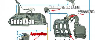
What is the mass air flow sensor, a valuable structural part of the car. This indicator is necessary for the electronic device that controls the motor. To monitor the correct amount of air being supplied. In this case, it is the air that is combustible for the fuel mixture. The sensors come in different designs, but their failure will lead to a malfunction of the main operating process of the car.
DMRV what is it
In modern cars, engines are equipped with gasoline injection devices. Therefore, it is necessary to use special measuring sensors - mass air flow sensors. Modern air flow indicators are installed on diesel and gasoline engines.
What is DMRV
Modern engines use two types of power supply systems: with distributed injection, the nozzle supplies fuel to the intake pipe, with direct injection, it supplies fuel to the combustion chamber. For both systems, the correct operation of the mass air flow sensor, which was once mechanical (vane type), but is now devoid of moving mechanical parts and made hot-wire (from “anemo” - wind), is important.
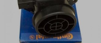
Factory air flow sensor made in Germany for a VAZ engine
The mass air flow sensor can be installed not only on a gasoline engine, but also on a diesel engine, where the operation of the EGR valve (exhaust gas recirculation system) is “tied” to it.
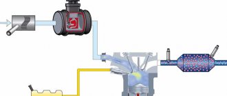
As old-school drivers used to say, an internal combustion engine does not work in two cases: there is nothing to burn or there is nothing to set it on fire. The mass air flow sensor precisely informs the electronic control unit about the amount of incoming air, the oxygen of which becomes the “fuel” for the working mixture. Having received such a signal, the ECU can ensure the most complete combustion possible. The device, located in the intake tract, consists of two resistors, which can be designed in various designs. In the first case, the resistor is exposed to passing air: when the flow intensity changes, it cools and its internal resistance changes. In the second case, it is not blown - based on the difference in readings from two resistors, the volume of air that needs to be supplied to the cylinders is calculated.
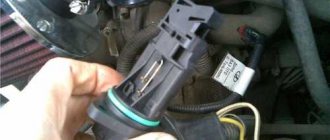
The sensor is supplied to the aftermarket with protective caps to prevent contamination during transportation.
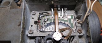
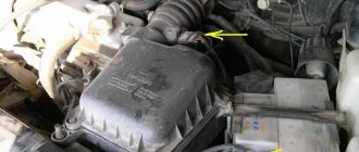
This is what the sensor looks like on a regular VAZ engine. It will not be possible to remove it from the case without a special key.
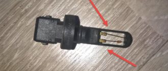
The removed sensor is in its “bare” state. The sensitive element is clearly visible
Based on the data on the mass and temperature of the incoming air, the ECU determines its density, and also calculates the duration of opening of the injectors and the amount of fuel supplied to the combustion chamber. In general, the mass air flow sensor is important for achieving maximum engine power, for more complete combustion (environmentally friendly), and for economical driving. The failure of this sensor, like most others, causes the Check Engine warning light to go off.
The check engine light can come on for any reason. If there is no on-board computer with a diagnostic function, you will have to go to a service station where there is a scanner
However, the owner does not always associate the triggered “check” with the mass air flow sensor - especially if the engine runs without any interruptions, and the dynamic characteristics of the car have not deteriorated at all. Therefore, it is important not to leave the illuminated engine malfunction indicator unattended, but to consider errors with the diagnostic computer.
What does the MAF or DMR sensor do?
MAF is a mass air flow sensor (abbreviated as MAF), it measures the volume and density of air entering the engine . Some also measure the temperature of the air entering the engine.
The computer uses this measurement along with other inputs to calculate the best air-fuel ratio and timing the ignition to suit engine operating conditions. On a vehicle with an automatic transmission, the MAF sensor can also help determine shift timing.
MAF sensor location
The MAF is located between the air filter box and the throttle body. On some models, the sensor is located inside the air filter housing.
Flowmeter design
Knowing the design of the air sensor, you will quickly understand the principle of its operation and understand why a faulty meter cannot be repaired, but only replaced. The device is not difficult to find - it is built into the air duct connecting the filter - air flow purifier with the throttle valve block. The exact location depends on the make and model of the car.
The majority of vehicles in use are equipped with hot-wire or film meters. The difference is in the design of the sensing element; the operating principle remains unchanged. An anemometer flow meter is a housing in which 2 platinum threads are placed - a measuring and a reference. How does the mass air flow sensor function in a car:
- The controller supplies power to both threads. As they heat up, they change resistance equally.
- When the engine is running, the first thread is washed by air passing through the throttle and cooled. The stronger the air flow, the more intense the cooling.
- The electronic unit records the difference in resistance between the measuring and reference threads. Having made the calculation, the ECU determines the mass of passing air and directs the corresponding amount of fuel to the injectors.
Reference. In modern cars with turbocharged engines, mass flow sensors are replaced by absolute pressure meters (MAP) - more reliable devices with a long service life. Manufacturers began to equip new naturally aspirated engines with similar products.
The film measuring device operates on the same principle, only instead of threads, platinum-coated ceramic elements are used. That is why it is quite possible to check the mass air flow sensor, but not to repair it. A burnt thread or damaged coating cannot be replaced, only the entire product.
Types of mass air flow sensors
Although there are two common types of MAF, hot wire and hot film, the most common types are hot wire. Test procedures for troubleshooting hot wire sensors may vary depending on the make of vehicle. You can further categorize MAF sensors into low frequency, voltage and high frequency types.
Some car models use a MAF that sends a voltage signal to the computer. But later models may use a voltage frequency signal.
Where is the MAF located?
The mass air flow sensor is located in the vehicle's intake tract, between the air filter and the throttle valve, and is mounted directly on the air filter housing.
Types of mass air flow sensors, their design features and operating principle
Three types of VU meters are most widespread:
Wire or thread. Film. Volumetric.
In the first two, the operating principle is based on obtaining information about the mass of the air flow by measuring its temperature. The latter may involve two accounting options:
Wire sensors
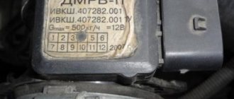
Until recently, thread mass air flow sensor was the most common type of sensor installed on domestic cars of the GAZ and VAZ model range. An example of a wire flow meter design is shown below.
Design of volumetric meter IVKSH 407282.000
Designations:
A – Electronic board. B – Connector for connecting the mass air flow sensor to the computer. C – CO adjustment. D – Flow meter housing. E – Ring. F – Platinum wire. G – Resistor for temperature compensation. N – Ring holder. I – Electronic board casing.
Operating principle and example of a functional diagram of a filament VU meter.
Having understood the design of the device, let's move on to the principle of its operation, it is based on the hot-wire method, in which a thermistor (RT), heated by the current passing through it, is placed in the air flow. Under its influence, the heat transfer changes, and, accordingly, the resistance RT, which makes it possible to calculate the volumetric flow rate of the air mixture? using King's equation:
I2*R=(K1+K2*⎷Q)*(T1-T2) ,
where I is the current passing through RT and heating it to temperature T1. In this case, T2 is the ambient temperature, and K1 and K2 are constant coefficients.
Based on the above formula, you can derive the volumetric air flow rate:
Q = (1/K2)*(I2*RT/(T1 - T2) - K1)
An example of a functional diagram with bridge connection of thermoelements is shown below.
Typical functional diagram of a wire mass air flow sensor
Designations:
Q - measured air flow. U – signal amplifier. RT - thermal resistance wire, usually made of platinum or tungsten filament, the thickness of which is in the range of 5.0-20.0 microns. RR – temperature compensator. R1-R3 are ordinary resistances.
When the flow velocity is close to zero, the RT is heated to a certain temperature by the current passing through it, which allows the bridge to be kept in equilibrium. As soon as the flow of the air mixture increases, the thermistor begins to cool, which leads to a change in its internal resistance, and, as a result, an imbalance in the bridge circuit. As a result of this process, a current is generated at the output of the amplifier unit, which partially passes through the temperature compensator, which leads to the release of heat and makes it possible to compensate for its loss from the flow of the air mixture and restores the balance of the bridge.
The described process allows you to calculate the flow rate of the air mixture based on the amount of current passing through the bridge. In order for the signal to be perceived by the ECU, it is converted into a digital or analog format. The first allows you to determine the flow rate by the frequency of the output voltage, the second - by its level.
This implementation has a significant drawback - a high temperature error, so many manufacturers add a thermistor similar to the main one to the design, but do not expose it to air flow.
During operation, dust or dirt deposits may accumulate on the wire thermistor; to prevent this, this element is subjected to short-term high-temperature heating. It is performed after the internal combustion engine is turned off.
Film air meters
A film MAF works on the same principle as a filament one. The main differences lie in the design. In particular, silicon crystal is used instead of platinum filament resistance wire. It is coated with several layers of platinum plating, each of which plays a specific functional role, namely:
Temperature sensor. Thermal resistances (usually there are two of them). Heating (compensation) resistor.
This crystal is installed in a protective casing and placed in a special channel through which the air mixture passes. The geometry of the channel is designed in such a way that temperature measurements are taken not only from the input flow, but also from the reflected flow. Thanks to the created conditions, a high speed of movement of the air mixture is achieved, which does not contribute to the deposition of dust or dirt on the protective housing of the crystal.
Design features of film mass air flow sensor
Designations:
A – Flow meter body into which the measuring device (E) is inserted. B – Contacts of the connector that connects to the ECU. C – Sensitive element (silicon crystal with several layers of coating, placed in a protective casing). D – Electronic controller, with the help of which preliminary processing of signals is carried out. E – Body of the measuring device. F - Channel configured to take thermal readings from the reflected and input flow. G – Measured flow of air mixture.
As mentioned above, the operating principles of filament and film sensors are similar. That is, the sensitive element is initially heated to temperature. The flow of the air mixture cools the thermoelement, which makes it possible to calculate the mass of the air mixture passing through the sensor.
As in filament devices, the output signal can be analog or converted to digital format using an ADC.
It should be noted that the error of filament VU meters is about 1%; for film analogues this parameter is about 4%. However, most manufacturers have switched to film sensors. This is explained both by the lower cost of the latter and by the expanded functionality of the ECUs that process information from these devices. These factors overshadowed the accuracy of the instruments and their speed.
It should be noted that thanks to the development of flash microcontroller manufacturing technology, as well as the introduction of new solutions, it was possible to significantly reduce the error and increase the performance of film structures.
Vane type air flow sensor
The design of the sensor, which has long been obsolete, is based on a pitot tube. The sensor is based on a softly fixed plate, which is deformed under air pressure. The plate resembles a blade and therefore the type of these flowmeters began to be called bladed. The blade is rigidly connected to the potentiometer (resistor) and any deformation changes the resistance of the resistor; the throttle valve works in much the same way. The control unit program contains a calibration table for the dependence of resistance on the strength of the air flow and on this basis the amount of passing air is calculated.
A vane-type sensor was used on a single injection and its feature was the ability to cure and restore the resistive layer of the potentiometer. With the development and improvement of the car and its control systems, the requirements for a more accurate determination of mass air flow have become more stringent. As a result, hot-wire sensors have been developed.
What is a flow meter
As stated above, flow meters are designed to indicate the volume and regulate the air consumed by the engine. Before moving on to a description of the principle of their operation, it is necessary to touch upon the issue of types. After all, his work will depend on this.
Types of flow meters
Flow meter appearance
The very first models were mechanical and were installed on the following fuel injection systems:
- Jetronic distributed injection;
- combined electronic injection and electronic ignition system Motronic;
- K-Jetronic;
- KE-Jetronic;
- L-Jetronic.
The body of a mechanical flow meter contains a damping chamber, a measuring valve, a return spring, a damping valve, a potentiometer, and a bypass (bypass) with an adjustable regulator.
In addition to mechanical flow meters, there are also the following types of more advanced devices:
- heated filament flow meter;
- flow meter with film hot-wire anemometer;
- flow meter with thick-walled diaphragm;
- manifold air pressure sensor.
Next, let's look at the operating principle of the listed devices.
Operating principle of the flow meter
Mechanical flow meter diagram. 1 – voltage supply from the electronic control unit; 2 – incoming air temperature sensor; 3 – air supply from the air filter; 4 – spiral spring; 5 – damping chamber; 6 – damping chamber damper; 7 – air supply to the throttle valve; 8 – air pressure damper; 9 – bypass channel; 10 – potentiometer
Let's start with a mechanical flow meter . Its operating principle is based on how much the measuring damper will move depending on the volume of air it passes through. On the same axis as the measuring damper there is also a damping damper and a potentiometer (adjustable voltage divider). The latter is made in the form of an electronic circuit with soldered resistor tracks. In the process of turning the damper, the slider moves along them, and thus the resistance changes. Accordingly, the voltage transmitted by the potentiometer is measured in accordance with positive feedback and transmitted to the electronic control unit. To adjust the operation of the potentiometer, an intake air temperature sensor is also included in its circuit.
However, mechanical flowmeters are now considered obsolete as they have been replaced by their electronic counterparts. They do not have moving mechanical parts, therefore they are more reliable, give a more accurate result, and their operation does not depend on the temperature of the intake air.
Another name for such flow meters is mass air flow sensor . In turn, they are divided into two types depending on the sensing element used:
- wire (Hot Wire MAF Sensor);
- film (Hot Film Air Flow Sensor, HFM).
MAF (mass air flow sensor)
More details
Air flow meter with wire heating element (filament). 1 – temperature sensor; 2 – sensor ring with a wire heating element; 3 – precision rheostat; Qm – mass air flow per unit time
The operation of devices of the first type is based on the use of a heated platinum filament . The electrical circuit constantly maintains the thread in a heated state (platinum was chosen due to the fact that the metal has low resistivity, does not oxidize and is not susceptible to aggressive chemical factors). The design provides that the passing air cools its surface. The electrical circuit has negative feedback, whereby as the filament cools, more electrical current is supplied to it in order to maintain the temperature at a constant level.
The circuit also contains a converter, whose task is to convert the value of the changing current into a potential difference, that is, voltage. There is a nonlinear exponential relationship between the obtained voltage value and the volume of air passed through. The exact formula is programmed into the ECU, and in accordance with it, it decides how much air is needed at a given time.
The design of the wire flow meter implies a so-called self-cleaning mode. In this case, the platinum thread is heated to a temperature of +1000°C. As a result of heating, various chemical elements, including dust, evaporate from its surface. However, as a result of such heating, the thickness of the thread gradually decreases. This leads, firstly, to errors in the sensor readings, and secondly, to gradual wear of the thread itself.
Diagram of a mass air flow meter with a film hot-wire anemometer. 1 - electrical connector leads, 2 - measuring pipe or air filter housing, 3 - computing circuit (hybrid circuit), 4 - air inlet, 5 - sensor sensing element, 6 - air outlet, 7 - bypass channel, 8 - sensor housing.
Now let's look at the operation of the film mass air flow sensor . They come in two types - with a film hot-wire anemometer and based on a thick-walled diaphragm. Let's start the description with the first one.
It is the result of the evolution of the wire flowmeter, but instead of wire, in this case a silicon crystal is used as a sensing element, onto the surface of which several layers of platinum are soldered, used as resistors. In particular:
- heating resistor;
- two thermal resistors;
- intake air temperature sensor resistor.
By analogy with a wire flow meter, the sensing element is located in a channel through which air passes. It is in a constantly heated state thanks to the use of a heating resistor.
When air enters the channel, it changes its temperature, which is recorded using thermistors installed at both ends of the channel. The difference in their readings at the two ends of the diaphragm is a potential difference, that is, a constant voltage (ranging from 0 to 5 V). Most often, this analog signal is digitized in the form of electrical impulses that are transmitted directly to the vehicle's ECU.
As for the second type of film flowmeter, they are based on the use of a thick-walled diaphragm located on a ceramic base.
The principle of measuring air mass flow with a film hot-wire anemometer. 1 – temperature characteristic in the absence of air flow 2 – temperature characteristic in the presence of air flow; 3 – sensitive element of the sensor; 4 – heating zone; 5 – sensor diaphragm; 6 – sensor with measuring pipe; 7 – air flow; M1, M2 – measurement points, T1, T2 – temperature values at measurement points M1 and M2; ΔT – temperature difference
Its active sensor detects changes in air vacuum in the intake manifold based on the deformation of the film diaphragm. With significant deformation, a corresponding dome with a diameter of 3...5 mm and a height of about 100 microns is obtained. Inside there are piezoelectric elements that convert mechanical effects into electrical signals, which are subsequently transmitted to the ECU.
Modern cars that use electronic ignition use air pressure sensors , which are considered more technologically advanced than classic flow meters operating according to the schemes described above. The sensor is located in the manifold and determines the pressure and load of the engine, as well as the amount of gases recirculated. In particular, it is connected to the intake manifold using a vacuum hose. During operation, a vacuum occurs in the collector, which acts on the sensor membrane. Directly on the membrane there are strain gauges, whose electrical resistance changes depending on the position of the membrane.
The sensor's operating algorithm consists of comparing atmospheric pressure and pressure on the membrane. The larger it is, the greater the change in resistance, and therefore the voltage supplied to the ECU. The sensor's power supply is 5 V DC, and the control signal is a pulse with a constant voltage from 1 to 4.5 V (in the first case, this is engine idling, in the second, engine operation at maximum load). The ECU directly calculates the mass amount of air, also based on the density of the air, its temperature, as well as the number of revolutions of the crankshaft.
Due to the fact that the mass air flow sensor is a rather vulnerable device and often fails, since approximately the beginning of the 2000s, automakers began to abandon its use in favor of using engines with an air pressure sensor.
Film air flow meter. 1 – measuring circuit; 2 – diaphragm; 3 – reference pressure chamber; 4 – measuring elements; 5 – ceramic substrate
Using the received data, the electronic control unit adjusts the following parameters. For gasoline engines:
- fuel injection timing;
- its quantity;
- moment of ignition initiation;
- algorithm of operation of the gasoline vapor recovery system.
For diesels:
- fuel injection timing;
- algorithm of operation of the exhaust gas recirculation system.
As you can see, the sensor design is simple, but it performs a number of key functions, without which the operation of internal combustion engines would be impossible. Now let's move on to considering the signs and causes of malfunctions of this unit.
Interchangeability
This issue is quite relevant, especially taking into account the cost of original products from the imported automobile industry. But it’s not so simple here; let’s give an example. In the first production models of the Gorky Automobile Plant, the injection Volgas were equipped with a BOSCH air flow sensor. Somewhat later, imported sensors and controllers replaced domestic products.
A – imported filament air flow sensor manufactured by Bosh (pbt-gf30) and its domestic analogues B – JSCB “Impuls” and C – APZ
Structurally, these products were practically no different with the exception of several design features, namely:
The diameter of the wire used in a wirewound thermistor. Bosch products have a diameter of 0.07 mm, and domestic products have a diameter of 0.10 mm. The method of fastening the wire differs in the type of welding. For imported sensors this is resistance welding, for domestic products it is laser welding. Shape of a thread thermistor. Bosh has a U-shaped geometry, APZ produces devices with a V-shaped thread, and products from JSC Impulse are distinguished by the square shape of the thread suspension.
All the sensors given as an example were interchangeable until the Gorky Automobile Plant switched to film analogues. The reasons for the transition were described above.
Film air flow sensor Siemens for GAZ 31105
It makes no sense to give a domestic analogue to the sensor shown in the figure, since outwardly it is practically no different.
It should be noted that when switching from filament devices to film devices, most likely, it will be necessary to change the entire system, namely: the sensor itself, the connecting wire from it to the ECU, and, in fact, the controller itself. In some cases, the control can be adapted (reflashed) to work with another sensor. This problem is due to the fact that most filament flowmeters send analog signals, while film flowmeters send digital signals.
It should be noted that the first production VAZ cars with an injection engine were equipped with a filament air flow sensor (made by GM) with a digital output; examples include models 2107, 2109, 2110, etc. Now they are equipped with a BOSCH 0 280 218 004 mass air flow sensor.
To select analogues, you can use information from official sources or thematic forums. As an example, below is a table of the interchangeability of mass air flow sensors for VAZ cars.
Compatibility table for mass air flow sensor for the VAZ model range
The presented table clearly shows that, for example, the MAF sensor 0-280-218-116 is compatible with VAZ 21124 and 21214 engines, but is not suitable for 2114, 2112 (including those with 16 valves). Accordingly, you can find information on other VAZ models (for example, Lada Granta, Kalina, Priora, 21099, 2115, Chevrolet Niva, etc.).
As a rule, there will be no problems with other brands of cars of domestic or joint production (UAZ Patriot ZMZ 409, Daewoo Lanos or Nexia), choosing a replacement mass air flow sensor for them will not be a problem, the same applies to products of the Chinese automobile industry (KIA Ceed, Spectra, Sportage etc.). But in this case, there is a high probability that the MAF pinout may not match; a soldering iron will help correct the situation.
The situation is much more complicated with European, American and Japanese cars. Therefore, if you have a Toyota, Volkswagen Passat, Subaru, Mercedes, Ford Focus, Nissan Premiere P12, Renault Megane or another European, American or Japanese car, before replacing the mass air flow sensor, you need to carefully weigh all the solution options.
If you are interested, you can search online for an epic about an attempt to replace the “native” air meter with an analogue on a Nissan Almera H16. One attempt resulted in excessive fuel consumption even at idle.
In some cases, searching for an analogue one will be justified, especially if you take into account the cost of the “native” VU meter (for example, the BMW E160 or Nissan X-Trail T30).
Design of the mass air flow sensor
Car enthusiasts call the mass air flow sensor a flow meter; in specialized literature it is designated as a volume meter. What is actually measured inside this electronic device is not the volume of air passing through it, but its mass per unit of time, moreover, compressed.
Since Ohm's law is familiar to every school graduate, the design of the mass air flow sensor is understandable to 100% of car enthusiasts:
- the device is analogous to an anemometer that measures flow speed;
- inside a tubular housing with an air deflector and a mesh metal screen at the inlet, the sensor itself is inserted perpendicular to the flow with a connector extending outward;
- Apply a current of 500 - 1200 µA to the thread or film inside the sensor, remove the voltage value 0 - 1 V in reverse flow or 1 - 5 V in normal mode;
- when current passes, the element heats up, its resistance increases (500 - 700 Ohms), and the voltage changes accordingly;
- The air flow cools the wire, the resistance decreases, and the voltage increases.
Rice. 4 Design of filament air flow sensor
The mass air flow sensor is connected according to the diagram below:
- green – to ground;
- white-gray – output voltage;
- yellow – input signal;
- dark – output signal.
Rice. 5 DMRV connection diagram
The film MAF has a built-in platinum resistor on a ceramic plate. In a filament sensor, the resistance is made of an alloy of iridium and platinum. The first VAZ models were equipped with sensors that controlled the flow rate based on the frequency of the output signal. Currently, domestic and foreign cars have mass flow sensors that determine fuel consumption based on voltage.
Rice. 6 Film mass air flow sensor
To increase functionality, the operating sensor uses two temperature-dependent elements. Since the difference in air temperature can introduce an error into the device readings, the second thread element compensates for it by measuring the temperature of the environment. Common to all devices is the presence of an adjusting screw, which is used to adjust the CO with your own hands. The designs of different manufacturers differ in the following details:
- thread thickness – 0.07 – 1 mm;
- method of fastening the thermally dependent element - laser welding, hooking with a loop on an elastic suspension;
- thread geometry – V-shaped or U-shaped;
- The design of the stand is square, eliminating errors when rotating the element around its axis.
Rice. 7 German sensor and Russian analogue
In addition to these differences, factors to consider:
- thread devices began to be produced by Bosch and General Motors, then interchangeable analogues appeared from the APZ and JSCB Impuls plants;
- introduced a film-based air flow sensor from Siemens, which was copied by the Kaluga Research and Production Enterprise AVTEL;
- the thread is heated to 140 - 170 degrees, the film to 100 degrees;
- the accuracy of measuring film modifications is lower - 4%, for thread modifications is higher - 1%;
- The devices are interchangeable with each other, but only together with a bundle of wires, since the pinout of the wires does not match.
Rice. 8 Sensor connector
Currently, thread sensors are discontinued in Europe for a number of reasons:
- low level of manufacturability of thread production;
- the presence of corrective lambda probes;
- automatic calibration of films in blowing units.
In other words, manufacturers sacrificed speed and high accuracy for the sake of significantly reducing the cost of film mass air flow sensors.
Attention: For film sensors, the connection diagram to the MIKAS-7.1 controller, version 241.3763-31, is adopted. Filament air flow sensors MIKAS-5.4 and MIKAS-7.1 (version 241.3763-01) are used.
There is a domestically produced mass air flow sensor M with protection against overvoltage, short circuit and conducted interference.
Rice. 9 Modification of mass air flow sensor M
By default, thread sensors are based on the principle of self-cleaning of a temperature-dependent element. After stopping the engine, the ECU independently supplies current to the filament to warm it up to 1000 degrees for 1 second. The adhering dirt burns out completely.
Problems with the mass air flow sensor
Problems with the air flow sensor are common in many vehicles, including BMW, GM, Volkswagen, Mazda, Toyota, Nissan, etc. The sensor element may be dirty or damaged.
For example, in some Mazda Skyactiv engines, a faulty mass airflow sensor can cause the engine to crank but not start.
An incorrectly installed or dirty air filter can lead to faster failure of the air flow sensor. Excessive soaking of the washable air filter can also cause problems with the mass air flow sensor.
Purpose and explanation of the abbreviation
Flow meters, also known as volume meters or mass air flow meters (not to be confused with mass air flow meters and mass air flow sensors), are installed in diesel or gasoline-powered vehicles. The location of this sensor is not difficult to find, since it controls the air supply, you should look for it in the corresponding system, namely, after the air filter, on the way to the throttle valve (DZ).
Installation location of mass air flow sensor on Gazelle 405
The device is connected to the engine control unit. In cases where the mass air flow sensor is in a faulty condition or is missing, a rough calculation can be made based on the position of the air flow sensor. But with this measurement method it is impossible to ensure high accuracy, which will immediately lead to excessive fuel consumption. This once again indicates the key role of the flow meter in calculating the fuel mass supplied through the injectors.
In addition to information from the mass air flow sensor, the control unit also processes data coming from the following devices: camshaft sensor (camshaft sensor), DD (knock meter), remote sensor, cooling system temperature sensor, acidity meter (lambda probe), etc.
Signs of malfunction of the air flow sensor, error code
A dirty or faulty mass air flow sensor may not measure air flow correctly. This causes the engine computer to incorrectly calculate the amount of fuel injected.
As a result, a bad MAF sensor causes a variety of problems, including no starting, stalling, reduced power, and poor acceleration. Additionally, a faulty mass air flow sensor can cause the Check Engine or Service Engine Soon light to come on.
A problem with the MAF can also change the automatic transmission's shift setting.
When the air flow sensor signal deviates from the expected range, the ECU registers a malfunction and stores the corresponding error code by turning on the Check Engine light on the instrument panel.
This fault code can be obtained using a diagnostic scanner or an ELM327 adapter with Torque software. Typically the following error codes are associated with the mass air flow sensor:
P0100 - Mass air flow sensor, circuit malfunction; P0101 - Mass air flow sensor range/performance; P0102 - Mass air flow sensor, low signal level; P0103 - Mass air flow sensor, high signal level; P0104 - Mass air flow sensor, intermittent signal.
Trouble codes P0171 Too Lean Block 1 and P0174 Too Lean Block 2 are also often caused by a bad or dirty mass air flow sensor.
Increased fuel consumption
It is recommended to determine fuel consumption not using the on-board (trip) computer, but to measure it by decreasing fuel in the tank. For this purpose, a full tank is refueled and after 100 km of run, fuel is added to the original level. The amount of fuel added will be a real indicator of consumption per 100 km.
Difficulty starting the engine
The engine starts by cranking the starter for a long time or stalls.
Drop in dynamic performance
The car accelerates sluggishly, loses speed on inclines, requiring a shift to lower gears, and black smoke is emitted from the muffler.
The engine stalls when the car is stopped
Driving with such a malfunction is problematic, especially on busy highways. In this case, you can turn off the connector with the mass air flow sensor, switching the control system to emergency mode. The engine speed will increase to 1500 (since the TPS functionally compensates for the absence of a mass air flow sensor). Driving with a missing mass air flow sensor becomes uncomfortable, but the car will no longer stall at every intersection.
The above symptoms are indirect and cannot indicate a sensor malfunction. The final conclusion about the condition of the mass air flow sensor can be made after checking it.
Why does the air flow sensor become unusable?
The control system receives information from the fuel mass consumption indicator that air is reaching the injection devices. Then the control unit identifies the volume of fuel mass that is supplied according to these data. The most common proportion of fuel and air mass is 1 to 14. When the indicator breaks, the formation of this composite mass is disrupted and this affects the dynamic characteristics.
Adverse consequences of incorrect operation of the Fuel Flow Sensor
If the DMVR breaks down, you may notice changes in the behavior of the car. The main features are:
- Reduced car dynamics: the car accelerates poorly, its movement becomes jerky.
- The engine may stall spontaneously or fail to start. In the event of a false operation or an incorrect impulse being sent to the control unit, an excess or incomplete amount of fuel may be supplied at the start. It is clear that in this case the motor does not have enough power or there is too much of it, as a result of which it runs the risk of being flooded or simply stalling.
- The “Check Engine” error light on the dashboard starts to light up. By paying attention to this signal in time, you can avoid serious problems.
- Fuel consumption increases. If a car initially spends 10-12 liters per 100 km, and then suddenly starts to “eat” 15-20 liters of gasoline/diesel fuel, this is a reason to check the mass air flow sensor. Some cars with such a malfunction can empty the tank in a short time, and then return to normal consumption.
- Power unit vibrations. This happens when the car engine is idling or when the pedal is pressed. The threat to the car lies in a sudden increase in speed without the influence of the driver.
If any of the above described signs are detected, you should immediately contact the service for preventive maintenance of the car. In addition, the machine can only operate at low or only high speeds, which will negatively affect the condition of the engine.
Checking and repairing at home
There are eight ways to independently check amplitude and frequency mass flow sensors.
Visual inspection
In order to inspect the sensor, it must be removed. This is not difficult to do on most modern cars.
For this:
- Remove the wire from the negative terminal of the battery.
- Disconnect the connector.
- Remove the bolts.
- Unscrew the clamps.
- Carefully move the air duct and remove the sensor.
Inspect the product for damage to the housing, foreign objects, dirt and condensation. If debris is found inside, it means either the air filter has not been changed for a long time, or there is leakage at the connections.
Next, thermistors (threads or films) are checked for visible damage. If they are present, then the sensor assembly is replaced.
If dirt deposits have accumulated on the threads or film, clean them with compressed air or special products.
Do not clean your ears with cotton swabs or other similar methods. Any mechanical impact can damage them.
If traces of oil are found inside the sensor, then make sure that the level in the engine crankcase is not exceeded or that the oil trap of the crankcase ventilation system, which is located under the valve cover, is not clogged.
The principle of operation of the mass air flow sensor
At its core, mass air flow sensors are equipped with two sensitive thermistors in the form of a very thin heating metal wire. A direct current is supplied to them to heat them to the required number of degrees. One wire is in the air mass, due to the influence of air it is cooled. The second is provided with protection in the form of a screen. Thanks to this, the air cools the second thread less. Based on the difference between these two resistors, the air volume required for the smooth functioning of the engine is determined.
Flashing the ECU
The ECU is re-tested in different situations, for example, for Euro-2 when installing a catalyst blende.
If there are signs of a malfunction of the mass air flow sensor and their search does not yield results, try the following:
Prepare a small plate 1mm thick. Remove the air duct and open access to the throttle assembly. Start the car. Place a plate under the throttle valve to increase its opening angle. Engine speed should increase. Disconnect the sensor by unplugging the connector.
If the engine does not react at all, then the problem is in the ECU firmware.
Malfunction of the VAZ 2114 mass air flow sensor: causes and symptoms
A malfunction of the sensor leads to a violation of the proportions of preparation of the working fuel mixture. This will primarily affect the operation of the car’s internal combustion engine: increased fuel consumption, floating speed, etc. If the breakdown is not repaired, it will lead to more serious problems in the operation of the internal combustion engine.
The reasons for the malfunction of the VAZ 2114 mass air flow sensor can be caused by:
- clogging - the ingress of crankcase gases from the throttle valve along with air, as a result, the formation of a layer of deposits on the threads that “read” the amount of air;
- breakdown of threads - wear after the expiration of the operating life (about 100-150 thousand mileage), failure due to improper operation or due to detonation in the throttle assembly.
If we look at the VAZ 2114 air sensor, the signs of a malfunction are as follows:
- the operation of the internal combustion engine at idle is unstable (when starting before warming up, strong fluctuations in speed are observed, when adding speed with the accelerator pedal, the internal combustion engine stalls);
- When the gas is completely released, the revolutions freeze and remain for several seconds at around 2-3 thousand;
- traction disappears (power decreases, the car pulls poorly downhill and does not accelerate);
Fuel consumption increases significantly due to the low level of the air flow sensor signal; accordingly, we are talking about a fuel mixture that is more enriched with air;
- The “Check Engine” light on the instrument panel lights up.
Checking the mass air flow sensor with a multimeter
To do this, you need to turn on the tester in a mode in which constant voltage is checked. The limit value for measurements should be set to 2V.
DMRV operation diagram
Sensor pinout:
- The yellow wire is located closer to the windshield. It serves as an input for a signal from the flow meter.
- The white-gray wire is the sensor voltage output.
- The black and pink wire leads to the main relay.
- The green wire is used to ground the sensors, that is, it goes to ground.
The wires may have different colors, but their location is unchanged. To check, you need to turn on the ignition, but do not start the car. The red probe from the multimeter must be connected to the yellow wire, and the black one must be connected to ground, that is, to the green wire. We measure the voltage between these two outputs. Multimeter probes make it possible to connect without disturbing the insulation of the wires.
On the new device, the output voltage ranges from 0.996 to 1.01 V.
During operation, this voltage gradually increases and by its value one can judge the wear of the flow meter:
- if the sensor is in good condition, the voltage is from 1.01 to 1.02 V;
- in satisfactory condition - from 1.02 to 1.03 V;
- the sensor resource ends if the voltage is in the range from 1.03 to 1.04 V;
- a value in the range from 1.04 to 1.05 indicates a near-death state; if there are no contraindications, then you can continue to use the sensor;
- if the voltage exceeds 1.05 V, the mass air flow sensor requires replacement.
Indications of the ADC of the flow meter
Diagnostics of the mass air flow sensor "Tseshkoy" is not complicated and can be done with your own hands.
If there is dirt on the removed sensor, you can clean it yourself. You can use WD-40 to wash it. To clean the mass air flow sensor, you must first remove the pipe from it, and then dismantle the device itself. Inside the device there is a mesh and several wires - sensors.
They need to be sprayed with cleaning agent and washed. Then let the liquid dry. If dirt remains, the procedure should be repeated. You need to clean the pipe with the same product. It must be free of dirt and oil stains. After replacing the air filter, all parts must be returned to their place. After the cleaning procedure, the functionality of the device can be restored to 80%, the error about the reduced sensor signal level disappears (the author of the video is “24 hours”).
Flushing the sensor will help avoid costly repairs.
Determining the condition of the filament and film mass air flow sensor
As already mentioned, filament sensors are simple and trouble-free, as well as self-cleaning. To determine the condition of the mass air flow sensor, voltage measurements should be taken. To do this, you will need a multimeter: for such devices the normal value is 1V, the maximum permissible voltage is 1.3V. With film mass air flow sensors it is a little more complicated: with the same nominal value, the permissible spread is only 0.02V.
The film sensor has a voltage range that allows you not only to determine whether the sensor is working or not, but also to learn about its “intermediate” state. For example, with readings in the range of 1.040-1.049V, it is highly recommended that the car owner replace the mass air flow sensor, as it is on the verge of failure. And if the multimeter produces 1.020-1.029V, then this means that the sensor has half its service life remaining.
The second method requires measuring the maximum voltage. True, it is not applicable to turbocharged engines, but on engines with a cable throttle you only need to open it sharply. If the peak voltage does not rise to 4V, this is considered a symptom of a sensor failure. However, if we are talking about cars with an electronic throttle, then the number of Volts may not reach this mark.
Checking with a scanner
Test method:
Install a diagnostic program on your phone (smartphone), tablet or laptop computer (for example, Torque Pro, Opendiag, BMWhat, OBD Auto Doctor). Connect your mobile device or laptop to the diagnostic connector located on the vehicle's electronic control unit using a special cable, Bluetooth channel. Launch the diagnostic utility on your phone (smartphone) or computer. Wait until the program finishes scanning all vehicle components. As a result, the utility will check the serviceability of each vehicle unit. Decipher the error codes that the program will show after the diagnostics are completed.
To perform this method, testers are used:
K-Line 409/1; Scanmatic; ELM (ELM) 327; OP-COM.
Types of air flow meters
At the moment, the global auto industry has stopped at producing only two types of air flow sensors - with a high-sensitivity film element and a thin platinum thread. Despite certain design features, the principle of operation of the mass air flow sensor is absolutely identical, since the oxygen entering the manifold is fixed using a heated element.
In flowmeters with a filament, this element is heated by current and then cooled by air. Moreover, the temperature of the filament must be constant, so after cooling, a higher voltage is supplied. This allows the Volta ECU to be compared with the volume of oxygen supplied to the engine combustion chambers.
Other types of mass air flow sensors, film ones, perform their function more accurately compared to filament flow meters, because they incorporate an air temperature sensor. Structurally, they are a pair of thermistors with an intermediate heating resistor. When the air flow passes along the thermistors, it cools the first one. As a result, the air heats up slightly, and the difference in electrical resistance and temperature is recorded by the device. It is in this way that the electronic engine control unit receives information about how much oxygen enters the unit.
Checking with a motor tester (oscilloscope)
As a rule, such a check is performed at specialized car services as it requires preparation.
The motor tester is connected to the sensor and the engine starts. The connection occurs either directly or through special adapters (each brand of car may have different connectors). All data is output to the laptop.
Parameters that are checked (may differ on different car models):
The time of transition signal voltage, from the moment when it is applied after turning on the ignition until the moment when, stabilizing, it returns to normal. For example, an indicator of about 1 ms is considered normal, but 6 ms is not.
Air consumption at different engine operating modes. At idle it's 3 to 5 grams per second. The reference voltage of the sensor is 5V.
Why is MAF better or worse than DBP?
Very often, when the flow meter fails or the engine is tuned - for example, when converting an atmospheric unit to turbocharging - the mass air flow sensor is replaced with a MAP (absolute pressure sensor). Firstly, the cheapness of such an alternative is attractive, and secondly, it is not the exorbitant working life of a standard device that repels. It can fail even after 50-60 thousand kilometers, and when the number on the odometer crosses the 100 thousand km line, in the lion's share of budget foreign cars, the device installed at the factory is guaranteed to fail.
And yet, understanding the question of what a DMVR is and how it differs from an absolute pressure sensor, we will immediately note the delay in the engine’s response to opening the throttle, which is observed when using DBP. This fact is explained by a less advanced operating algorithm, as well as by the fact that not all car ECUs are able to work effectively with the latter. In addition, it will not be possible to simply replace an air flow sensor with a pressure sensor without radical modifications due to their different locations, not to mention the design differences.
In a word, those car owners who prefer not to bother too much with modifications to the power unit and replace the “dead” mass air flow sensor with a new one, rather than bother with linking the DBP with an air temperature sensor - and this is absolutely impossible to do without - do not lose anything. It is impossible to categorically say which device is structurally better. After all, there are many happy cases when a car with a “native” flow meter has covered more than one hundred thousand kilometers, and the same can be said about the absolute pressure sensor. Moreover, if the latter is included in the standard equipment of the car and, accordingly, is installed at the factory in full compliance with the technology.
| Tweet |
Checking with Vasya Diagnostic
Vasya Diagnostic is a copy of the VCDS hardware and software scanner developed by the American company Ross-Tech only with Russification. It is sold in post-Soviet countries and is popular not only among professional diagnosticians, but also among ordinary car owners.
We will not describe the capabilities of the adapter; this requires separate consideration.
To diagnose the air flow sensor, certain conditions must be met:
- The engine must be warmed up to 80 degrees.
- All consumers are turned off (climate control, heater, air conditioning, heated rear windows and others).
Check procedure:
- Install the program of the same name on your laptop.
- Connect the adapter to the diagnostic port.
- Find and go to the “Selecting a control unit” section.
- Go to section "01 - Engine Electronics".
- Go to “Fault Codes” and see what errors are displayed there.
- Go back.
- Go to "Custom Groups".
- Select the current value 213, and 211, 212 according to the passport.
- Compare the readings and if they do not match, replace the sensor.
Types of mass air flow sensors, features of their design and operation
The earliest prototypes of the air flow sensor were based on the principles of changing the resistance of a resistive component. A plate in the mechanism body bent under the force of the air mass. The more the plate was bent, the more the resistance changed. The control system received measurements of the amount of fuel mass that the engine could burn.
At the moment, a pair of metal threads is used, heated to the same temperature. The operating principle of this sensor is described above. The most recent models use platinum-coated silicon wafers. It is this plate that measures the intensity of the air flow.
Currently, only two subtypes of the Sensor are used:
- resistor threads,
- sensitive film component.
They work according to fundamentally the same scheme - they measure the amount of air mass going into the engine. Both types of indicators have their positive and negative sides.
Replacing the air flow sensor
To replace the sensor with your own hands, you need to prepare a shaped screwdriver and a “10” key.
The replacement procedure consists of the following steps:
- First you need to turn off the ignition and open the hood.
- Then you need to disconnect the negative terminal on the battery.
- At the next stage, you need to loosen the clamp with which the corrugation is attached to the mass air flow sensor.
- Next, remove the corrugation from the pipe.
- Then you need to bend the comb and disconnect the sensor connector.
Disconnecting the sensor connector
Then, using a “10” key, you need to unscrew the sensor mounting bolts to the air filter housing.
Now you can remove the mass air flow sensor.
Installing the sensor yourself is carried out in the reverse order.
Thus, if the car stalls and has all the signs of a breakdown of the mass air flow sensor, then before you start repairing it, you should check the level of its signal, it should not be low, perform a full diagnosis of the car and repair all faulty components and parts.
It is important to undergo regular vehicle inspections and perform timely maintenance, then the parts and components will last longer.
How to replace the mass air flow sensor - general provisions
The engine type and car make have an impact on the sequence of service, including changing the air flow indicator. For the most part, the mechanism involves a separate part under the hood of the car that is attached to the air purification filter. There are also indicators included in the complex module. In such a situation, replacement is only possible for the entire block.
The procedure for changing the mass air flow sensor is as follows:
- Place the car on anti-roll bars or on the handbrake.
- Raise the hood and disconnect the negative terminal of the battery.
- Unscrew the indicator or loosen its fasteners.
- Disconnect the sensor terminal from the connector.
- Install a new sensor, performing all steps in reverse order.
During operation, it is necessary to carefully maintain cleanliness so as not to disrupt the fine settings of the device. If dust or moisture gets in, they can get lost, and therefore even a new indicator will not work correctly.
How to deceive the DMRV?
To bypass the flow meter, you can install a diode instead; this is a kind of deception. For this device to work correctly, the power unit of the machine must function without interruption. If malfunctions appear in the engine, there will be no point in using blende.
To complete the task, you will need a diode element with a drawdown of 0.3 volts. The essence of its installation is to deceive the microprocessor module of the engine. You can buy such a part at any radio electronics store. The device will be used to send from the reference five volts to the signal 4.7 V. As a result, the microprocessor module will consider that the flow meter is recording a large volume of air flow.
Advantages and disadvantages of two types of mass air flow sensors
Flow meters based on sensitive films perfectly record not only the incoming oxygen flow, but also the return flow. However, if dirt or oil gets into such a sensor, it may produce incorrect data.
In filament flowmeters, all unwanted components burn out, since the filament can heat up to 500 degrees or more. In addition, such meters have a simpler design, which results in low accuracy. As a result, this type of mass flow sensor does not meet European standards in its characteristics, and traveling within the European Union in a car equipped with an engine with this flow meter is contraindicated.
To rinse or not?
Many mechanics with many years of experience and ordinary car owners are confident that a “tired” mass air flow sensor can be revived by simply washing it - that is, remove it from the body and thoroughly “spill” it with some “carb cleaner” or alcohol in about the same way as 20-30 years ago they did this with carburetor jets. In fact, there are specialized sensor cleaning compounds that have nothing in common with the deposit solvents used to flush carburetors. Therefore, the price of such “narrowly sharpened” air flow sensor cleaners is completely different - and, as one can easily assume, higher. In addition, the manufacturers of such liquids directly indicate that they will not do miracles and will not turn a “half-dead” sensor into a completely new one, but are intended for preventive flushing of working mass air flow sensors - to remove contaminants associated with dust and oil mist that has entered the intake tract from the ventilation system crankcase
Please note: for flushing, a specialized composition is used specifically for cleaning the air flow sensor, and not a universal carburetor or fuel system cleaner
Practical experience in using such “miracle remedies” shows that they can indeed slightly reduce the readings of a still working sensor, but for those that go beyond 1.05 V, such manipulations will be like a poultice for the dead...
The main thing is not to damage the removed sensor, which is afraid even of dust, not to mention mechanical impact.
Many drivers, due to inexperience, themselves destroy still living sensors when washing. Sensitive elements should not be touched with hands or wiped with a rag, and strong pressure of liquid will do nothing but harm. Therefore, cleaning the mass flow sensor in a garage should be treated with great caution and remember: if the sensor has already “died”, then this is harmless and will no longer help it, but even if it is still in good working order, this procedure may not bring a noticeable result.
How to check the air flow meter
The process of checking the air flow meter is simple and can be done in several ways. Let's look at them in more detail.
Disabling the sensor
The simplest method is to turn off the flow meter. To do this, it is necessary to disconnect the power wire suitable for the sensor (usually red and black) with the engine turned off. After this, start the engine and drive the car. If the Check Engine warning light lights up on the dashboard, the idle speed exceeds 1500 rpm, and the car's dynamics have improved, then it is highly likely that your mass air flow sensor is faulty. However, we recommend that you perform additional diagnostics.
Checking with a scanner
Another diagnostic method is using a special scanner to identify errors in car systems. Currently, there is a wide variety of such devices. More professional models are used at service stations or service centers. However, for the average car owner there is a simpler solution.
It consists of installing special software on a smartphone or tablet with the Android operating system. Using a cable and adapter, the gadget is connected to the car's ECU, and the mentioned program allows you to obtain information about the error code. To decipher them you need to use reference literature.
Popular adapters:
Adapter ELM327
- K-Line 409.1;
- ELM327;
- OP-COM.
As for software, most often car owners use the following software:
- Torque Pro;
- OBD Auto Doctor;
- ScanMaster Lite;
- BMWhat.
The most common error codes:
- P0100 - mass or volumetric air flow sensor circuit;
- P0102 - low signal level at the input of the mass or volumetric air flow sensor circuit;
- P0103 - high signal level at the input of the mass or volumetric air flow sensor circuit.
Using the listed hardware and software, you can not only search for air flow meter errors, but also make additional settings for the installed sensor or other components of the car.
Checking the flow meter using a multimeter
Checking the mass air flow sensor with a multimeter
Also popular among car enthusiasts is the method of checking the flow meter using a multimeter. Since the most popular mass air flow sensor in our country is BOSCH, the verification algorithm will be described specifically for it:
- Turn on the multimeter in DC voltage measurement mode (abbreviated as DC). Set the upper limit so that the device can detect voltages up to 2 V.
- Start the car engine and open the hood.
- Find the air flow meter directly. It is usually located on or behind the air filter housing.
- The red lead of the multimeter must be connected to the yellow wire on the sensor, and the black lead to the green one.
- If the sensor is working properly, then the voltage value on the multimeter screen should not exceed 1.05 V. If the voltage is significantly higher, it means that the sensor has completely or partially failed.
We provide you with a table that shows the value of the received voltage and the state of the sensor.
| Voltage value, V | Sensor status |
| 0,966…1,01 | Voltage value on the new mass air flow sensor |
| 1,01…1,02 | Good condition of the sensor |
| 1,02…1,03 | Average condition |
| 1,03…1,04 | Sensor life is coming to an end |
| 1,04…1,05 | Very bad condition |
| Over 1.05 | The sensor needs to be replaced urgently |
Visual inspection and cleaning of the air flow meter
If you do not have a scanner or appropriate software at hand to diagnose the condition of the mass air flow sensor, you should perform a visual inspection of it in order to identify a malfunction of the air flow meter. The fact is that there are often situations when dirt, oil or other process fluids get into its body. This results in errors in the data produced by the device.
For a visual inspection, the first step is to dismantle the flow meter. Each car model may have its own nuances, but in general the algorithm will be approximately as follows:
- Turn off the car ignition.
- Using a wrench (usually 10), disconnect the air hose through which air is supplied to it.
- Disconnect the wires listed in the previous paragraph from the sensor.
- Carefully remove the sensor without losing the O-ring.
Next, you need to conduct a visual inspection. In particular, you need to make sure that all visible contacts are in good condition and not broken or oxidized. Also check for dust, debris and process fluids both inside the housing and directly on the sensing element. Their presence may cause errors in the broadcast readings.
Accordingly, if these contaminants are detected, it is necessary to clean the housing and the sensitive element. To do this, it is best to use an air compressor and a rag ( with the exception of the film flow meter, it cannot be cleaned or blown with compressed air ).
Alcohol (ethyl or methyl) is well suited for this purpose, but it is better to use specialized MAF cleaners. Their composition does not corrode the sensitive element of the sensor. If you are using alcohol, you can draw it into a syringe and pour it over the flow meter under slight pressure. With professional sprays everything is simpler - just open the lid of the can and spray over the entire surface of the sensor. After this, the air flow sensor should dry out - leave it in a ventilated place for about 20-30 minutes.
Perform the cleaning procedure carefully so as not to damage its internal elements, especially the threads.
Results
Finally, we will give some more tips on how to extend the life of the air flow meter. First, change your air filter regularly. Otherwise, the sensor will overheat and produce incorrect data. Secondly, do not allow the engine to overheat and make sure that its cooling system is operating normally. Third, when cleaning the air flow meter, perform this procedure carefully. Unfortunately, most modern mass air flow sensors cannot be repaired, so if they fail completely or partially, they need to be replaced accordingly.
Is it possible to do without it?
Failure of the mass air flow sensor causes the check to be triggered, but the engine will continue to operate. True, depending on the newness of the ECU firmware, the “emergency” program, without seeing a signal, can raise the idle speed to approximately 1,500 rpm. On relatively new software versions, a sensor malfunction only leads to an increase in fuel consumption or a drop in dynamics. In any case, an error in the mass air flow sensor is an important reason to check it, at least by measuring the voltage.
If the mass air flow sensor does not operate correctly, the electronics may begin to over-enrich the working mixture.
The malfunction should not be ignored, since even on relatively simple cars (the front-wheel drive Lada line of the first generations), failure of the mass air flow sensor threatens a noticeable excess consumption of gasoline or a weakening of the engine’s output characteristics. That is why the answer to the popular question “Is it possible to do without a mass air flow sensor if it is included in the design of the car?” is unambiguous and sounds like this: no, you can’t.
Signs of malfunction and consequences of flow meter failure
You can judge the malfunction of the device by the following signs:
- the car is difficult to start;
- “Check Engine” is on;
- fuel is consumed in greater quantities;
- the dynamics of increasing speed limits has worsened;
- floating idle speed.
Flow meters ensure the formation of a high-quality mixture. If the device stops working correctly, the motor will lose power and driving performance will decrease. If the sensor fails completely, the engine will not start.
It is necessary to periodically diagnose the air filter. The quality of operation of the air flow sensor depends on its condition. Don't forget about the condition of the piston system. If the working mixture is released into the throttle, failure of the flow meter is inevitable.
DMRV serviceability test: testing methods
There are two ways to determine if the indicator is broken - with your own hands or with a specialist. The latter involves a trip to the service center, where they will certainly determine the malfunction. But there is a risk that they may deceive you by recommending a replacement for a completely serviceable device. In the first case, you will have to deal with the problem yourself, but everything will be as honest as possible.
Visual inspection
This stage involves a visual inspection of the air supply line for the presence of moisture and foreign contaminants. Foreign objects can clog the sensor's sensitive hole, causing it to not work properly.
Power off
When the network is turned off, the machine's control system will reconfigure itself to the emergency line and provide a fuel resource based on the throttle position. When in such a situation the motor functions accurately, then the culprit was a defect in the indicator.
Firmware test
If you have a diagnostic scanner, then you should use the device. You need to connect it to the indicator and test the device for a glitch in the firmware. If there are any, you need to reflash the indicator.
Reading faults
The newest vehicles are based on self-testing functionality. You need to put the instrument panel into test mode and read the error codes that appear on the system monitor. By deciphering them, you can understand the cause of the problem.
Changing the indicator
You can understand the performance of the indicator by replacing it with a known one. If the car stops acting up, then the indicator was broken. If the car's behavior remains unchanged, you need to look for another reason.