For those who are actively interested in various inventions, improvements and innovations in the field of engine building, you should pay attention to Ibadullayev’s engine, as well as an engine without a crankshaft.
If in the first case we are talking about a significant increase in the compression ratio and obtaining high power without increasing the working volume, then in the second we should understand a decrease in mechanical losses and an increase in efficiency, fuel consumption, degree of vibration, total weight of the internal combustion engine, etc. Let's look at the engine without a crankshaft in more detail.
A new round of internal combustion engine evolution: a super engine without a crankshaft
For those who are actively interested in various inventions, improvements and innovations in the field of engine building, you should pay attention to Ibadullayev’s engine, as well as an engine without a crankshaft.
If in the first case we are talking about a significant increase in the compression ratio and obtaining high power without increasing the working volume, then in the second we should understand a decrease in mechanical losses and an increase in efficiency, fuel consumption, degree of vibration, total weight of the internal combustion engine, etc. Let's look at the engine without a crankshaft in more detail.
Motor without a crankshaft: advantages and difficulties of implementation
So, the main task and purpose of any internal combustion engine is to convert the energy obtained from fuel combustion into mechanical work. Simply put, the fuel burns in a closed volume, the gases exert pressure on the piston, and through the crank mechanism the reciprocating motion of the piston is converted into rotational motion.
As a result, engine torque is created, which is transmitted through the transmission to the wheels of the car. It is noteworthy that although more than 100 years have passed since the creation of the first engines and their introduction to the masses, the overall design of the internal combustion engine has not changed.
Even taking into account the fact that modern engines have received high-precision, developed electronic injection and control systems, it has become possible to change valve timing, etc., the well-known crankshaft continues to form the basis of a power unit running on gasoline, diesel fuel or gas.
At the same time, work is constantly underway so that the engine can operate without a crankshaft. The fact is that the usual crank mechanism is not without a number of certain disadvantages. It is for this reason that engineers are trying to get rid of this unit.
The fact is that the operation of a crankshaft is associated with the inevitable creation of friction and significant lateral forces, which lead to wear of the cylinder walls. As a result, the cylinder mirror is damaged, the piston rings are destroyed, etc. In terms of friction losses, the overall efficiency of the engine is noticeably reduced.
Article on the topic: How to warm up the oil in the engine: available methods and solutions
Also, an engine with a crankshaft is difficult to maintain, since removing the crankshaft without removing the engine is extremely difficult to implement on many cars. It is quite obvious that if these shortcomings are eliminated, the engine will become more productive and its service life will increase.
To solve the problem, designers offer different approaches, but in practice, most solutions are simply not possible to implement efficiently. The Balandin engine and the Frolov engine deserve the greatest attention in this area today. Let's look at mechanisms without connecting rods and crankshafts in more detail.
Balandin connecting rod engine
This motor is known for the fact that it does not have connecting rods. The transformation of the reciprocating movement of the pistons in the cylinders occurs due to the use of a special eccentric mechanism in the design.
The general structure of a connecting rod engine requires the presence of the following parts:
- special piston rod
- special design crankshaft
- crank bearing and crank
- power take-off shaft
- piston
- rod slider
- cylinder
In such an internal combustion engine, instead of connecting rods, piston rods were used, which are rigidly attached to the pistons (in a conventional unit, a piston pin is used for connection). These rods, like conventional connecting rods, cover the crankshaft journals.
Also, sliders are made on the rods on both sides of the bearing. These sliders slide along special guides in the engine crankcase. As a result, this design makes it possible to relieve the piston and cylinder walls from lateral forces. In fact, in such an implementation scheme, the piston can be considered a regular holder for piston rings that seal the gap between the cylinder and the piston.
The absence of lateral forces allows for reduced tolerances on piston dimensions. The engine becomes more productive, economical, and its service life increases. It is also worth noting the compactness of such an internal combustion engine and reduced weight. However, the main disadvantage of the entire design can be considered the extremely high requirements regarding the overall manufacturing accuracy of the specified eccentric.
Article on the topic: Replacing the engine block plug
Frolov engine: motor without connecting rods and crankshaft
The main principle of V. Frolov, which was the basis for his developments, is that the crankshaft is a part that is far from perfect. For this reason, the talented engineer studied the design of Balandin’s engine in detail, after which he proposed a number of his own modifications.
Taking into account the fact that the disadvantage of Balandin’s crankless motor remained increased requirements for the accuracy of manufacturing the eccentric, at the initial stage Frolov significantly modernized this conversion unit. However, the fact was further recognized that it is extremely difficult to completely get rid of the shortcomings of the Balandin motor circuit.
We also recommend reading the article about what an FSI engine is. From this article you will learn what features engines of this type have, as well as what pros and cons this motor has.
At the same time, Frolov did not stop there, and also did not abandon the idea of getting rid of the crankshaft. Further searches for reliable and efficient conversion mechanisms led the inventor to turn his attention to the mechanism of the loom.
As a result, a segmented rotary motor was created, which was based on both borrowed and modified ideas, as well as our own ideas. The resulting engine does not have a crankshaft; instead of this part, a mechanism is used, which, in its principle of operation and its design, is similar to a hinge of different angular velocities. This device is better known as a Hooke's hinge.
The rotating parts in such a Frolov engine operate thanks to the use of rolling bearings. As for the lubrication system, engine oil is supplied under the valve covers, then drains, providing lubrication and removing excess heat. To ensure that the oil is well cooled, an oil cooler is also installed separately in front of the engine.
Share with friends on social networks:
Source: https://auto-self.ru/novyy-vitok-evolyucii-dvs-super-dvigatel-bez-kolenvala/
What's the result?
As you can see, even taking into account the complexity of implementation, engineers and designers still continue to look for ways to improve the overall reliability of engines, increase their efficiency, and reduce fuel consumption. We also recommend reading the article about what a GDI engine is. From this article you will learn about the design features, as well as the advantages and disadvantages of motors of this type.
It should also be added that Western manufacturers are also closely addressing this issue. For example, the famous Japanese corporation Toyota also offered its own version of an engine without a crankshaft. Although such a unit is more like an electric generator, it can still be considered one of the versions of an internal combustion engine.
Taking into account the above, it becomes clear that it is too early to talk about the end of the evolution of internal combustion engines. In other words, we should not exclude the possibility of the appearance of connecting rodless engines, as well as units without a crankshaft, on production vehicles.
Source: https://KrutiMotor.ru/dvigatel-bez-kolenchatogo-vala/
Piston rings
Piston rings provide a tight, moving connection between the piston and the cylinder. They prevent the breakthrough of gases from the above-piston cavity into the crankcase and the entry of oil into the combustion chamber. There are compression and oil scraper rings.
Compression rings (two or three) are installed in the upper grooves of the piston. They have a cut called a lock and can therefore spring back. In the free state, the diameter of the ring should be slightly larger than the diameter of the cylinder. When such a ring is inserted into the cylinder in a compressed state, it creates a tight connection. In order to ensure that the ring installed in the cylinder can expand when heated, there must be a gap of 0.2...0.4 mm in the lock. In order to ensure good running-in of compression rings, rings with a tapered outer surface, as well as twisting rings with a chamfer on the edge on the inside or outside, are often used on cylinders. Due to the presence of a chamfer, such rings, when installed in a cylinder, are skewed in cross-section, fitting tightly to the walls of the grooves on the piston.
Oil scraper rings (one or two) remove oil from the cylinder walls, preventing it from entering the combustion chamber. They are located on the piston under the compression rings. Typically, oil scraper rings have an annular groove on the outer cylindrical surface and radial through slots to drain oil, which passes through them to the drainage holes in the piston (see Fig. a). In addition to oil scraper rings with slots for oil drainage, composite rings with axial and radial expanders are used.
To prevent gas leakage from the combustion chamber into the crankcase through the locks of the piston rings, it is necessary to ensure that the locks of adjacent rings are not located on the same straight line.
Piston rings operate under difficult conditions. They are exposed to high temperatures, and lubrication of their outer surfaces, moving at high speed along the cylinder mirror, is not enough. Therefore, high demands are placed on the material for piston rings. Most often, high-grade alloy cast iron is used for their manufacture. Upper compression rings, which operate under the most severe conditions, are usually coated on the outside with porous chrome. Composite oil scraper rings are made of alloy steel.
Design and principle of operation of a two-stroke internal combustion engine
There are two main types of engines: two-stroke and four-stroke . In two-stroke engines, all operating cycles (the processes of inlet of the fuel mixture, exhaust gases, purge) occur during one revolution of the crankshaft in two main strokes.
Engines of this type do not have valves; their role is played by a piston, which, when moving, closes the intake, exhaust and purge windows. Therefore, they are simpler in design. The power of a two-stroke engine with the same cylinder dimensions and shaft speed is theoretically twice that of a four-stroke engine due to the greater number of operating cycles.
Alternative to overhaul
Many people prefer not to repair a worn-out engine, but to take a so-called contract (used) engine. Not a bad option, you can even save a lot of money - a complete overhaul sometimes costs twice as much. For example, the price of a “live” engine for Granta is 25–30 thousand rubles, for Logan – 45 thousand rubles. For more complex multi-cylinder engines they ask from 80 to 200 thousand rubles or more.
Internal combustion engine: design and principle of operation - Auto Moto Special
No matter how hard humanity tries to get rid of gasoline and diesel engines, which drive all transport, with the exception of trolleybuses and trams, nothing works.
There are many reasons for this, some of them are obvious, and can lead to conversations about world government and similar global things, so we will consider a more harmless topic.
It’s not why we use internal combustion engines, but why they make it possible to move quickly and safely in space.
The photo shows an internal combustion engine converting pressure from burning fuel into mechanical work
How does an internal combustion engine work?
On the one hand, everything is extremely simple - the operating principle of an internal combustion engine is based on the conversion of one type of energy into another. Namely, the energy of a heat engine capable of converting the chemical energy of gasoline, diesel fuel or natural gas into mechanical energy. ICEs exist not only in the form we are familiar with, they can also be gas turbine and rotary, but most often we use a piston engine, which proved its worth and reliability more than a hundred years ago.
The good thing about an internal combustion engine is that it can operate completely autonomously. We are used to this, and it doesn’t seem to us that this is a great advantage, but it’s worth remembering the helplessly dangling arches of a trolleybus or the dead batteries on a radio-controlled car, and autonomy becomes much more important than it seemed.
The internal combustion engine is compact, light weight and low cost, has good maintainability and can be adapted for several types of fuel at once. It has been criticized for more than a hundred years for its noise and harmful emissions, but we have learned to somehow cope with these troubles.
But in order to cope with the motor at the user level, you need to know its basic design and operating principle.
video about the principle of operation of an internal combustion engine
The piston engine is still the leader in prevalence and is under the hood of every car, under the tank of every motorcycle.
A certain Wankel tried to create an alternative rotary engine, but he was unable to bring the design to perfection, so we remember him in passing. A conventional piston internal combustion engine can run on gasoline, diesel fuel, gas, and also on alcohol compounds.
The possibility of using hydrogen as a fuel is also being considered, but this design has not become widespread, despite its environmental friendliness and promise.
Structurally, the main roles in the engine are played by the crank and gas distribution mechanisms. A number of systems strive to ensure their stable operation, the main ones being the fuel supply, lubrication, exhaust, cooling and ignition systems.
All this equipment is assembled on the basis of the most massive parts - the cylinder block and the cylinder head. Let's briefly get acquainted with the main mechanisms, otherwise it will be difficult to understand the principle of operation of the internal combustion engine.
A piston engine is found under the hood of every car today.
Volume of disasters
Capital can be partial or full. To determine what kind of repair the engine needs, it is necessary to carry out control measurements and troubleshooting - start with the condition of the cylinders and the piston play in them, inspect the liners and measure the diameter of the crankshaft journals, evaluate the gaps in the piston pins. With partial capitalization, they are usually limited to replacing piston rings, liners, seals, and gaskets. With a complete overhaul, the list turns out to be much longer, and the amount of work is significantly greater. The cost of repairs is correspondingly higher.
Full capital
The sequence of actions with full capital is as follows. First, the engine is removed from the car. This operation is most expensive on all-wheel drive vehicles with automatic transmissions.
Two-stroke engine, device, principle of operation, secrets of power
The range of applications extends to motorized units, chainsaws, small motor boats, and motorcycles. The two-stroke engine has small dimensions, high power and low efficiency. For this type of unit, fuel efficiency is fundamentally unimportant. Nowadays, they are used as starting motors to drive large diesel internal combustion engines, for example, tractors.
Device
The two-stroke engine is distinguished by its simplicity of design, the absence of a gas distribution mechanism, and its small dimensions. Structurally, the diagram is a cylinder block, inside of which the crankshaft is located on bearings.
The connecting rod head with liners rests on the shaft journal and is secured with castle nuts. The upper head of the connecting rod is connected to the piston through a metal hollow sleeve (pin).
A piston with compression rings located on it prevents the penetration of burnt gases into the combustion chamber.
By moving the piston up and down, the shaft rotates. Next, the rotation is transmitted to the main gear of a particular unit.
The two-stroke engine is cooled through the outer fins of the block.
Cooling also occurs due to fuel containing a certain amount of oil. That is, the lubrication of the piston-cylinder and crankshaft-connecting rod joints is carried out with a mixture that is diluted in advance with a special oil. When it burns with fuel, it should not leave exhaust deposits under the piston.
Principle of operation
The process is based on the duty cycle that occurs per revolution of the crankshaft. The principle of operation of a two-stroke engine is that when moving upward, the piston compresses the mixture present under the piston, which got there through the inlet port. The spark from the spark plug explodes the fuel, sharply increasing the temperature and pressure of the gases.
As a result of this thermal pressure, the piston is forced downward. At the same time, the exhaust window and a little later the transition window open, injecting a fresh portion of fuel. By the way, the fuel in a two-stroke engine must be supplemented with oil, making up a mixture of gasoline and oil of a certain proportion.
This is done to lubricate the piston, cylinder wall and crank assembly. The fuel mixture enters the crankcase through a window that opens due to the vacuum created by the movement of the piston from BDC to TDC. At the same time, the piston opens the hole, releasing the spent exhaust gases.
At a certain period, a purge window is opened by means of a piston to fill the cylinder with a fresh portion of the fuel mixture.
Power boost
To increase engine power you need:
- Increase the area of the outlet opening, keeping it in the open position for a long time in order to release the maximum amount of gases.
- Increase the efficiency of blowing. This is necessary so that fuel can be injected into the combustion chamber through the inlet ports. Otherwise, an accumulation of the fuel mixture will be observed in the crankcase. To avoid this, it is recommended to enlarge the outlet windows, which will lead to high-quality filling of the cylinder.
- Use a vortex (zero) diffuser on the carburetor, which will supply more mixture in a shorter period of time.
- Install a so-called resonator on the muffler, corresponding to the engine speed. This unit helps return a portion of the mixture back to the cylinder. Similar nuances arise when a two-stroke engine throws part of the fuel out of the chamber through the outlet (window).
To completely fill the sub-piston volume, you should also examine the condition of the inlet and outlet channels to reduce all kinds of burrs, scratches, and roughness. These casting defects contribute to slowing down the flow, reducing the filling of the chamber, and reducing power.
https://www.youtube.com/watch?v=MoFZHPS3-SU
Milling followed by fine grinding of the block head is considered to be an effective way to increase engine power. The complexity of the procedure comes down to measuring the displacement volume and selecting the octane number of the fuel.
To increase engine power, it would be possible to reduce the weight of rotating parts, for example, a flywheel, crankshaft, by cutting off the counterweight elements. But bitter experience tells us not to take the risk, since doing it on your own will lead to the flywheel beating and vibrating, especially at low engine speeds. But if you really want to, you can remove thin chips, followed by mandatory balancing of the flywheel. As for the crankshaft, there is a risk of losing the center of gravity of the shaft with all the ensuing consequences.
Piston with rings and pin
The piston is a small cylindrical part made of aluminum alloy. Its main purpose is to convert the pressure of released gases into translational motion transmitted to the connecting rod. The reciprocating movement is ensured by the sleeve.
The piston consists of a skirt, a head and a bottom (bottom). The bottom can have different shapes (convex, concave or flat), and it contains the combustion chamber. On the head there are small grooves for piston rings (oil scraper and compression).
Compression-type rings prevent possible gases from entering the engine crankcase, and low-removal type rings are designed to remove excess oil from the cylinder walls.
The skirt is equipped with special bosses with holes for installing the piston pin connecting the piston and connecting rod.
connecting rod
The connecting rod is another part of the crankshaft, which is made of steel by stamping or forging, equipped with hinged joints. The connecting rod is designed to transfer motion energy from the piston to the shaft.
The connecting rod consists of an upper, collapsible lower head and a rod. The upper head is connected to the piston pin. The lower collapsible head can be connected to the shaft journal using caps (connecting rod).
Crank (knee)
A piston connecting rod is attached to any crank (elbow). Often the crank is located from the axis of the journals within a certain radius, which determines the stroke of the piston. It was this detail that gave the name to the crank mechanism.
Crankshaft
Another moving part of a mechanism of complex configuration, made of cast iron or steel. The main purpose of the shaft is to convert the translational piston movement of the piston into rotational torque.
The crankshaft consists of journals (main, connecting rod), cheeks (connecting the journals) and counterweights. The cheeks create balance during the operation of the entire mechanism. Inside the neck and cheeks are equipped with small holes through which oil is supplied under pressure.
Flywheel
The flywheel is usually mounted at the end of the shaft. Made from cast iron. The flywheel is designed to increase uniform rotation of the shaft to start the engine using a starter.
Currently, dual-mass type flywheels are more often used - two disks that are quite tightly connected to each other.
Cylinder block
This is a stationary part of the crankshaft, which is made of cast iron or aluminum. The block is designed to guide the pistons; it is in them that the entire work process is carried out.
The cylinder block can be equipped with cooling jackets, bearing beds (camshaft and crankshaft), and mounting point.
Cylinder head
This part is equipped with a combustion chamber, passages (intake and exhaust), spark plug holes, bushings and seats. The cylinder head is made of aluminum.
Like the block, the head also has a cooling jacket that connects to the cylinder jacket. But the tightness of this connection is ensured by a special gasket.
The head is closed with a small stamped lid, and a rubber gasket that is resistant to oil is installed between them.
The piston, cylinder liner and connecting rod form what motorists commonly call a cylinder. An engine can have from one to 16, and sometimes more, cylinders. The more cylinders, the larger the total displacement of the engine and, accordingly, the greater its power. But you need to understand that simultaneously with power, fuel consumption also increases. The cylinders in the engine can be arranged in different layouts:
- in-line (the axes of all cylinders are located in the same plane)
- V-shaped layout (cylinder axes are located at an angle of 60 or 120 degrees in two planes)
- opposed layout (cylinder axes are located at an angle of 180 degrees)
- VR layout (similar to V-shaped, but the planes are located at a slight angle relative to each other)
- The W-shaped arrangement is a combination of two VR-arrangements on one crankshaft, located in a V-shape with an offset relative to the vertical
The balancing of the engine, as well as its size, depends on the layout. The boxer engine has the best balance, but it is rarely used on cars due to its design features.
The in-line six-cylinder engine also has excellent balance, but its use in modern cars is almost impossible due to its bulkiness. V-shaped and W-shaped engines are most widespread due to the best combination of dynamic characteristics and design features.
Engine without crankshaft - understanding the mechanism + video
Over the years, engineers have tried to imagine how a super engine would work without a crankshaft. After all, this would reduce fuel consumption and the degree of negative consequences of constant vibration in the engine. And it happened, the invention caused numerous discussions. Let's try to get an impression of this unit.
If we compare a car with the human body, then it is the engine that will act as the heart. Without it, operating the vehicle is simply impossible. The word motor itself, translated from Latin, means to set in motion. And in a nutshell, this device is responsible for converting energy from fuel combustion into mechanical energy, without which the car will not start.
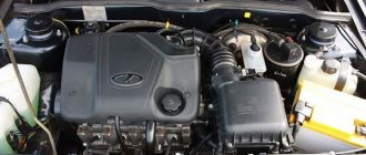
Car engine
The first time we heard about such a unit was back in 1801, and the French engineer Philippe Lebon should be thanked for this invention. But the creator of the samples closest in structure to modern engines is considered to be the self-taught German engineer Nikolaus Otto. The world learned about his achievements more than 70 years later, in 1877.
French engineer Philippe Lebon
Five years earlier, Brighton tried to implement a power unit that would run on kerosene; previous devices operated on gas. The attempt was unsuccessful. But in 1882, a new unit powered by liquid fuel – gasoline – came to life. And humanity owes its thanks to the German designer, engineer and industrialist Gottlieb Daimler for its birth.
Why do we want to get rid of the crankshaft?
More than two hundred years have passed since the appearance of the first power unit, and a lot has changed since then. Various modifications have appeared, now they run on gasoline, diesel fuel, gas, but the function and role of the engine in the structure of the car has remained unchanged. However, a significant leap occurs precisely in our century. Today, new technologies are emerging, and there are already developments of engines without a crankshaft. But how can the motor work without this unit?
Engine without crankshaft
If you look at it, the traditional crank mechanism has a number of disadvantages. For example, during its operation a very strong lateral force is created on the cylinder walls. This leads to premature piston wear. Such an effort also significantly increases friction losses, which means efficiency suffers.
To eliminate this drawback, a mechanism is needed in which the connecting rod will only perform reciprocating movements. But angular swings should be completely eliminated. Now you can find many designs of such units. Some of them have a right to exist, others are worthless.
crank mechanism
The basis of many inventions is the Balandin connecting rod engine. Its job is to transform reciprocating movements thanks to a special eccentric mechanism, to which very high demands are placed, which makes it difficult to make the motor accessible.
To date, engineers have managed to create a working engine that has passed all tests, in which the number of crankshaft bearings has been reduced. These are two-piston designs. And most likely in the coming years this sample will be put into mass production. This, of course, did not make the dream of millions a reality, but it brought us significantly closer to it.
In the meantime, an internal combustion engine without a crankshaft remains an obsession, and the search for solutions continues.
Connecting rod repair
The connecting rods of most automobile and tractor engines are made of steel 45, 40Х, 40Г, etc. The main defects of connecting rods are: bending and twisting of the rod; wear of the hole in the lower head of the connecting rod, the bushing and the hole in the upper head for the bushing; wear of the supporting surfaces of the cover for the nuts of the connecting rod bolts, etc.
Connecting rods are rejected if there are cracks, breaks, or emergency bends. In addition, connecting rods of SMD-60, SMD-64 engines and their modifications are rejected if the triangular splines on the supporting surfaces of the lower head connector are wrinkled.
The bending and torsion of the connecting rods are checked using indicator and optical devices. In general-purpose workshops, to check connecting rods, they use the KI-724 device, which is universal and allows you to control connecting rods of engines of different brands. Before checking, a frame 7 is inserted into the hole in the plate 4 of the device. In this case, the supporting surface 8 of the mandrel for the lower head of the connecting rod should be at the top, and the clamping pin 5 at the bottom. The connecting rod without the upper head bushing is fixed on the mandrel 7. A small mandrel of the device is first inserted into the hole in the upper head of the connecting rod. Having installed prism 2 on a small mandrel, move the connecting rod together with the mandrel and prism until the stop of the prism touches the surface of the plate. In this position, secure the mandrel with handle 6. Then remove the connecting rod from the device, and install the prism with the indicator on mandrel 7 and move it until the prism stop touches the surface of the plate and the indicator arrow turns 1.0-1.5 turns. In this position, the upper indicator arrow is set to zero. Rotate the prism on the mandrel so that the measuring rod of the lower indicator and the second stop are in contact with the plate, and set the arrow of the other indicator to zero.
Install the connecting rod on mandrel 7 so that its lower head rests against limiter 3. Place the prism on the small mandrel of the upper head of the connecting rod and bring it to the plate. When you touch the prism stop, the arrow of the upper indicator will show the amount of bending in hundredths of a millimeter over a length of 100 mm. Turning the prism to the other side, use the lower indicator to determine the amount of torsion of the connecting rod.
For diesel connecting rods of all brands, bending should not exceed 0.05 mm, and twisting should not exceed 0.08 mm over a length of 100 mm (the distance between the prism stop and the indicator measuring rod). The permissible bending of connecting rods of automobile engines is 0.03 mm, the permissible torsion is 0.06 mm.
Connecting rods that are bent or twisted beyond the permissible values are restored or rejected. Editing with heating of the rod with a gas burner flame to a temperature of 450-500°C is allowed. Heating relieves internal stresses in the connecting rod rod, which during engine operation tend to return the connecting rod to its original (deformed) state.
Wear of the holes in the lower head of the connecting rod is eliminated in several ways, depending on the degree of wear. Before restoration, check the supporting surfaces under the heads of the connecting rod bolts and nuts, as well as the parting planes.
The supporting surfaces are milled until signs of wear are removed. The crumpled or worn parting planes are milled or ground until the planes are parallel to the generatrix of the hole. Non-parallelism is allowed no more than 0.02 mm along the entire length of the connector planes.
If the layer of metal removed by grinding from the parting planes of the cover does not exceed 0.3 mm, and from the parting planes of the connecting rod is 0.2 mm for diesel engines and, respectively, 0.4 and 0.3 mm for carburetor engines, then the connecting rod is assembled, tighten the nuts with normal tightening force and bored, and then ground to the nominal size.
If the holes for the liners in the connecting rods are worn out so much that it is necessary to remove a layer of metal larger than indicated above from the parting planes, then the holes are restored by increasing the layer of metal (iron plating, flame spraying, etc.) followed by processing to the nominal size.
The worn hole for the bushing in the upper head of the connecting rod is bored or reamed until traces of wear are removed, and a bushing of increased size is pressed in along the outer diameter. The hole for the bushing is bored on a URB-VP-M machine or on a lathe using a special device. After boring, the bushing is rolled out using roller rolling machines on the same machines. When boring, leave a rolling allowance of 0.04-0.06 mm. The rolling process reduces surface roughness and increases the strength of the bushing fit by 70-80%.
Worn bushings of the upper head of the connecting rod are restored by compression, followed by increasing the outer surface by copper plating, upsetting in the connecting rod, thermal diffusion galvanizing, followed by mechanical processing.
FORGOTTEN GENIUS
At the beginning of his inventive career, 30 years ago, Vitaly Frolov had not yet set his sights on changing the internal combustion engine - he limited himself to the small things: he installed special linings on the crankshaft. When they wore out, I changed them along with the liners, and the shaft continued to work. Just? However, no one had thought of this before. Vitaly received the first author's certificate, he was awarded a silver medal at the Exhibition of Achievements of the National Economy of the USSR - in those days it was considered very honorable to become a laureate of this award.
This often happens: brilliant inventions are forgotten. The wonderful crankshaft was never introduced...
It seems that Vitaly’s resentment towards unreasonable humanity resulted in a dislike for crankshafts, and later he mercilessly “destroyed” the part in all his subsequent developments. And he formulated one of the principles: the crankshaft is an imperfect part.
What's the result?
As you can see, even taking into account the complexity of implementation, engineers and designers still continue to look for ways to improve the overall reliability of engines, increase their efficiency, and reduce fuel consumption.
We also recommend reading the article about what a GDI engine is. From this article you will learn about the design features, as well as the advantages and disadvantages of motors of this type. It should also be added that Western manufacturers are also closely working on this issue. For example, the famous Japanese corporation Toyota also offered its own version of an engine without a crankshaft. Although such a unit is more like an electric generator, it can still be considered one of the versions of an internal combustion engine.
Taking into account the above, it becomes clear that it is too early to talk about the end of the evolution of internal combustion engines. In other words, we should not exclude the possibility of the appearance of connecting rodless engines, as well as units without a crankshaft, on production vehicles.
Over the years, engineers have tried to imagine how a super engine would work without a crankshaft. After all, this would reduce fuel consumption and the degree of negative consequences of constant vibration in the engine. And it happened, the invention caused numerous discussions. Let's try to get an impression of this unit.
Instructions ZAZ 965A ZAZ 965AB
SHOCK ABSORBERS
Shock absorbers are used to dampen vehicle vibrations that occur when driving over uneven roads.
The shock absorbers of the front and rear suspensions are hydraulic, telescopic type, double-acting, completely identical in design and differ only in the characteristics of the compression and rebound valves (the front shock absorbers are less elastic) and the method of attaching the lower end of the front shock absorber
The shock absorber structure of the front wheel suspension is shown in Fig. 70. During vehicle operation, shock absorbers do not require any adjustments and do not need to be topped up with working fluid. However, it is necessary to periodically make sure that the shock absorbers are in good condition and check the quality of their work.
When the shock absorber is removed from the vehicle, when the rod is pulled out, it should exhibit greater resistance than when it is pushed in. Free, without resistance, movement of the rod indicates a malfunction of the shock absorber. If the shock absorber has been in a horizontal position for a long time, it must be thoroughly pumped until elasticity is restored.
Checking for tightness (no fluid leakage) must be done by periodically inspecting its tank. After the first 6000 km, it is necessary to tighten the reservoir nut on all shock absorbers. If, when driving a car, knocking noises are heard in the wheel suspension system that are not caused by malfunctions in the suspension units itself, then you should, without removing the shock absorbers from the car, make sure that there are no gaps in the hinges of their fastening.
Fig 69 A Removable trailing arm bracket (view from the body side)
a - axis of sawing the holes of the left bracket when finishing the alignment of the left wheel
b - axis for sawing the holes of the right bracket when finishing the alignment of the right wheel
B Wedge plate surfaces P and P must be flat
Rice. 70. Shock absorber:
1 - eye; 2 — bypass valve plate; 3 — intake valve spring; 4 — intake valve limiting nut; 5 - sealing ring; 6 - piston; 7— bypass valve; 8 — limiting plate of the bypass valve; 9 — rod; 10—working cylinder; 11 — tank cylinder; 12 — oil seal cage; 13 — tank nut; 14 — casing cover; 15 — thrust ring; 16 — oil seal; 17 — oil seal cage; 18 — rod seal; 19 — oil seal washer; 20 — nut seal; 21 - spring; 22 — rod guide; 23 - casing; 24 — throttle disk of the recoil valve; 25 — recoil valve disc; 26 — recoil valve plate; 27 — recoil valve spring; 28 — recoil valve adjusting washers; 29 — recoil valve nut; 30 — compression valve seat; 31 — compression valve body; 32 - compression valve spring: 33 - compression valve.
Rice. 71. Special key for disassembling shock absorbers.
In a working shock absorber, the rod moves in both directions without knocking or jamming. It should be remembered that the shock absorber has a very complex design and many precisely manufactured and assembled parts. Therefore, its disassembly should be done only in truly necessary cases, use a special tool and maintain special cleanliness. It is recommended to disassemble shock absorbers if there is no resistance to the movement of the rod, jamming of the rod, knocking noises during operation, or leakage of working fluid. need to replace the working fluid. Before disassembling the shock absorber, you need to clean its outer surfaces from dirt, wash it in gasoline (or kerosene) and wipe dry with clean rags.
Then fully extend the shock absorber piston rod, secure the lower eye in a vice, use a special wrench (Fig. 71) to unscrew the nut and remove the rod with the piston and stuffing box from the working cylinder. Next, pour out the liquid from the working cylinder and rinse the shock absorber with gasoline or kerosene, and rinse the valve assembly parts especially thoroughly.
If necessary, disassemble it. Refer disassembly to qualified personnel. Assembling the shock absorber must be done carefully and carefully so as not to damage the valve assemblies and working surfaces. If during assembly it turns out to be necessary to install a new rubber oil seal, it is recommended to first fill its grooves with a special lubricant consisting of a mixture of CIATIM-201 lubricant and 10% (by weight) powdered graphite grade P. To avoid damage, the oil seal must be mounted on the rod using a special mandrel .
Refill the shock absorber using the following method. Place the working cylinder with the compression valve body (assembled) installed in it in the reservoir and fill the working cylinder with liquid from the beaker to the top, pour the rest into the reservoir, then insert the rod with the piston into the working cylinder, close the cylinder with the rod guide and, carefully pushing the reservoir oil seal tightly to the guide, tighten the reservoir nut. In this case, the rod must be extended out of the cylinder completely until the piston stops in the rod guide.
Fill the shock absorber only with a special working fluid and in a strictly defined quantity.
To fill the shock absorber, use a mixture of 50% (by weight) turbine oil 22, GOST 32-53 with 50% transformer oil, GOST 982-56. Spindle oil AU, GOST 1642-50 can be used as a substitute. The amount of liquid to be filled in cm3 is marked on the shock absorber casing. The assembled shock absorber should be pumped, check the quiet operation and the force developed on its rod during compression.
CLICK HERE to learn how to get 21,999 visitors to your site. For free!
ziper65turbo.narod.ru