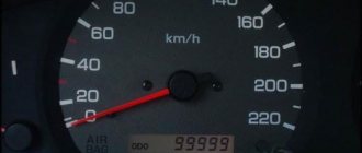
The first car from the Zhiguli family equipped with a tachometer was the VAZ 2103. Neither 2101 nor 2102 had such a device. The tachometer is used to measure the crankshaft speed. It is a revolution counter, showing their number by deflecting the scale needle to a certain angle. The tachometer is also indispensable when setting up the carburetor - its indicators are taken into account when adjusting the idle speed and the quality of the fuel mixture.
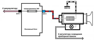
VAZ tachometer connection diagram
The first car from the Zhiguli family equipped with a tachometer was the VAZ 2103. Neither 2101 nor 2102 had such a device. The tachometer is used to measure the crankshaft speed. It is a revolution counter, showing their number by deflecting the scale needle to a certain angle. The tachometer is also indispensable when setting up the carburetor - its indicators are taken into account when adjusting the idle speed and the quality of the fuel mixture.
VAZ-2106 tachometer connection diagram
The “Sixes” were equipped with a tachometer model TX-193. This tachometer consists of:
- plastic cylindrical body with glass holder;
- a scale divided into zones of safe and dangerous modes;
- backlight lamps;
- a milliammeter with an arrow attached to its shaft;
- electronic printed circuit board.
The principle of its operation is based on measuring the number of electric current pulses in the primary (low-voltage) circuit of the car’s ignition system. In the VAZ 2106 engine, for one revolution of the distributor shaft, corresponding to two rotations of the crankshaft, the contacts in the breaker close and open exactly four times. These pulses are removed by the device from the final terminal of the primary winding of the ignition coil. Passing through the parts of the electronic board, their shape is converted from sinusoidal to rectangular, having a constant amplitude. From the board, the current flows to the winding of the milliammeter, where, depending on the pulse repetition rate, it increases or decreases. The arrow of the device reacts precisely to these changes. The greater the current, the more the arrow deviates to the right and vice versa.
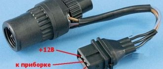
Connecting a tachometer in carburetor VAZ 2106
Electric circuit of the speed counter of the carburetor “six”
In a contactless ignition system, the tachometer is connected not to the coil, but to the switch
Connecting a tachometer in injection VAZs
It should be taken into account that the colors of the wires and their purpose may differ depending on the manufacturer of the device, but for the standard “TX-193” device, which is usually used in “sixes”, the diagram is as follows:
- A white cable is required to connect the backlight.
- The red wire is connected to the ignition switch, a fuse is used for this, this cable supplies power when the ignition is activated.
- A white cable with a black break is required for connection to the car body.
- The brown wire connects to the K+ terminal on the coil.
- The black wire is connected to the charging current indicator relay. The latter, in turn, is installed on the right in the engine compartment.
- The gray-black cable is required to connect to the engine fluid pressure regulator installed to the left of the engine.
Purpose of the tachometer
The tachometer on the VAZ 2109 is a device installed on cars to measure engine speed. Thanks to this device, the driver can find out what crankshaft speed is currently supported by the power unit. This device also allows you to prevent exceeding the possible permissible engine speed.
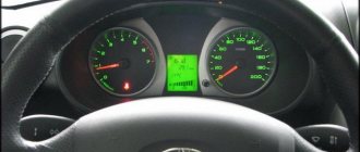
Dashboard with installed digital device
The main purpose of the tachometer on the VAZ 21099 carburetor is to facilitate the selection of the required gear, and this, in turn, makes it possible to increase the service life of the engine. At the moment when the instrument needle begins to approach the red zone, it is recommended to switch to a higher gear. This device can also be used for adjustment work while driving or when the internal combustion engine is idling.
If you decide to purchase a VAZ 2109 tachometer, first you need to decide on the type:
- Digital devices allow you to display information about the operation of the power unit on a special display. If you install this device on a VAZ 2109 carburetor, the device will be able to more accurately set the forced idle economizer thresholds.
- Analog devices are more popular today. Such devices allow you to clearly demonstrate the number of engine revolutions using a scale and an arrow that moves along it (the author of the video is Ilya Popov).
Connection diagram for tachometer VAZ-2108 and 2109
Let us immediately note that the fuel supply system – injector or carburetor – does not play a special role here. As you know, currently the most common are cars with the following engine types: gasoline or diesel. Depending on this, the tachometer is selected, unless, of course, it comes in the stock version. The thing is that on gasoline engines the tachometer reads data from the ignition coil, or rather, the impulses that arise here. However, the design of diesel power plants does not provide for this unit. Accordingly, here the tachometer reads pulses not from the ignition coil (for lack of one), but from the generator.
The first two wires (12-volt and Signal) are to contacts “B” and “K” of the ignition coil, respectively. All that remains is to secure the mass in any convenient place.
Expert recommendations
Some expert recommendations regarding diagnostics and repair of speakers:
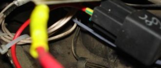
- Diagnosis of the cause of unit failure should begin with a visual inspection of the speed sensor, as well as the wiring connected to it. As practice shows, the reason often lies in a broken wiring, in particular, in the place next to the plug.
- If the controller is covered with dust or oil, you need to dismantle it and wipe it thoroughly. Then you can put the sensor in place and try to check the performance of the speaker. There is a possibility that after these steps the speaker will operate normally.
- Under no circumstances should you drive with a non-working speaker, so if problems are found in its operation and you cannot check it yourself, you need to seek help from a specialist.
VAZ-2110 tachometer connection diagram
- tachometer VAZ;
- trip computer;
- ECM;
- crankshaft position sensor;
- ignition module.
Tachometer VAZ 2110 - with four outputs: if it is on a car with injection, it is connected not to the ignition (input 2), but to the ECM controller with an additional output provided for this (input 1) - and in this case it reads the number of revolution pulses directly from the controller. It receives a signal about the position of the shaft.
About the DPKV tachometer sensor
The tachometer has a sensor (crankshaft position sensor - DPKV). This device serves not only to count crankshaft revolutions, but also to determine its position at a certain moment, which is necessary for the electronic control unit to ensure proper operation of the power unit. When a metal object passes near the sensor core, an electrical impulse is generated in it, which is transmitted to the electronic engine control unit. The role of such an object in the power unit of a car is played by the crankshaft gear.
What is a tachometer and why is it needed?
A tachometer is a device that, as I already said, shows the number of engine revolutions per minute (thousand rpm). The tachometer readings are necessary to make it easier for the driver (usually a beginner) to navigate and correctly select the desired gear (up or down). A tachometer is also necessary in order to monitor the correct operation of the engine by the number of revolutions. For example, when the speed fluctuates or is too high, a fault can be detected in time.
Why does the VAZ tachometer jump?
It often happens that the needle starts to twitch. If the car is fuel-injected, then troubleshooting involves connecting a diagnostic scanner and checking the engine systems. Jumps in the TX-193 needle in most cases are also a symptom of malfunctions associated with its electrical circuit. The reasons for this behavior of the device may be:
- lack of good contact at the negative terminal of the battery;
- oxidation or burning of the brown wire on the ignition coil;
- burning or wear of the contacts of the ignition distributor cap or slider;
- wear of the distributor shaft bearing;
- shorting the red wire powering the device to vehicle ground;
- malfunction of the crankshaft position sensor (for injection engines).
Speedometer Troubleshooting Options
Before troubleshooting, you need to find out exactly the reason why the speedometer on the VAZ 2112 does not work. There is a reliable and simple method for this. The check begins with the speed sensor and, in search of a breakdown, moves towards the speedometer.
You should make sure that all wires and devices are in good working order. To determine the presence of a signal, you can use a lamp to which wires are soldered. It can be easily connected to the vehicle's on-board network.
Check procedure:
- The first wire is connected to the negative terminal of the battery.
- The second simulates impulses, trying to touch contact “A” with a certain frequency.
- If the speedometer reacts - the arrow turns at a small angle - then this part of the electrical circuit is working.
- By touching the contacts all the way from the block to the device, you can determine where the break is located.
If the tachometer on a VAZ does not work
Usually, the lack of response from the arrow is due to a broken contact in the connectors of the main wires of its connection, or damage to the wiring of the circuit. The first step is:
- Inspect the fastening of the conductor in brown insulation to terminal “K” on the ignition coil. If you detect poor contact, traces of oxidation, burning of a wire or terminal, fix the problem by cleaning the problem areas, treating them with anti-corrosion liquid, and tightening the fastening nut.
- Check the reliability of the connection of the black and white wire to the vehicle ground. If contact is broken, clean the wire and the surface to which it is attached.
- Using a tester, determine whether voltage is supplied to the red wire when the ignition is on. If there is no voltage, check the serviceability of fuse F-9, which is responsible for the integrity of the instrument panel circuit, as well as the condition of the ignition switch contacts.
- Disassemble the instrument panel and check the connections of the contacts in the tachometer wiring harness block. “Ring” all the wires going to the device with a tester.
How to check the speed sensor
After examining the contacts and wires for oxidation, contamination, damage, if they are not found, then it is necessary to check the sensor itself. There are reliable methods for determining the performance of a device.
How to check the DS for functionality? The procedure for determining the health of the sensor can be carried out using a portable oscilloscope. It measures the signal coming from the device and displays it.
Using this method, you can visually determine not only that the sensor is faulty, but also try to determine the cause of the failure. You can get an idea of the nature of the signal using a conventional multimeter.
For diagnostics, it is necessary to connect the sensor wires to the measuring device, and rotate the device itself, holding the core. You can fix the sensor in the screwdriver sleeve. Then a rectangular image should appear on the oscilloscope screen. After one rotation, six pulses should be shown. This is what the signal from a working sensor looks like.
What the oscilloscope shows
If the speedometer on an injection-type VAZ 2110 does not work, and a signal is sent to the device, then the complaint is most likely to the speed sensor drive. If the edges of the shaft are mechanically damaged, then the functionality of the system can be restored only after replacing the DS.
Important! The DS test can be performed without dismantling the device. If you lift the front wheel with a jack, then by rotating it you can get the same effect as using a screwdriver.
The tachometer does not work on the VAZ 2110 injector reasons
REASONS FOR A NON-WORKING TACHOMETER
The tachometer in a car is used to indicate the number of revolutions of the engine crankshaft. Let's look at why the tachometer doesn't work and how to find and eliminate the cause of the breakdown. We will definitely dwell on the device and principle of operation, which will help to find out why the tachometer stopped working, the needle twitches or behaves inappropriately.
CLASSIFICATION BY OPERATING PRINCIPLE
- Mechanical or electromechanical tachometers with direct drive. The revolutions are transmitted to the dial indicator through a flexible shaft, which, through a worm gear, receives rotation directly from the crankshaft or one of the transmission shafts. The operating principle of the indicator is based on the phenomenon of eddy current induction. The operation and design of a magnetic tachometer are extremely similar to the operating principle of a car speedometer. In modern cars, a similar tachometer design is not used.
- Electric machine. A distinctive feature is the connection to a generator. It is used primarily on diesel engines, but for the purpose of unification, a device of this type can also be used on gasoline engines.
- Electronic. The signal can be taken either from the ignition system or directly from the computer. Installed on gasoline and diesel internal combustion engines.
DEVICE AND PRINCIPLE OF OPERATION
Main components of electric machine and electronic tachometers:
- measuring unit, or signal converter. It can be based on elements of analog circuitry or built using special microcircuits;
- display unit with analogue or digital display of the number of revolutions;
- auxiliary elements.
The operation of electronic tachometers is based on the conversion of individual signals or pulses captured from the computer, ignition system or generator into a signal “understandable” for the display unit.
CONNECTION DIAGRAM
When looking for the reason why the tachometer does not work, it is first of all important to understand the connection diagram and the type of signal. There are 3 typical connection schemes:
- to a contactless ignition system (the tachometer wire is connected to the primary circuit of the ignition coil). The operating principle is based on measuring the frequency of voltage surges in the primary circuit of the ignition system. Calculating the ignition angle is impossible without focusing on the number of crankshaft revolutions, therefore the sparking frequency directly depends on the crankshaft rotation speed. On 4-cylinder internal combustion engines, a full revolution of the crankshaft corresponds to 2 voltage pulses in the primary circuit. Accordingly, the higher the crankshaft rotation speed, the greater the frequency of voltage surges;
- connection to the contact ignition system. The operating principle and connection diagram are similar to the BSZ, but the design of the measuring unit will differ depending on the voltage of the input circuit;
- connection to the engine ECU. The principle of operation is still based on recording voltage pulses in the primary circuit of the ignition system, but the signal to the tachometer comes from the engine control unit;
- connection to the generator (the tachometer signal contact is connected to terminal W of the generator). The rotation of the generator pulley is carried out by a belt drive from the crankshaft, so the rotation speed of the generator rotor will always be proportional to the crankshaft speed. The change in the number of revolutions of the crankshaft can be calculated by constantly measuring the amount of EMF generated on the winding. By its operating principle, an electric machine tachometer resembles a conventional voltmeter.
Evidence of speedometer malfunction
Content
Compliance with the speed limit on the road is the main thing that is required of the driver. Stopping the operation of the device responsible for this function can lead to unpleasant consequences. Therefore, timely detection of a speedometer malfunction is important.
Certain signs will help you verify that your device is faulty:
- constant position of the speedometer needle while the car is moving;
- The speedometer on the VAZ 2110 works and does not work, its needle behaves unstable: twitching, freezing in one position;
- the arrow shows the change in speed as the engine warms up to its operating temperature, then the instrument arrow stops moving, freezing at one reading;
Uncertain behavior of the speedometer needle requires checking its serviceability, finding the cause of the breakdown, and eliminating it.
Diagnosis of the causes of breakdown of the speedometer of cars with 8 valves is similar for cases where the speedometer of the VAZ 2110 injector 16 does not work.
VAZ tachometer connection diagram
The first car from the Zhiguli family equipped with a tachometer was the VAZ 2103. Neither 2101 nor 2102 had such a device. The tachometer is used to measure the crankshaft speed. It is a revolution counter, showing their number by deflecting the scale needle to a certain angle. The tachometer is also indispensable when setting up the carburetor - its indicators are taken into account when adjusting the idle speed and the quality of the fuel mixture.
VAZ-2106 tachometer connection diagram
The “Sixes” were equipped with a tachometer model TX-193. This tachometer consists of:
- plastic cylindrical body with glass holder;
- a scale divided into zones of safe and dangerous modes;
- backlight lamps;
- a milliammeter with an arrow attached to its shaft;
- electronic printed circuit board.
The principle of its operation is based on measuring the number of electric current pulses in the primary (low-voltage) circuit of the car’s ignition system. In the VAZ 2106 engine, for one revolution of the distributor shaft, corresponding to two rotations of the crankshaft, the contacts in the breaker close and open exactly four times. These pulses are removed by the device from the final terminal of the primary winding of the ignition coil. Passing through the parts of the electronic board, their shape is converted from sinusoidal to rectangular, having a constant amplitude. From the board, the current flows to the winding of the milliammeter, where, depending on the pulse repetition rate, it increases or decreases. The arrow of the device reacts precisely to these changes. The greater the current, the more the arrow deviates to the right and vice versa.
Connecting a tachometer in carburetor VAZ 2106
Electric circuit of the speed counter of the carburetor “six”
In a contactless ignition system, the tachometer is connected not to the coil, but to the switch
Connecting a tachometer in injection VAZs
It should be taken into account that the colors of the wires and their purpose may differ depending on the manufacturer of the device, but for the standard “TX-193” device, which is usually used in “sixes”, the diagram is as follows:
- A white cable is required to connect the backlight.
- The red wire is connected to the ignition switch, a fuse is used for this, this cable supplies power when the ignition is activated.
- A white cable with a black break is required for connection to the car body.
- The brown wire connects to the K+ terminal on the coil.
- The black wire is connected to the charging current indicator relay. The latter, in turn, is installed on the right in the engine compartment.
- The gray-black cable is required to connect to the engine fluid pressure regulator installed to the left of the engine.
Lada 2112 ᵀᴴᴱ ᴼᴿᴵᴳᴵᴺᴬᴸ › Logbook › WHY VAZ 2110-2112 DEVICES DO NOT WORK
The instrument panel of the VAZ-2110-2112 contains: speedometer, tachometer, fuel level indicator, coolant temperature indicator, 12 different indicator lamps, 6 dashboard backlight lamps, one reserve socket for the indicator lamp and two wire connection blocks.
It is very easy to distinguish the pads, the one that is white in electrical diagrams is designated as X1, and the one that is red is designated as X2. The instrument panels themselves, installed on VAZ-2110 cars, can be of two types: the old model, where the instruments are placed symmetrically, and the new model, with fuel and coolant level indicators shifted to the right side of the dashboard. The biggest malfunction of the instrument panel will be its complete failure. In this case, neither the control lamps nor the devices themselves work. The driver, first of all, needs to check the 15 amp fuse F6. It is located in the mounting block. If it burns out, it is necessary to look for the cause of this phenomenon, otherwise the new one installed will repeat the fate of the previous one, that is, it will also burn out. The cause of blown fuses is a short circuit in the electrical circuit.
There are times when instrument needles begin to jump along their scales from minimum to maximum. Most likely, the reason for such actions of devices will be poor contact with ground. The ground wire coming from the instrument panel is attached to the partition separating the engine compartment from the passenger compartment. You can find it by removing the radio from the socket. But if an alarm was installed on your car, then it is quite possible that the fastening of this massive wire, for ease of operation, was moved to another place, more accessible. Usually, alarm installers move it behind the interior trim in the area where the driver’s left foot is located. A similar picture may occur when installing a radio. When connecting its negative wire, the ground wire of the instrument panel was unscrewed, and then it was wrapped poorly, as a result of which it weakened under the influence of vibrations transmitted to the car body. They wrap it poorly because it is not very convenient to do so.
If everything is in order with the fastening of the ground wire, then you will have to check the instrument panel itself. To do this, you need to pull it out as far as possible from its mounting location without disconnecting the wires going to the pads. You will need to check on the white block X1 the ground wire going to contact 1, and at the same time check the voltage on contacts 6, 9, 10, it should be equal to 12 volts. Look, on the back side of the instrument panel, for the integrity of the paths along which electric current flows to the corresponding consumers.
Another cause of instrument panel failure may be the cigarette lighter. The fact is that through this socket, some drivers connect additional devices, such as: a cell phone battery charger, an electric tire pump, or a car interior vacuum cleaner. Considering that these consumers require high current, either the cigarette lighter itself fails or fuse F19 blows, which leads to failure of the instrument panel. By the way, you can also disable the cigarette lighter by holding it in the on position for a long time. In these cases, you can make the instrument panel work by disconnecting the cigarette lighter connector if fuse F19 is intact.
In principle, the driver himself can eliminate all malfunctions associated with a complete failure of the instrument panel. For this, he does not need any additional knowledge in electrical engineering. The only thing he needs to know is the probable causes of failure of the instrument panel.
Connection diagram for tachometer VAZ-2108 and 2109
Let us immediately note that the fuel supply system – injector or carburetor – does not play a special role here. As you know, currently the most common are cars with the following engine types: gasoline or diesel. Depending on this, the tachometer is selected, unless, of course, it comes in the stock version. The thing is that on gasoline engines the tachometer reads data from the ignition coil, or rather, the impulses that arise here. However, the design of diesel power plants does not provide for this unit. Accordingly, here the tachometer reads pulses not from the ignition coil (for lack of one), but from the generator.
The first two wires (12-volt and Signal) are to contacts “B” and “K” of the ignition coil, respectively. All that remains is to secure the mass in any convenient place.
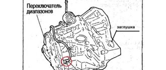
Signs and causes of DS problems
VAZ “tens” are equipped with pointer indicating devices, i.e. the speed is judged by the angle of its deflection. If, while driving, the speedometer needle jumps and jumps, lies at “zero” or shows values that do not correspond to the true ones, and the odometer does not record the distance traveled, then this indicates a breakdown of the DS.
This situation occurs due to contamination of the sensor contact block, since the primary device is located on the gearbox housing under the hood and is not protected from dirt. The pad may be exposed to oil vapors penetrating through damaged seals. This leads to loss of contact and, as a result, incorrect speedometer readings. Such a breakdown can occur both with sensors with a square connector and with a round one. The difference between them is that the former are used in Bosh systems, and the latter in January 4 and GM.
When the speed sensor fails, unstable engine idling is often observed, and fuel consumption also increases. In this case, the DS is replaced. When choosing a working sensor, it is advisable to choose a model that is identical to the old one. Preference is given to products whose pinouts are indicated in the form of “-”, “A” and “+” rather than a digital designation. This will help when repairing the device and measuring the output signal.
The DS drive rod must be metal, not plastic. Otherwise, the service life will be no more than six months. When purchasing a working device, check that it is complete, that there are no backlashes, and that there is a washer on the rod. Replacing the DS is carried out independently and does not cause any difficulties.
VAZ-2110 tachometer connection diagram
- tachometer VAZ;
- trip computer;
- ECM;
- crankshaft position sensor;
- ignition module.
Tachometer VAZ 2110 - with four outputs: if it is on a car with injection, it is connected not to the ignition (input 2), but to the ECM controller with an additional output provided for this (input 1) - and in this case it reads the number of revolution pulses directly from the controller. It receives a signal about the position of the shaft.
About the DPKV tachometer sensor
The tachometer has a sensor (crankshaft position sensor - DPKV). This device serves not only to count crankshaft revolutions, but also to determine its position at a certain moment, which is necessary for the electronic control unit to ensure proper operation of the power unit. When a metal object passes near the sensor core, an electrical impulse is generated in it, which is transmitted to the electronic engine control unit. The role of such an object in the power unit of a car is played by the crankshaft gear.
Device
The tachometer makes it possible to switch to another speed in time so that the engine operates in economical mode. A novice driver can focus on the position of the arrow. If it approaches the red zone, then you need to shift to a higher gear. In addition, the device is used to adjust the operation of the power unit at idle and control the crankshaft speed while driving (author of the video - Avto-Blogger.ru).
Analog tachometers are reliable and simple measuring instruments.
Their design includes the following elements:
- pointer arrow;
- graduated scale;
- an electromagnetic coil with a shielded winding;
- cable for transmitting information from the crankshaft.
The operation of the device is based on the electronic principle. The signal from the crankshaft is transmitted through wires to a microcircuit, thanks to which the needle moves along the dial. Information can be taken directly from the shaft, from the generator or from other power take-off shafts. In this case, the original signal is converted with a certain coefficient.
Why does the VAZ tachometer jump?
It often happens that the needle starts to twitch. If the car is fuel-injected, then troubleshooting involves connecting a diagnostic scanner and checking the engine systems. Jumps in the TX-193 needle in most cases are also a symptom of malfunctions associated with its electrical circuit. The reasons for this behavior of the device may be:
- lack of good contact at the negative terminal of the battery;
- oxidation or burning of the brown wire on the ignition coil;
- burning or wear of the contacts of the ignition distributor cap or slider;
- wear of the distributor shaft bearing;
- shorting the red wire powering the device to vehicle ground;
- malfunction of the crankshaft position sensor (for injection engines).
A similar problem is solved by stripping the contacts, replacing the ignition distributor cap, slider, support bearing, restoring the integrity of the insulation of the device’s supply wire, and replacing the crankshaft sensor.
Another jump may be due to the inoperability of the capacitor located at the bottom of the breaker. The capacitor may be broken or its contact is very weak.
Causes of malfunction
So, basically the malfunction appears due to disassembling the instrument cluster. On many forums, car owners complain that after disassembling the panel, this defect appeared.
But this may not be the only reason. Let's consider the main ones:
- The tachometer control motor burned out.
- The tachometer controller has failed.
- Error in the electronic control unit.
- Part of the instrument cluster board was burnt.
Thus, the main problems have been found.
Disassembling the dashboard
Treatment methods
In order for the tachometer needle to return to its place, it is necessary to eliminate the causes of this effect. So, let's look at how to treat various malfunctions with your own hands:
- The motor burned out. It is necessary to unscrew the panel and unsolder the element contacts. Check the resistance, which should be 300 ohms. If necessary, clean the contacts and solder the motor back. If this does not work and there is no resistance, then you need to install a new motor.
- Tachometer controller. If the motor is sealed and the tachometer does not return, then you need to find the control controller and check it. Replace if necessary.
Now we know how to eliminate the causes of the malfunction.
If the tachometer on a VAZ does not work
Usually, the lack of response from the arrow is due to a broken contact in the connectors of the main wires of its connection, or damage to the wiring of the circuit. The first step is:
- Inspect the fastening of the conductor in brown insulation to terminal “K” on the ignition coil. If you detect poor contact, traces of oxidation, burning of a wire or terminal, fix the problem by cleaning the problem areas, treating them with anti-corrosion liquid, and tightening the fastening nut.
- Check the reliability of the connection of the black and white wire to the vehicle ground. If contact is broken, clean the wire and the surface to which it is attached.
- Using a tester, determine whether voltage is supplied to the red wire when the ignition is on. If there is no voltage, check the serviceability of fuse F-9, which is responsible for the integrity of the instrument panel circuit, as well as the condition of the ignition switch contacts.
- Disassemble the instrument panel and check the connections of the contacts in the tachometer wiring harness block. “Ring” all the wires going to the device with a tester.
Examination
It is better to test the component components of the engine speed counting system in order of priority. This will help to quickly identify the malfunction and conduct an additional examination of the condition of each element.
Before checking the electrical circuit and its parts, you should make sure that the fuel injection system is working. The serviceability of the gas distribution mechanism also affects the performance of the tachometer. Only after checking these components can we assume that the tachometer circuit is not working.
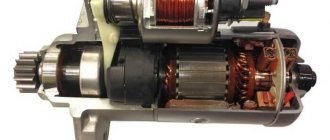
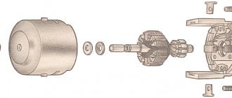
DPKV
This device is located near the machine's generator pulley. You can check its operation using a multimeter. To do this you need:
- Set the multimeter to resistance measurement mode.
- Disconnect the sensor power supply connector.
- Connect the red control probe of the tester to terminal “1”.
- Connect the black measuring probe to terminal “2”.
- Crank the engine with the starter.
When open, the device will show a resistance of up to 550–750 Ohms. If the tester does not measure the operating resistance of the sensor, you will have to dismantle it. To do this, you will need to unscrew one nut that secures the element. Very often, metal shavings stick to the magnetic sensor and interfere with the opening. If chips have accumulated on the rod, they must be removed, the body must be cleaned with a solvent and the resistance measurement must be repeated.
After checking the DPKV, you need to check the integrity of the wiring that powers the sensor and transmits pulse signals to the control unit. It is necessary to inspect the wires and check the integrity of the insulation. You will also have to clean both halves of the connecting plug with solvent.
Ignition module
This device is most often prone to breakdowns. This happens due to a short circuit to ground. The check is carried out with the engine running. During operation of the power unit, it is necessary to remove the power wires from the spark plugs one by one. After this, you need to direct the end of each wire towards the engine block, but without touching it. A spark should appear from the end of each wire. It should be blue. If the spark is yellow or there is no spark at all, the module and wires will have to be ringed.
The wires can be tested with a multimeter only to check the integrity of the cores. It is not possible to determine an insulation breakdown in this way. It is better to replace all suspicious elements with new ones. Often, owners replace standard high-voltage wires with modern silicone analogues; this should not be done. The electrical resistance of such wires is very high; it does not allow the spark of the required discharge to pass through. It is also worth carefully inspecting the caps that are placed on the candles. Parts with poor contact or external defects must be replaced.
Before checking the module, you need to test the wiring that powers this device. To do this, you need to disconnect the plug. Next, you will need a multimeter in DC voltage measurement mode.
- Connect the red measuring probe to terminal “1”.
- Connect the black measuring probe to terminal “3”.
- Turn on the ignition.
The tester should show a voltage of 12 volts or equal to the battery voltage. If there is no voltage at all, then you need to check the integrity of the fuse responsible for the ignition module. It is located under the trim on the right side under the instrument panel, the very first one on the hood side. Has a rating of 15 amps.
If voltage is supplied to the module, then it is necessary to check each coil of this assembly.
- The primary windings are checked for the presence of operating resistance. To do this, you need to switch the multimeter to resistance measurement mode. Next, you need to connect the red test lead to pin 1 of the power wire going to the first cylinder, and the black test lead to pin 4 of the cylinder. The operating resistance must be at least 0.5 Ohm.
- The second primary winding is checked in the same way, only at terminals 2 and 3.
Next, the secondary winding is checked. To do this you need:
- Connect the red measuring probe to terminal “1” on the module socket.
- Connect the black measuring probe to terminal “3”.
- The operating resistance should be 0.5 Ohm.
The third check is the most important. It is carried out to test for the presence of a short circuit.
- The red test probe is connected to the module's connecting socket.
- The black test probe is connected to the device body.
- A working module should not show resistance. If it is, even the most minimal, then the device will have to be replaced.
If the module has fully passed the test, it must be inspected. Any cracks in the housing, even the most minor ones, can create a ground fault during operation in wet weather. Such deformations cannot be eliminated; the unit will have to be replaced with a similar one. You also need to clean the sockets of the high-voltage wires going to the spark plugs.
Fuse
Very often the tachometer does not work due to a fuse problem. If the instrument panel does not work at all and there is no backlight, then we can assume that fuse “F9” has failed. It must be removed and checked using a tester. The multimeter is switched to continuity mode, both test leads are connected to the fuse contacts. The absence of a buzzer will indicate a malfunction of the protective element. It will have to be replaced with a similar device rated 10 amps.
You also need to check the fuse socket. Clean any dirt, oxidation, carbon deposits with alcohol. Bend the contacts with a screwdriver.
Next, the electrical voltage coming to the fuse is checked. This requires:
- Switch the multimeter to voltmeter mode to measure DC voltage.
- Connect the red test lead to the fuse output.
- Connect the black test lead to ground.
- Turn on the ignition.
The voltmeter should show a voltage identical to the battery charge.
Receiver block
If the previously described checks did not bring results, and all the elements are in good order, then you need to test the tachometer itself. A simple check is to reset the odometer. After resetting, you need to hold down the odometer button and turn on the ignition. The tachometer and speedometer needles should deviate to the maximum position and return back. If the tachometer does not respond to the voltage supply, you will have to dismantle the dashboard and remove the device. To do this, you need to unscrew the 4 screws of the cladding in front of the protective glass and dismantle it. Next, remove 4 more screws holding the instrument panel itself. After dismantling, you need to pull the block towards you.
Electrical power is supplied to the tachometer through a yellow (sometimes white) connector. “+” terminal number “8” is the very first in the bottom row. To check the power supply, you must:
- Switch the tester to DC voltage measurement mode.
- Disconnect the plug.
- Connect the red probe to pin “8” of the incoming power cable.
- Connect the black probe to ground.
With the ignition on, the voltmeter should show a voltage of up to 12 volts. If there are no readings, then you should check the ignition switch terminal.
Next, terminal “2” of the receiver unit itself is checked. She is the very first one in the top row. Responsible for power supply with pulsed current. To check it, you need to run a test wire from the “+” terminal of the battery. The second end of the wire must be abruptly connected to terminal “2” several times. The tachometer needle should respond to the simulated impulses by deflecting at a certain angle. If there is no deviation, then the reason lies in the receiver itself.
It needs to be inspected visually for oxidation and broken tracks. A big problem with such receivers is microcracks in the solder. You should carefully inspect all connections and eliminate any defects found. Then repeat the check again.
If the receiver unit is working properly, power is supplied from the ignition and there is a reaction from the arrow to simulated pulses, then the problem lies in the ground terminal. It is the very first one, located in the corner between the rows of plugs. Necessary:
- Set the tester to voltmeter mode.
- Connect the red test probe to terminal “2” of the incoming cable plug.
- Connect the black probe to terminal “1” of the same plug.
- Turn on the ignition.
If there are no readings, then it is worth connecting the black control probe to ground in another place. The presence of data will indicate a break in the ground line. It can be pulled through using a jumper and pre-fixed with a bolted connection in the engine compartment.