Benefits of using HBO
First, let's look at the advantages of installing fourth-generation gas equipment, and there are several of them, but they are important:
- Cost of gas (significantly less than gasoline);
- Consumption (in new generations of gas equipment, gas consumption is slightly higher than gasoline consumption);
- The gas contains no unnecessary impurities (which can be found in gasoline);
- Less deposition of combustion products inside the combustion chambers (affects the life of the power plant);
- When the car is fully refueled (with both gasoline and gas), the range will significantly increase.
With such a significant number of positive qualities, there is also a negative.
HBO 2nd generation for carburetor
Most people do not know what HBO is and what its functions are. In this article you can learn about the principle of its operation, as well as how to correct problems with this equipment.
HBO 2 for a carburetor engine
LPG is a vehicle's gas equipment. There are two types of engines - carburetor and injection. They are different from each other. The first one sucks in gasoline and air using pressure. In this case, remote control is either very low or absent altogether.
And the injector allows you to inject gasoline into the engine using nozzles. All processes are controlled using an on-board computer. Using pressure sensors, as well as oxygen and temperature beams, it obtains information.
Disadvantages of using HBO
The first and noticeable disadvantage of the 4th generation HBO is the cost of the equipment; the higher the generation, the more expensive it is.
But even in this negative there is a positive quality of the equipment - it is universal, so by purchasing it, you can remove and install the equipment on different cars.
The second negative is the cost of installation, if you are sure that it will not be possible to install it yourself, as well as the quality of installation of the equipment.
And the third negative can be considered the advisability of using gas equipment in a car.
Since the equipment is not cheap, if the car is used rarely and for short trips, then installing an LPG will not pay off soon.
Selecting a HBO kit
The kits from these brands contain all the necessary elements. Starting from gearboxes, injectors, valves and ending with special electronic modules that do not require programming or additional configuration.
Model gas equipment of a car is a system unified for a specific make/model of car or platform on which the car is assembled.
Such systems are equipped with all the necessary fasteners, which are unified by seating and designed to distribute the main components in safe places in the car.
The electronic part of the model equipment is pre-calibrated at the factory for a specific car model, and this greatly simplifies the setup and pairing of the gas equipment with the standard ECU system.
Often, when installing a certified model LPG in specialized services, the car does not fall out of warranty service. This point is only valid if gas equipment is installed in special services that provide a guarantee and cooperate with dealer centers.
Branded model LPG has a number of advantages and disadvantages.
Advantages of model gas equipment:
- does not require drilling a large number of holes and installing additional clamps and fasteners, model kits fit “in place” and are perfectly installed in the places provided by the manufacturer;
- does not require intervention in the vehicle’s electronic control unit;
- reliability;
- maintaining the dealer warranty (only when contacting specialized services).
Disadvantages of model gas equipment:
- high price;
- lack of choice (only a limited list of brands and modifications);
- large financial costs for installation in a specialized service.
If a car enthusiast does not have the desire or money to spend on purchasing branded LPG, then you can go the other way and choose a universal set of equipment. Such universal kits are presented in abundance in the assortments of many automobile stores.
One of the main advantages of a unified gas equipment is the ability to select individual elements. Starting from nozzles and gearboxes to special valves and filling containers.
The ability to select and purchase parts separately makes standardized sets of gas equipment very attractive for purchase. As a rule, installing an LPG with your own hands, assembled from various components, does not cause serious difficulties, but requires knowledge of certain skills.
Unified gas equipment kits vary in their characteristics (power, number of cylinders, type of fuel injection, presence of a turbocharger, etc.).
The limiting factors in this case will be only the engine power and the filling tank . The power of the engine will determine which gearbox and injectors will need to be installed, and the location of the filling tank is different on all cars, so this point is worth taking into account.
Advantages of universal gas systems:
- low cost;
- wide availability;
- compatible with a large number of brands and models of cars;
- possibility of individual selection of components for specific operating conditions of the machine.
Disadvantages of universal gas systems:
- there is a risk of running into a defect or counterfeit;
- requires additional work on installation and preparation of attachments;
- deprivation of the dealer warranty (if the car is under factory warranty and the installation is not carried out by a certified service center);
- requires adjustment of the electronic control unit.
List of required tools and equipment
Installing a 4th generation gas system with your own hands is not a difficult task. Before you carry out installation yourself, you need to acquire a certain set of tools.
No specialized tools are required to carry out work related to the gas system. have :
- standard set of socket bits and sockets;
- pliers;
- WD-40;
- electric drill;
- a set of metal drills;
- thread tap (for injector threads);
- sealant and thread locker;
- a set of screwdrivers (including torx screwdrivers);
- torque wrench (optional);
- spare bolts, nuts and washers (preferably).
Installation process
For car enthusiasts who have ever carried out repairs and maintenance of VAZ-made cars with their own hands, the installation of equipment will not cause great demands.
The main thing is to follow all prescribed instructions and check the reliability of the connections made. There is no specific algorithm for installing a gas system on a car; you can start either by inserting the injectors or by securing the cylinder in the passenger compartment or trunk.
The stages of work can be divided into:
- design (fitting connections, planning the placement of parts);
- rough installation (drilling holes, laying lines);
- gearbox installation;
- injector insertion;
- securing the cylinder;
- final installation (connecting all elements together, securely tightening nuts and bolts, checking for leaks);
- electronic pairing and setup
Injection insertion and ramp installation
Let's start with the most difficult part, with inserting the injectors into the intake manifold. To do this, you will need to disconnect the air filter, electronic chips from the throttle and other elements attached to the intake tract. To remove the collector itself, you need to unscrew the fixing studs (less commonly, bolts) and carefully pull the collector off the studs.
Once the manifold is removed, it is necessary to mark the holes for inserting the gas injectors. The distance from the adjacent plane of the cylinder head manifold to the insertion point can vary in the range from 1 to 7 cm.
We select a place for insertion with the largest diameter so as not to interfere with the normal air flow. Once the location for the injectors has been selected, the areas on the manifold that will need to be drilled should be marked.
The holes for the injectors must be drilled at an angle of 45-90 degrees in the direction of the air flowing into the engine. You should work with a drill at low speeds, and it is better to start with a small drill, and towards the end of drilling, replace the drill with a suitable diameter and drill the holes to the end
After drilling the holes for the gas injectors, take a tap and cut the thread. Now we thoroughly clean the intake manifold and install the injectors. Before inserting, it is advisable to use a thread locker and secure the nozzles to a locklight or clamp.
Features of HBO of different generations
So, it was decided to install HBO on the car. First you need to figure out which generation of equipment is best to use. It all depends on the car itself.
If a car uses a carburetor power system, then there is no particular choice - only 1st and 2nd generation gas equipment is installed on such cars.
Of course, there are craftsmen who install more modern equipment on such cars, but this is labor-intensive and expensive.
On injection cars you can install 2, 3 and 4 generations of gas equipment. Let's go through them.
HBO 2nd generation.
It is simpler in design, has mechanical control and adjustment.
This makes it possible to use it on many cars with both old and new injection power systems.
But this equipment has such a drawback as the lack of clarity in the dosage of gas supply, which often leads to its overconsumption.
HBO 3rd generation.
Already has a mechanism for precise dosing of gas supply. But the execution of the serve leaves much to be desired.
Equipment that is used as an alternative to the gasoline power system is significantly delayed in determining the amount of gas required at a certain moment in the operation of the power plant.
This drawback ensured a “short life” for equipment of this generation; it is now rare, and the feasibility of its use is a big question.
HBO 4 generations.
The most advanced equipment at the moment for use on modern injection cars.
And although gas equipment of the fifth and sixth generations already exists, at this time gas equipment of the fourth generation is the most popular and widespread.
Connected to the standard power system and using signals from the standard car power system control unit, the equipment performs a very precise dosage of the amount of gas required at a certain moment for optimal operation of the power plant.
Nuances of purchasing 4th generation HBO
Let’s focus specifically on the 4th generation gas installation, and we will consider the sequence of installing it on a modern injection engine.
The basis will be an ordinary modern injection car with 4 cylinders and average power, since installing this equipment on a car with a large number of cylinders, or with increased power indicators has its own characteristics.
This choice is due to the massive use of cars with exactly these indicators, regardless of the brand.
We decide on the choice.
First you need to decide on the purchase of this equipment. All pieces of equipment can be purchased as a set, or individually. This has its positive qualities, as well as disadvantages.
Purchasing equipment as a set from a branded manufacturer will ensure high reliability of all elements, since they undergo quality certification.
And the installation of equipment will be easier, since the connecting elements and debugging of the equipment have already been completed. But purchasing the kit will cost much more.
By purchasing pieces of equipment separately, you can save a lot.
Many elements are common to all types of gas equipment, and their cost individually will be lower than in the kit.
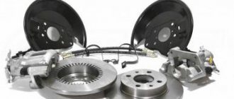
But some elements of equipment are used only on installations of this generation. This includes a gas reducer, used only on the 4th generation of gas equipment, a gas train with electromagnetic injectors, an electronic control unit, and the sensors required for the operation of this equipment - gas temperature and pressure.
You need to purchase this equipment with a serious approach; it is better to overpay a little for high-quality equipment than to be disappointed in the future by the unreliability of its operation.
Having all the elements in hand, either as a kit or as an assembly, you can begin installation.
Of course, you can leave all this work to specialists, but you will have to pay. Or you can do everything yourself, which is cheaper and will give you the opportunity to fully understand how the equipment works.
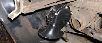
Gas pipeline wiring
Gas pipeline wiring - what it looks like
After installing the cylinder, a gas pipeline is installed from the tank to the engine compartment. For safety reasons, the pipeline is laid outside the car.
The diameter of the hole in the container is taken to be 1-2 mm larger than the diameter of the pipe. The difference in diameter is compensated by inserting a piece of plastic pipe. The resulting gap serves for additional ventilation of the multivalve. The edges of the hole are treated with anti-corrosion mastic.
The gas pipeline wiring is placed in the niche of the fuel line. The pipe is fixed in a constant position using steel clamps. After installing the pipe, begin installing the mixer and valve.
Installation of cylinder, filling device, lines
Let's start with something simple - installing elements common to all gas equipment. Let's start with the balloon. Its installation location depends on the design features of the car.
If the car has a sedan body and there is a trunk of significant volume, then it is more advisable to use a cylindrical cylinder. Its capacity is greater; it is usually attached to the rear wall of the trunk.
If the car is a hatchback, it does not have much luggage compartment, so it is more advisable to install a toroidal cylinder in the place reserved for the spare wheel, if, of course, there is one.
The cylinder must be securely fastened. For this purpose, tapes with fasteners at the ends are used. It is desirable that these tapes have a rubberized surface.
To properly fasten the cylinder, you need to take measurements of where you will need to make holes in the body.
You will also need to mark the places where the high pressure line will exit from the cylinder. After which you will need to make holes in the body in the marked places.
After this, the holes will need to be treated with anti-corrosion treatment.
To further prevent damage to the line from the sharp edge of the hole, you can insert pieces of plastic pipe into it, through which you can then pass the line.
Although the toroidal cylinder fits into the seat of the spare wheel, it also needs to be secured to prevent it from moving.
Fastening is also done with tapes with preliminary preparation of the exit site for the highways.
In both cases of installing the cylinder, they should be installed so that the multivalve installed on it is located in the upper part of the cylinder, and there is easy access to the gas shut-off valve.
Next you need to install the filling device. The choice of its installation is extensive; it is only important to take into account that this place should not become heavily polluted during the operation of the car.
The device can be installed on the rear fender, in the body of the bumper, or under the bumper.
The main thing is to ensure that the line from the device to the cylinder is laid where it will not interfere and there will be no possibility of damaging it.
Let's move on to the highways.
The line consists of brass tubes that must run under the car and go into the engine compartment.
To prevent damage to the lines, it is better to attach them to gasoline pipelines, because they are installed where there is no possibility of their breakdown.
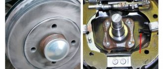
How to install a gas cylinder
When installing gas equipment on your own, two types of cylinders are used:
HBO equipment
- cylindrical cylinders;
- toroidal cylinders.
Cylindrical cylinders have an oblong shape. To protect against gas leakage, they are equipped with a shut-off valve. Used in cars with a spacious trunk and on trucks.
Toroidal cylinders have a “tablet” shape. Used in cars with a small trunk.
The cylinder is mounted in the free space of the body. To protect against displacement, they are secured with steel strips. The ends of the strips are connected with bolts.
After mounting and securing the cylinder, the end of the filling valve is brought out. The end of the hose with a fitting is secured under the rear bumper or under the rear fender.
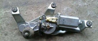
Features of gearbox installation
After running the lines into the engine compartment, they need to be routed along the left side to the gearbox installation site.
The gearbox must be properly secured to the car so that there are no problems in the future.
It is attached only to the load-bearing part of the car, that is, to the body or subframe. It is prohibited to install it on the engine. It is important that there is good access to it.
The gearbox is then connected to the cooling system of the power plant. To do this, it is inserted into the cooling system pipes through tees.
It is important that its insertion is parallel, that is, the flow of coolant into the gearbox should be made from one pipe, and its outlet through another, and not the same one.
Next, a vacuum pipe is connected to the gearbox. Vacuum is taken from the intake manifold.
A fitting cuts into it, and it is connected to the gearbox by a pipeline. If there is no fitting, you can wait to insert it for now.
After this, you can connect the high pressure line to the reducer. Only before this, a filter is included in the design to capture mechanical impurities - a “coarse” filter.
What is needed for proper installation
To properly install gas equipment on a car, you will need a certain set of equipment and tools:
- HBO set 4;
- gas hoses with clamps 60-80cm long, Ø4-5mm and Ø12mm 50-100cm (for a 4-cylinder engine); 40-70cm vacuum tube Ø6mm; a cooling system hose with two metal tees corresponding to the size of the inlet/outlet on the gearbox - the length of all lines is selected individually for the car;
- thermoplastic gas tube of the required length (you can use copper or aluminum);
- auto tools;
- drill and/or screwdriver;
- drills (Ø4.8mm, crown 30mm);
- tap 6mm;
- electrical tape, heat shrink tube, hair dryer;
- soldering iron (materials for soldering wiring);
- multimeter;
- metal clamps/brackets with self-tapping screws (for fastening lines under the bottom);
- a can of anti-corrosion treatment or auto enamel;
- engine intake manifold gasket.
You will also need a lift/overpass or inspection hole.
Gas train
Leaving the gearbox for now, we move on to the intake manifold. It will be necessary to insert gas fittings into it.
Since you will have to drill holes in the manifold, in order to prevent chips from getting into the valve mechanism, it is better to insert the fittings on the removed manifold.
You can, of course, make holes on the manifold mounted on the engine, but then you need to drill carefully to minimize the entry of chips.
We will assume that the manifold has been removed and can be drilled.
The holes for the gas supply fittings should be made as close as possible to the gasoline injectors, but at the same time take into account the position of these injectors so that they do not interfere with the installation of gas supply pipelines in the future.
Below are several options.
At the same time, a hole is drilled for the vacuum supply fitting to the gearbox.
The holes must be smaller in size than the diameter of the fittings. Then you need to cut threads in the holes.
Before screwing in the fittings, their threads must be lubricated with sealant.
After this, the collector is installed in place and further installation of equipment continues.
Next in the connection diagram is the installation of a ramp with electromagnetic injectors.
The ramp is installed at the top of the collector, but so that it does not interfere with pipelines and wiring.
Pipelines are laid from the ramp to the installed gas supply fittings. It is important to ensure that the length of the pipelines running from the ramp to the fittings must be the same, otherwise there will be a malfunction of the system.
Having installed the ramp, you need to lay a gas supply pipeline from the reducer to it. At the same time, another filter is inserted into the pipeline - fine gas purification.
Again, we return to the gearbox and connect the vacuum supply pipeline to it. All pipelines must be covered with clamps to prevent gas leakage at the joints.
This completes the technical part of the installation of gas equipment, let's move on to connecting the electronic part.
Self-installation of gas equipment
Second-generation equipment has become most widespread. It is characterized by simplicity of design and installation. Distinctive advantages allow you to install LPG on a car yourself.
Connection diagram for gas equipment
System installation work is carried out in the following order:
- Installation of the cylinder.
- Installation of shut-off valves.
- Fastening of mixers and valves.
- Installation of dispenser and gearbox.
- Fixing the control panel.
- Checking the tightness and operation of the system.
Installation of the HBO control unit
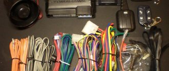
The operation of the equipment is controlled by an electronic control unit, which comes with the 4th generation gas equipment.
Wiring to the control unit.
First you need to decide on the location of the block. Access to it should be free, but at the same time it is necessary to minimize the length of the wiring so that after connecting it, a heap of tangled wires does not form under the hood.
All wiring coming from the controller is divided into several parts, each of which performs its own functions.
The main thing is to have on hand a diagram with a color definition of which part this or that wire belongs to. Or at least this one.
Before connecting the wiring, you need to disconnect the on-board network from the battery.
First, you need to determine which wires are responsible for powering the unit. There should be three of them - to the positive terminal, to ground, and to the positive terminal of the ignition switch. Having separated them, it is better to immediately connect.
Wiring to injectors.
Next, we move on to the wiring responsible for the operation of the injectors - the fuel part. This wiring is connected to the wires going to the gasoline injectors.
After determining which wires are connected to each specific injector, they are inserted.
The color scheme determines which wire needs to be connected to which one, then the connection is made.
You can use conventional twisting followed by insulation, but such a connection is not reliable; it is still better to solder the wires from the control unit at the connection points and then insulate them.
For the fuel part of the wiring, all that remains is to connect the connectors back to the gasoline injectors, and also connect the connectors of the electromagnetic gas injectors.
The fuel part of the wiring is finished, let's move on to the next one.
Signal wiring.
Let's move on to connecting the next part of the wiring - the signal one.
This wiring is designed to transmit signals from sensors that come with the equipment - gas temperature and pressure.
The accompanying instructions indicate in which places the sensors should be placed. After installing the sensors, wiring from the control unit is connected to them.
Wiring for the operating mode switching unit.
The last part is the control of the operation of the control unit, that is, the unit for switching the operation of gas equipment.
The control unit is installed in the cabin, in a place accessible for viewing and control.
After which it is wired and connected.
It is advisable to collect all wires into bundles and secure them to prevent the possibility of accidental damage.
The control unit has one more output for connecting a computer, which regulates the operation of the equipment.
This outlet must be freely accessible to facilitate adjustment and diagnostic work.
At this point, the work on installing 4th generation gas equipment on the car is completed.
But what remains is checking the tightness of the system, and then checking and adjusting the operation of the equipment.
Installation and connection of HBO 4: features
Let us immediately note that the material below is not an instruction and is more related to informational information. Please note that without the proper experience and skills, it is better to avoid installing gas equipment with your own hands.
In other words, it is not enough to know how to install gas on a car, since in addition to successful installation, you will also need LPG settings. For this reason, self-installation, which is usually carried out for training purposes, must always be supervised and completed by a qualified technician.
- So, after selecting and preparing a set of gas equipment, the first thing you need to understand is what the position of the gearbox will be. By the way, the device of the HBO 4 gearbox in a simplified form assumes the presence of two chambers. Liquefied gas enters one chamber under high pressure, after which it evaporates and passes into another chamber, where the pressure decreases. Next, the gas from the reducer flows to the engine. Gearboxes can be vacuum or electronic, with the second type being more modern and actively replacing the first.
The gearbox itself is quite massive, hoses are connected to it, so it is necessary to determine in advance the location of its installation in the engine compartment. At the same time, free access must be maintained, which is necessary for removing and servicing the gearbox (replacing filters). In practice, the gearbox must be mounted away from the internal combustion engine and on the load-bearing elements of the car body, and not on the engine, in order to prevent excessive heating, vibration, etc.
It is also necessary to take into account that the coolant supply hoses must be supplied without kinks, twisting or bending when laying them. The coolant should circulate freely in the hose.
Separately, it is necessary to determine the location for the main gas supply line. The line can be copper or plastic; it is also important to prevent the tube from becoming bent, chafed or damaged during further operation of the vehicle; if necessary, remove the gearbox, etc.
Having installed (embedded) the gearbox, you can proceed to connecting the coolant hoses. The hoses must always be connected in parallel. Usually the connection is made to the coolant inlet and outlet of the heater radiator. If the radiator is difficult to access, other places are used for insertion, and it is important to know where the coolant supply and the so-called “return” will be. Errors can lead to problems in the operation of the gearbox and cooling system of the car.
You also need to consider how the shut-off valve is located. On some cars, the valve comes first, and then the hose is connected to the supply to the heater radiator. In this case, you need to connect to the shut-off valve by inserting a tee. The connection should be made only through tees, and not through an angle connection.
The tee will allow for a parallel connection, that is, the radiator and the gearbox will have the same coolant supply. As a result, both the gearbox and the car interior will warm up well. In fact, this is the answer to the question of how the gearbox is installed on different gas equipment, that is, the gas reducer is installed (Lovato 4th generation, BRC, etc.).
If you make a serial connection, in this case the last element will receive cooled coolant. In this case, the gearbox and HBO will not work correctly in winter, when the heat from the antifreeze will be absorbed by the heater radiator. In the summer, when the stove is not used, the system will work normally.
- Having installed and connected the reducer, you next need to start placing the gas cylinder. If the cylinder is placed in place of the spare wheel, then it must be positioned so that it is possible to connect the supply and filling pipes. It is important to make sure that the tubes will pass normally under the cylinder, that there will be no hot muffler in the place where they pass, and that there are no moving or vibrating elements near the tubes.
Next, the cylinder is bolted to the place under the spare wheel, after which a hole is drilled in the bottom, symmetrical to the hole in the cylinder. If you look at the cylinder from above, you should see a hole in the bottom below. The hole in the body needs to be painted over, treated against corrosion, then a plastic safety fitting is inserted. This will prevent the tube from rubbing against the sharp edges of the hole in the bottom.
Next, a multivalve is placed in the cylinder. Also, the installation sites of the valve and cylinder can be coated with grease or lithol. Then the filling tube is laid to the location of the filling valve. The filling valve can be rigidly fixed in a convenient place; a copper tube is connected to it. The tube is connected to the multivalve and the filling valve; to begin with, the nuts are not tightened too much.
Full tightening is done after laying the gas supply pipe to the reducer. The gas supply pipe from the valve to the gearbox comes from the engine compartment, that is, from the gearbox. The tube is not flexible, it is important to avoid any sharp bends. It is optimal to lay the specified pipe along the bottom parallel to the pipes of the gasoline supply system.
After finishing the tube, wrap the end with electrical tape to prevent dirt from getting inside. The end near the multi-valve is released and an allowance is left. Next, the tube is secured with ties. After securing, you need to place the tube under the hood so that it does not come into contact with moving elements.
Having estimated how the tube will lie up to the gearbox, we cut off the excess, leaving about 40-50 cm of allowance. The allowance is needed for reserve, since the tube is rolled into a ring. This will avoid creases when removing the gearbox and other unexpected tube breakdowns. Now you can connect the tube to the reducer, and the other end to the multivalve.
It is important to avoid any kinks or creases in the tube when connecting, since it is difficult to connect to a multivalve fitting or reducer valve, especially without experience. If there is a bend or crease, the entire line needs to be replaced. It is forbidden to bend the tube after a bend, as this directly affects safety.
By the way, the gas level in the 4th generation LPG cylinder is determined using a sensor. The sensitive element is placed on the multi-valve, and a simple light indication or a more accurate dial indicator, as well as a digital indicator of the gas level in the cylinder, is displayed in the cabin. Next, the sensor is calibrated.
- After the cylinder has been installed, the reducer has been installed, the connection to the cooling system has been made, and the gas filling and supply line has been laid and connected, you can begin installing the gas injectors.
To supply gas to the intake manifold, you need to make taps. You need to cut as close as possible to the gasoline injectors, paying special attention to the angle and direction of the gasoline injector. This is important, because the more correctly the gas is supplied, the better the mixture will burn. The holes are drilled with a smaller drill of 5, then the thread is cut with a tap with a diameter of 6. Before cutting, the hole is lubricated with oil.
Some chips will inevitably end up in the collector, but the amount should be kept to a minimum. Next, the tap fittings are taken and lubricated with liquid to secure the threads. Please note that when drilling holes for taps, you need to take into account the space for the hose (the hose wall is about 4 mm thick). In the future, this will make it more convenient and easy to remove and install the fitting hoses.
The inserts themselves are made of brass, conical and fragile. While tightening, they need to be clamped, but not overtightened. When overtightened, the insert breaks off, the thread will remain in the manifold. Next you can install the injectors. Please note that all hoses from nozzles to fittings should not be more than 18 cm in length and identical in relation to each other.
Having secured hoses that are suitable in diameter (4 or 5), you need to make sure that the hose fits tightly around the fitting. If this is not the case, and also for safety reasons, you should additionally use tie clamps.
- The next stage is electrical. Although at first glance everything seems very complicated without experience, in reality you can figure it out. Often all HBOs have wires of the same color. Also included with the kit are connection instructions, where the colors are indicated.
Let's move on. First you need to decide where the HBO control unit (the so-called brains) will be installed. The installation location must be dry, clean, and not subject to vibration or excessive heat. The block should not make it difficult to access other elements under the hood in case of repairs. It is also important that there is enough wiring when connecting the unit to the gearbox.
Before starting work, remove the terminals from the battery. At the initial stage, you need to lay the power wire to the valve coil (black and blue wire). The laying is carried out along the body. Next, the power cable to the battery is laid. This is a red and black wire with a fuse. Red goes to “plus”, black to “minus”.
Then the remaining wires need to be divided into wiring to the engine, to the gearbox and to the car interior, checking the color instructions. Please note that the wires going to the engine must be carried out with a reserve, making a loop. This is necessary to avoid damage and ruptures when the engine is started, the body begins to oscillate while driving, etc.
The wires for the gasoline injectors are connected to the injector circuit. To do this, you need to remove the connectors from the injectors, put the terminals on the battery and turn on the ignition, after which you need to “ring” the injector chips. On all injectors you must first find the “+”, remembering the location. The wire located next to the chip is exactly what is needed.
Please note that the chip has both a constant “+” and a separate pulse “-”, and you need to find the minus. Next, you need to turn off the ignition and cut the negative wires on the injectors. The signal to the LPG control unit is taken from this wire.
To get a signal, you need to pay attention to the fact that the wiring to the injectors contains both plain and striped wires. The cut wire on the injector also has two ends (one to the injector and the other to the engine ECU). You need to connect like this: a single-color wire from the gas system (for example, yellow) is connected to the wire going to the connector of the injector for gasoline injection. A wire of a similar color, but with a stripe, must be connected to the wire that goes to the car's engine ECU. Other injectors are connected in the same way.
The only thing you need to consider is the order in which the injectors are located (for example, from left to right). The wires for gas are connected in the same order by color (yellow to the first injector, green to the second, etc.). The instructions for the LPG usually indicate which color is suitable for each cylinder (injector connector).
Now you can move on to the wiring that connects to the gas injectors. This wiring has connectors, and they are often numbered. If there are no numbers, then you need to connect according to the color of the wires that connect to the gasoline injectors. The connectors are connected in exactly the same way as the connection to the gasoline connectors was previously made. You also need to check the quality of the connection of gas hoses from the injectors to the inserts in the manifold.
The next step is to connect the PRM speed. For this, a brown wire is usually used, which is connected to the impulse wire to the coil. This connection allows you to read engine speed.
To find the wire, you need to turn on the ignition, then under the hood find the connector that goes to connect the ignition coil. By ringing, it turns out that there are often three wires (plus constant, plus pulse and minus). It is necessary to find the impulse minus. When removing the insulation, we throw on the brown wire of the gas system, after which we apply the insulation.
Now you need a “plus” for the control, which is connected in the place where power is supplied when the ignition is turned on. This is the red wire. It is optimal to take this plus from the plus on the gasoline injector connector. Next we move on to connecting to the gearbox, which is quite simple. The corresponding wires are connected to the terminals on the reducer coil, to the temperature sensor on the reducer (the temperature sensor is screwed into the reducer), to the gas level sensor on the multivalve.
Now the wires of the gas control button, which is responsible for turning the system on and off, are laid. So, when the 4th generation HBO button is connected, the instructions are as follows: you need to find the thickest harness that has a lot of wires. In the car interior, the place where the button will be located is determined. Next, a wire is pulled into the cabin from the engine compartment. Next, all wires are connected by color.
The final step is to connect the MAP sensor wire. This wire has a connector. The MAP sensors themselves are different. The first type is a solution that is installed on the body in a dry place, protected from moisture. The second type of sensors is installed directly into the gas supply hose (from the gas reducer to the gas injectors).
Having decided which type, you need to install the sensor in accordance with the recommendations. As a rule, today the second type is more often used. This MAP sensor has outputs on the body. The wide outlet must be connected into the gap to the hose that goes from the gearbox to the gas injectors. Vacuum tubes are connected to the thin outputs.
Please note that for the MAP sensor you also need to drill a hole in the manifold. The procedure is similar to tapping for injectors, but there are some peculiarities. The insertion location must be selected precisely to prevent mixing of separate gas supply chambers and a common flask. If you look at the manifold, a single bulb is divided into separate sections for each cylinder. The insertion must be made before the separation begins, that is, at the extreme point of the common flask.
If everything is done correctly, all that remains is to connect the wire to the MAP sensor to the sensor itself. The quality of laying of all wires is also checked, the wires are secured with ties. In conclusion, we note that you need to add coolant to the cooling system, avoiding the formation of air pockets.
The final stage after installation will be starting the engine, since the engine needs to be warmed up to set up the LPG. To do this, you need to connect the battery terminals, insert the key into the ignition, but do not start the engine immediately. You need to give the fuel pump time to build up pressure.
Next, as soon as the engine starts to “catch” when trying to start, you need to immediately apply more gas so that the engine starts working normally. If this is not done, the car may not start again for a long time. The fact is that chips that appear during drilling can get under the valve, and compression drops. However, do not worry, small chips will not damage the valve seats.
After the engine starts, you need to warm up the unit and then test the gearbox. Normally it should be hot. If the gearbox is cold, the air plug is removed from the cooling system. To do this, it is often enough to throttle well at XX. After warming up the engine and making sure that everything is working, you can move on to the LPG settings.
Checking the tightness of the system
So, the equipment is installed, you need to check the tightness of the system.
To do this, you need to go to a gas station and “blow out” the full tank. But at the same time, the gas supply valve to the system must be closed.
Then he goes to the viewing hole.
All connections and pipelines of gas equipment up to the gas train must be moistened with a soap solution before opening the supply. If gas passes through, this solution will bubble at the leak site.
The leak test can be done in parts. First, moisten the pipes coming from the cylinder with the solution.
Not only the connections are checked, but also the pipelines themselves, since a leak can occur due to a defect in the pipeline itself or in the event of a breakdown during installation.
After checking the lines going into the engine compartment, you need to check the tightness of the connections of the equipment installed there.
The gas supply to the reducer and the outlet from it to the gas train are checked. There is no need to check further until the equipment is connected to operation.
Connections downstream of the gas train can be checked later.
If the tightness test shows that there is no gas passage, you can proceed to the next step. If a leak is detected, for example, at the junction of pipelines with equipment, then the gas supply is shut off and additional crimping or repacking of the connection is performed. After which a re-check is carried out.
If a leak is found in the pipeline itself, it must be replaced from connection to connection.
Attempting to seal a leak with improvised means practically does not lead to positive results.
After replacing the damaged pipeline, a leak test is carried out again. It is important to ensure that there are no gas leaks anywhere.
How to install a mixer and gasoline valve
The mixer is mounted between the carburetor and the manifold. The joints are sealed with rubber gaskets or silicone sealant. Careful sealing of joints protects cylinder equipment from air entering the system.
Gasoline valve for HBO
The gasoline electric valve is installed from the side where the fuel pipeline connects to the gasoline pump.
Attention! The gasoline electric valve is installed after the gasoline pump. Otherwise, the fuel pump will not be able to supply fuel to the carburetor.
To install the valve, the necessary part of the pipe is cut in the area between the fuel pump and the carburetor. A valve is inserted into the resulting incision. The joints are sealed and clamped with clamps.
Then proceed with the installation of the gas valve. It is installed on the opposite side of the gasoline electric valve. The outlet of the fuel line is connected to the gas valve.
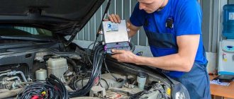
Connecting HBO to PC
Both the cord and the diagnostic program can be purchased. Typically, equipment manufacturers sell them.
After installing the software on the laptop, it is connected to the control unit.
In order for their connection to occur, the control unit must be powered, that is, the ignition switch must be turned on, but the engine must not be started.
If the connection does not occur, the laptop may have an outdated version of software installed, but you also need to check the tightness of the contacts.
If the connection is successful and the program is launched, all the basic information on the engine will be displayed on the laptop monitor - the number of cylinders, types of installed injectors, their polarity, engine speed, current temperature, pressure in the system.
In this case, the system control unit installed in the cabin should light up with warning lights.
One is green, indicating the use of gasoline as fuel, and will glow constantly, the second, red, will flash, signaling the possibility of connecting gas equipment to operation.
In the future, if the equipment is properly configured, signals will be sent to this unit in accordance with certain operating modes.
Possible faults
After installing the equipment or during its use, motorists often need to repair the gas equipment. In most cases, repair work is required due to problems in the operation of the engine when switching to gas or the appearance of pronounced disturbances in the operation of the gas equipment itself. In order to clearly show the main malfunctions of gas equipment to our readers, we present the following list of breakdowns for consideration:
- Unstable operation of the engine on gas or its complete failure. The range of possible problems here is very wide. In principle, absolutely any element of the gas equipment can be faulty. Note that if the latter was installed recently, then to begin with it will be enough just to check the correct installation of all components of the equipment. Otherwise, don’t be too lazy to diagnose the entire gas equipment, purify, adjust and, if necessary, repair the equipment. You may need to purchase a repair kit;
- Problems in the operation of the evaporator gearbox (the car refuses to run on gas or does it extremely poorly, there is instability in idle speed). All you need to do here is to set up the gas equipment correctly, check the tightness of the unit, drain the condensate from it and clean it thoroughly. If these operations do not produce any effect, the situation can be corrected by using a repair kit. Naturally, all faults found must be eliminated;
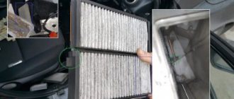
- The LPG filters are clogged and need to be changed every 10,000-20,000 kilometers (symptoms are similar to those that occur with problems with the gearbox). To repair such a malfunction, a repair kit is not required; it is enough to purchase filters and replace them;
- Popping noises appeared in the intake manifold. Here it is important to diagnose HBO using special equipment. In most cases, it helps to identify the presence of a particular problem. By the way, the essence of the claps may lie in both air leaks and incorrect settings of the gas equipment;
- Gas leak (there is a smell in the cabin). In the event of such a breakdown, it is necessary to immediately diagnose the equipment, identify the location of the leak and seal it. It is better to stock up on several repair kits in advance;
- The metering nozzles are clogged or faulty (the engine is unstable at all speeds or refuses to function at all). This problem is always identified through diagnostics and requires either cleaning or replacing the dispensers, nothing else.
In addition to the malfunctions noted above, HBO often suffers from sensor breakdowns, minor depressurization and incorrect settings. Such problems can be eliminated routinely using repair kits or correct adjustment of equipment.
As you can see, installing, repairing and operating gas equipment is not as difficult as it might seem at first glance. The main thing in the process of these procedures is to adhere to the provisions noted above and study in detail the documentation supplied with the equipment. We hope you found today's article helpful. Good luck on the roads!
If you have any questions, leave them in the comments below the article. We or our visitors will be happy to answer them
Auto-configuration of equipment
In this case, you need to press the button for forced operation on gasoline. After this, the red warning light will go out.
To configure the operation of gas equipment, the power plant must be warmed up on gasoline.
After starting the engine, the correct compatibility of the program with the control unit can be checked again by comparing the indicators of the on-board computer with the indicators on the laptop screen, since information about the operation of the engine is displayed there.
After the engine reaches the optimal operating temperature, you can begin auto-calibrating the operation of gas equipment.
This is done by clicking on the window that says “auto-tuning” on the laptop screen.
The essence of this setting comes down to the following. After turning on auto-calibration, the electronic control unit checks the main parameters of the engine - operating temperature, pressure, etc., and, if they correspond to the required parameters for calibration, begins to connect one of the gas injectors to operation.
To do this, he turns off the working injector and connects the gas one; he usually starts doing this from the first cylinder; the connection of the gas injector can be monitored on the laptop monitor.
But when connected, the control unit supplies minimal fuel, which leads to engine vibration, since the control unit has not yet adjusted to the operation of the standard control unit.
Next, the control unit begins to receive information from the standard unit and process it, that is, adapt to its operation; as a result, it adjusts the amount of gas, which is equivalent in energy output to the amount of gasoline. With the correct amount selected, the vibration of the power plant will subside.
Next, the control unit performs the same operation, but with a different nozzle.
Moreover, the control unit for calibration uses the non-sequence of the arrangement of the cylinders, but the order of their operation. If, for example, the operating order is 1-3-2-4, then he will calibrate the injector of the third cylinder next.
Since the sequence of actions of the control unit is identical to the first cylinder, when the gas injector of the third cylinder is connected to operation, the vibration of the power plant will appear again, but it will be weaker.
Next, when calibrating the remaining injectors, you can determine whether the gas equipment was connected completely correctly.
The fact is that after connecting the second gas injector to operation, if installed correctly, the activation of the remaining injectors will not manifest itself in the form of vibration of the power unit, since the supply of gas to two injectors and one gasoline during calibration is sufficient for the engine to operate without vibration.
If vibration persists even after calibrating the second injector, this is a signal that the correct gas supply to one of the electromagnetic injectors has been disrupted.
Problems with operation can be caused either by the difference in the length of the pipes from the ramp to the fittings or by a leaky fitting of the fitting.
The program installed on the laptop will indicate on which cylinder the malfunction occurred. If this malfunction occurs, it must be corrected. Next, auto-calibration is performed again.
Setting up HBO yourself
Let us immediately note that if installing an LPG taking into account the instructions is a complex but feasible task, setting up an LPG assumes that there is a clear understanding of why this or that action is being performed. In other words, for example, setting up a 4th generation Digitronic HBO with your own hands or setting up any other system can rightfully be considered a complex and responsible task.
It is important to understand that errors in settings can lead to unstable operation of the internal combustion engine, various failures, and even failure of the power plant and individual vehicle systems. Please note that if you are not confident in your abilities, it is better to immediately entrust this procedure to an experienced master. If you want to configure the HBO yourself, you will need to buy a special wire (cable) and also install the appropriate software on your laptop.
Please note that the information below is general, that is, it allows you to configure the gas system “on average” so that the engine runs on gas, without the risk of breaking the internal combustion engine or reducing its service life. However, only a specialist can make fine adjustments, which reduces consumption in different modes, increases engine performance on gas, etc.
We also recommend reading the article about whether gas is harmful to a car engine. From this article you will learn about the effect gas has on the engine, as well as how much the engine life is reduced after installing gas equipment, which affects the durability of the engine when running on gas, etc.
By the way, all systems are similar to each other, that is, for example, setting up a 4th generation Lovato LPG with your own hands will not differ much from similar settings in other systems. The only difference is in the graphical interface of the programs themselves and some options that are needed for advanced configuration.
- So, before starting the setup, you need to warm up the car until the engine reaches operating temperatures. Next, you need to remove all load from the internal combustion engine, except for idling (turn off the heater, headlights, dimensions, additional equipment, etc.). Now you can connect with a cable and run the unit setup program. Let's look at the HBO tincture, using the STAG4 program as an example.
First, in the program window, you need to set the number of engine cylinders per coil; the RPM speed must also match the engine speed (550-940). All data must exactly match the vehicle.
After this, you need to go to the tab where the switch-on temperature is set. For summer not lower than +35, and for winter not less than +40. Cylinder shutdown is set to 250. This will allow for a smooth transition from gasoline to gas and back, without engine vibration.
As for pressure error time, this parameter is set at 300 to 420. When choosing the type of gas injectors, it is important that the selected type is exactly the same as those on the machine. If the owner does not know which injectors are installed, the injectors need to be inspected. Manufacturers usually mark them so that the program can then determine which injectors are installed.
The operating pressure of the gearbox should be from 1.0 to 1.3 bar, the minimum is not less than 0.50. Fuel type LPG for propane or CNG for methane (marked). Now you can go to the automatic configuration tab and click start (start). All you have to do is wait from 1 minute to 5 minutes. The setup time depends on how well the car runs on gasoline. If the engine is not running stably, there are problems with the ignition system, etc., then it will take more time for auto-tuning.
Next you need to go to the map tab. There you can see that the orange line has taken a bend. So, it is important to note from which number in the coefficient section the line begins. It is good if the line lies in the range of numbers from 1 to 1.4. The fact is that when installing LPG, a specialist must select the right injectors in terms of performance, taking into account the power of the car’s engine.
The fact is that some injectors can be adjusted to the engine, since they have a performance margin, while others are designed for a specific power and the margin is minimal. In any case, the pressure of the reducer is important for all types of injectors. During auto-tuning, the program itself will calibrate the pressure of the reducer, and the line may become higher than a coefficient from 1 to 1.4 or lower than this indicator.
In the first case, overestimation indicates that the pressure is from 1 to 1.3 bar, but the injector nozzles are too narrow. This suggests that it is possible to increase the performance of the injectors by drilling out the nozzles and making them wider, which will increase the throughput.
If the line is below the coefficient, this indicates large nozzles. In this case, the throughput of the nozzles is reduced by changing the nozzles to suitable analogues with a smaller diameter. Note that the line at a pressure of 1-1.3 should normally be in the range of the coefficient 1-1.4. With such indicators, throttle response is maintained, gas consumption does not exceed 20% compared to gasoline, and the engine operates under normal conditions, there is no big risk of reducing its service life.