As you know, LPG can significantly reduce fuel costs, especially taking into account the constantly rising prices for petroleum products. Today, the most popular and widespread version is HBO 4. According to the rules, the installation of such equipment must be carried out in specialized service centers, which then issue the documents necessary for registering HBO with the State Traffic Inspectorate.
However, many car enthusiasts, for a number of reasons, are interested in how to install 4th generation LPG with their own hands. Also, especially taking into account the tightening of standards and fines for gas equipment without registration, drivers want to know how to remove the 4th generation gas equipment with their own hands, so as not to incur additional costs.
In some cases, owners of gas-powered cars also need to know what the principle of operation of a 4th generation LPG on an injector is, how to adjust a 4th generation LPG yourself, how to turn off the gas on a 4th generation LPG, etc. Next, we will look at the features of installing an LPG 4 on a car, what a gearbox for a 4th generation LPG is and the design of a 4th generation LPG gearbox, how the LPG 4 reducer is installed, and also how to set up such gas-cylinder equipment.
Benefits of using HBO
First, let's look at the advantages of installing fourth-generation gas equipment, and there are several of them, but they are important:
- Cost of gas (significantly less than gasoline);
- Consumption (in new generations of gas equipment, gas consumption is slightly higher than gasoline consumption);
- The gas contains no unnecessary impurities (which can be found in gasoline);
- Less deposition of combustion products inside the combustion chambers (affects the life of the power plant);
- When the car is fully refueled (with both gasoline and gas), the range will significantly increase.
With such a significant number of positive qualities, there is also a negative.
Self-tuning
Before tuning, it is recommended to drive a little on gasoline, this is necessary so that the gasoline brains “feel” the normal mode and correct the correction factors.
All self-tuning can do is accurately determine the timing of gas injection at idle. All other engine modes require manual adjustment. It’s a pity, most often gas workers limit themselves to only this mode.
We connect the cable to the car, turn on the Lovato Easy Fast program, initialization occurs, which takes some time. In the lower right corner the cable icon is displayed with a green check mark. From this moment you can start setting up.
Disadvantages of using HBO
The first and noticeable disadvantage of the 4th generation HBO is the cost of the equipment; the higher the generation, the more expensive it is.
But even in this negative there is a positive quality of the equipment - it is universal, so by purchasing it, you can remove and install the equipment on different cars.
The second negative is the cost of installation, if you are sure that it will not be possible to install it yourself, as well as the quality of installation of the equipment.
And the third negative can be considered the advisability of using gas equipment in a car.
Since the equipment is not cheap, if the car is used rarely and for short trips, then installing an LPG will not pay off soon.
Features of HBO of different generations
So, it was decided to install HBO on the car. First you need to figure out which generation of equipment is best to use. It all depends on the car itself.
If a car uses a carburetor power system, then there is no particular choice - only 1st and 2nd generation gas equipment is installed on such cars.
Of course, there are craftsmen who install more modern equipment on such cars, but this is labor-intensive and expensive.
On injection cars you can install 2, 3 and 4 generations of gas equipment. Let's go through them.
HBO 2nd generation.
It is simpler in design, has mechanical control and adjustment.
This makes it possible to use it on many cars with both old and new injection power systems.
But this equipment has such a drawback as the lack of clarity in the dosage of gas supply, which often leads to its overconsumption.
HBO 3rd generation.
Already has a mechanism for precise dosing of gas supply. But the execution of the serve leaves much to be desired.
Equipment that is used as an alternative to the gasoline power system is significantly delayed in determining the amount of gas required at a certain moment in the operation of the power plant.
This drawback ensured a “short life” for equipment of this generation; it is now rare, and the feasibility of its use is a big question.
HBO 4 generations.
The most advanced equipment at the moment for use on modern injection cars.
And although gas equipment of the fifth and sixth generations already exists, at this time gas equipment of the fourth generation is the most popular and widespread.
Connected to the standard power system and using signals from the standard car power system control unit, the equipment performs a very precise dosage of the amount of gas required at a certain moment for optimal operation of the power plant.
About the Digitronic brand
In 2004, the engineering and management staff of GAZPART 95 began developing the foundation for a new brand. The idea was to use a wide range of high-quality components from various manufacturers. According to the technical specifications of Digitronic specialists, work is being carried out to manufacture equipment at the Italian plant AEB (Alternative Fuel Electronics). However, there are components from other countries. For example, from the Polish company STAG. And this is one of the Digitronic policy lines, in which there are no restrictions in the selection of a high-quality assortment.
In many respects, gas cylinder equipment of this brand can be considered universal, because it can be installed on different car models
It is important that these products are applicable for trucks and passenger vehicles
Nuances of purchasing 4th generation HBO
Let’s focus specifically on the 4th generation gas installation, and we will consider the sequence of installing it on a modern injection engine.
The basis will be an ordinary modern injection car with 4 cylinders and average power, since installing this equipment on a car with a large number of cylinders, or with increased power indicators has its own characteristics.
This choice is due to the massive use of cars with exactly these indicators, regardless of the brand.
We decide on the choice.
First you need to decide on the purchase of this equipment. All pieces of equipment can be purchased as a set, or individually. This has its positive qualities, as well as disadvantages.
Purchasing equipment as a set from a branded manufacturer will ensure high reliability of all elements, since they undergo quality certification.
And the installation of equipment will be easier, since the connecting elements and debugging of the equipment have already been completed. But purchasing the kit will cost much more.
By purchasing pieces of equipment separately, you can save a lot.
Many elements are common to all types of gas equipment, and their cost individually will be lower than in the kit.
But some elements of equipment are used only on installations of this generation. This includes a gas reducer, used only on the 4th generation of gas equipment, a gas train with electromagnetic injectors, an electronic control unit, and the sensors required for the operation of this equipment - gas temperature and pressure.
You need to purchase this equipment with a serious approach; it is better to overpay a little for high-quality equipment than to be disappointed in the future by the unreliability of its operation.
Having all the elements in hand, either as a kit or as an assembly, you can begin installation.
Of course, you can leave all this work to specialists, but you will have to pay. Or you can do everything yourself, which is cheaper and will give you the opportunity to fully understand how the equipment works.
Possible faults
Summarizing the story about the design of LPG injectors, it would not be amiss to pay attention to their possible malfunctions. In fact, there are few of the latter, or rather only three:
- The first option is that the injectors or individual ones have failed. The problem is solved by disassembling, cleaning and, if possible, repairing faulty elements. If this approach does not produce an effect, then you will have to install new nozzles;
- The second option is that there was a malfunction in the injector-control unit system. The malfunction can be eliminated by “dialing” the network and setting up the equipment “newly”. Often, a problem of this nature is solved by contacting an HBO specialist;
- The third option is that the injectors are simply clogged. The easiest way to get rid of this “breakage” is to simply remove the dispensers, disassemble them and clean them thoroughly.
Note that on older generations of gas equipment (up to 3), problems may occur with confrontation between the car’s mono power systems and gas equipment. It seems possible to solve them by introducing an injector emulator into the LPG system (the most preferable copy is from BRC). On most third and all subsequent HBOs, the conflict between mono power systems and equipment is resolved automatically in the control unit, so a similar equipment failure cannot happen with them.
Any malfunction of the injectors is indirectly manifested by the following symptoms:
- instability of the motor;
- loss in power and dynamics;
- inability to switch to gasoline;
- increased fuel consumption;
- failures in engine operation when driving.
Regardless of the nature of the problem with the injectors, they should be eliminated immediately, because using faulty equipment is quite dangerous. Especially when it comes to HBO.
In general, the most important provisions on the issue being considered today have been successfully addressed. We hope the material presented above was useful to you. Good luck on the roads!
Installation of cylinder, filling device, lines
Let's start with something simple - installing elements common to all gas equipment. Let's start with the balloon. Its installation location depends on the design features of the car.
If the car has a sedan body and there is a trunk of significant volume, then it is more advisable to use a cylindrical cylinder. Its capacity is greater; it is usually attached to the rear wall of the trunk.
If the car is a hatchback, it does not have much luggage compartment, so it is more advisable to install a toroidal cylinder in the place reserved for the spare wheel, if, of course, there is one.
The cylinder must be securely fastened. For this purpose, tapes with fasteners at the ends are used. It is desirable that these tapes have a rubberized surface.
To properly fasten the cylinder, you need to take measurements of where you will need to make holes in the body.
You will also need to mark the places where the high pressure line will exit from the cylinder. After which you will need to make holes in the body in the marked places.
After this, the holes will need to be treated with anti-corrosion treatment.
To further prevent damage to the line from the sharp edge of the hole, you can insert pieces of plastic pipe into it, through which you can then pass the line.
Although the toroidal cylinder fits into the seat of the spare wheel, it also needs to be secured to prevent it from moving.
Fastening is also done with tapes with preliminary preparation of the exit site for the highways.
In both cases of installing the cylinder, they should be installed so that the multivalve installed on it is located in the upper part of the cylinder, and there is easy access to the gas shut-off valve.
Next you need to install the filling device. The choice of its installation is extensive; it is only important to take into account that this place should not become heavily polluted during the operation of the car.
The device can be installed on the rear fender, in the body of the bumper, or under the bumper.
The main thing is to ensure that the line from the device to the cylinder is laid where it will not interfere and there will be no possibility of damaging it.
Let's move on to the highways.
The line consists of brass tubes that must run under the car and go into the engine compartment.
To prevent damage to the lines, it is better to attach them to gasoline pipelines, because they are installed where there is no possibility of their breakdown.
Mass air flow sensor device
The internal structure of the sensor is a fine mesh, in the middle of which a platinum thread is stretched. The latter warms up to a temperature of about 700 degrees in a short time. When air passes through it, the thread cools slightly. By how many degrees the filament temperature has dropped in comparison with the reference value, the amount of air passing near it is measured. The output value varies in the range from 0 to 5 Volts. If there is no air flow and the engine is turned off, then the output of the mass flow sensor will be exactly 1 Volt. If you start the engine, air will begin to flow through the mass air flow sensor. The higher its consumption, the greater the voltage will be at the output of the sensor.
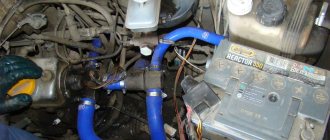
Features of gearbox installation
After running the lines into the engine compartment, they need to be routed along the left side to the gearbox installation site.
The gearbox must be properly secured to the car so that there are no problems in the future.
It is attached only to the load-bearing part of the car, that is, to the body or subframe. It is prohibited to install it on the engine. It is important that there is good access to it.
The gearbox is then connected to the cooling system of the power plant. To do this, it is inserted into the cooling system pipes through tees.
It is important that its insertion is parallel, that is, the flow of coolant into the gearbox should be made from one pipe, and its outlet through another, and not the same one.
Next, a vacuum pipe is connected to the gearbox. Vacuum is taken from the intake manifold.
A fitting cuts into it, and it is connected to the gearbox by a pipeline. If there is no fitting, you can wait to insert it for now.
After this, you can connect the high pressure line to the reducer. Only before this, a filter is included in the design to capture mechanical impurities - a “coarse” filter.
Gas train
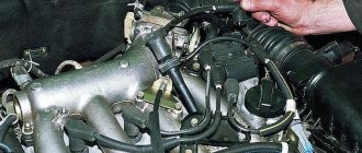
Leaving the gearbox for now, we move on to the intake manifold. It will be necessary to insert gas fittings into it.
Since you will have to drill holes in the manifold, in order to prevent chips from getting into the valve mechanism, it is better to insert the fittings on the removed manifold.
You can, of course, make holes on the manifold mounted on the engine, but then you need to drill carefully to minimize the entry of chips.
We will assume that the manifold has been removed and can be drilled.
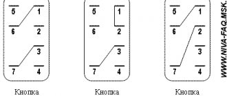
The holes for the gas supply fittings should be made as close as possible to the gasoline injectors, but at the same time take into account the position of these injectors so that they do not interfere with the installation of gas supply pipelines in the future.
Below are several options.
At the same time, a hole is drilled for the vacuum supply fitting to the gearbox.
The holes must be smaller in size than the diameter of the fittings. Then you need to cut threads in the holes.
Before screwing in the fittings, their threads must be lubricated with sealant.
After this, the collector is installed in place and further installation of equipment continues.
Next in the connection diagram is the installation of a ramp with electromagnetic injectors.
The ramp is installed at the top of the collector, but so that it does not interfere with pipelines and wiring.
Pipelines are laid from the ramp to the installed gas supply fittings. It is important to ensure that the length of the pipelines running from the ramp to the fittings must be the same, otherwise there will be a malfunction of the system.
Having installed the ramp, you need to lay a gas supply pipeline from the reducer to it. At the same time, another filter is inserted into the pipeline - fine gas purification.
Again, we return to the gearbox and connect the vacuum supply pipeline to it. All pipelines must be covered with clamps to prevent gas leakage at the joints.
This completes the technical part of the installation of gas equipment, let's move on to connecting the electronic part.
Self-installation of HBO 2
It is not difficult to install gas equipment on a car yourself if you follow safety precautions and have knowledge of installing such devices.
Stages of installation of gas equipment for 2nd generation gas:
- installation of a cylinder;
- gas main wiring;
- installation of a mixer and dispenser and control unit for gas equipment;
- testing work on the tightness and performance of gas equipment.
Before starting installation, check that all gas equipment is available:
- gas cylinder (cylindrical or toroidal);
- multivalve;
- gasoline and gas electric valves;
- filling valve;
- mixer;
- control panel and wires;
- gas hoses and tubes;
- tees;
- clamps.
Description of step-by-step instructions for installing gas equipment:
- Cylindrical cylinders are mounted in trunks. In hatchbacks, a good option for installing a toroidal cylinder is in the spare tire niche. It is better to install methane on large cars, for example, Gazelle, where there is room for a bulky container.
- Fix the filling valve on a bracket under the rear bumper, on one of the rear fenders or in the trunk of the car.
- Lay the gas line from the cylinder to the engine compartment along the bottom of the body. The fuel line must not pass through the passenger compartment. The hole for the gas line outlet is made with a larger diameter than the pipeline in order to insert a protective rubber or plastic seal into it. The edges are treated with anticorrosive.
- A gas line is fixed along the bottom. You can place the gas pipeline next to the gasoline pipeline in the niche provided for this.
- The next step is to install a mixer between the carburetor and the intake manifold of the car. Tightness is achieved using O-rings and sealant to prevent air leaks. If this is not done, traction will be lost and jerks and dips will occur when the engine is loaded. Typical for the Solex carburetor, its modification DaAZ 21073–1107010 is installed on the Niva.
- The next operation is to install a gasoline electric valve in the fuel pipeline between the gasoline pump and the carburetor.
- Install the gas valve.
- The gas line is connected to the valve.
- A gas reducer is mounted next to the carburetor.
- Connect the gearbox to the pipes that lead to the car's heater. The 2nd generation Lovato gearbox performed well in Russian winter conditions.
- The line from the shut-off valve is connected to the installed gearbox.
- A gas dispenser is installed between the reducer and the mixer.
- The LPG control panel is installed in the cabin and connected.
To perform a test run of HBO, the cylinder needs to be filled with approximately 10 liters. The pipeline is blocked. A soap solution is applied to the line connections. Perform gas inlet and inspect the joints. Bubbles will appear in areas of leakage. If it is not possible to immediately eliminate the causes by tightening the clamps, the gas pipeline is shut off and the connections are redone.
Before operating the LPG, it is necessary to check the effect of the anti-pops on the injector. If the gas pressure exceeds, the firecracker will prevent the gas mixture from exploding.
If the leaks are not eliminated, the consequences of such operation of the car are increased fuel consumption, engine shutdown, gas poisoning, and even an explosion. If in doubt, it is better to set up and service the gas equipment in a specialized service center. The address of the station where gas cylinder installations are serviced can be found on the Internet.
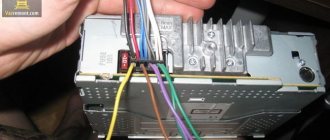
Installation of the HBO control unit
The operation of the equipment is controlled by an electronic control unit, which comes with the 4th generation gas equipment.
Wiring to the control unit.
First you need to decide on the location of the block. Access to it should be free, but at the same time it is necessary to minimize the length of the wiring so that after connecting it, a heap of tangled wires does not form under the hood.
All wiring coming from the controller is divided into several parts, each of which performs its own functions.
The main thing is to have on hand a diagram with a color definition of which part this or that wire belongs to. Or at least this one.
Before connecting the wiring, you need to disconnect the on-board network from the battery.
First, you need to determine which wires are responsible for powering the unit. There should be three of them - to the positive terminal, to ground, and to the positive terminal of the ignition switch. Having separated them, it is better to immediately connect.
Wiring to injectors.
Next, we move on to the wiring responsible for the operation of the injectors - the fuel part. This wiring is connected to the wires going to the gasoline injectors.
After determining which wires are connected to each specific injector, they are inserted.
The color scheme determines which wire needs to be connected to which one, then the connection is made.
You can use conventional twisting followed by insulation, but such a connection is not reliable; it is still better to solder the wires from the control unit at the connection points and then insulate them.
For the fuel part of the wiring, all that remains is to connect the connectors back to the gasoline injectors, and also connect the connectors of the electromagnetic gas injectors.
The fuel part of the wiring is finished, let's move on to the next one.
Signal wiring.
Let's move on to connecting the next part of the wiring - the signal one.
This wiring is designed to transmit signals from sensors that come with the equipment - gas temperature and pressure.
The accompanying instructions indicate in which places the sensors should be placed. After installing the sensors, wiring from the control unit is connected to them.
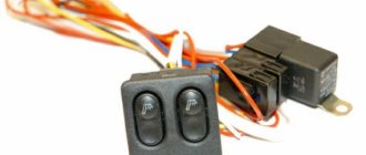
Wiring for the operating mode switching unit.
The last part is the control of the operation of the control unit, that is, the unit for switching the operation of gas equipment.
The control unit is installed in the cabin, in a place accessible for viewing and control.
After which it is wired and connected.
It is advisable to collect all wires into bundles and secure them to prevent the possibility of accidental damage.
The control unit has one more output for connecting a computer, which regulates the operation of the equipment.
This outlet must be freely accessible to facilitate adjustment and diagnostic work.
At this point, the work on installing 4th generation gas equipment on the car is completed.
But what remains is checking the tightness of the system, and then checking and adjusting the operation of the equipment.
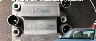
Multivalves Lovato
Lovato 4th generation for those who value quality and save money
The modern line of multivalves consists of two classes:
- Euro class (type 305);
- Class 00 (type 318).
Euro class (type 305) is the multivalve that should be on the gas cylinder of your car. This class of Lovato multivalves is equipped with all necessary (according to the requirements of the Technical Regulations of the Customs Union) safety elements and service functions:
- Technology of filling no more than 80% of the cylinder volume (reserve for thermal expansion of propane);
- An electromagnetic valve that blocks the flow of gas when driving on gasoline, while stopping the engine, or turning off the car's power;
- Fire damper;
- Overpressure relief valve;
- Gas level sensor in the cylinder;
- Manual valve for shutting off the gas flow;
- Emergency valve for gas line break.
In the line of Euro-class Lovato multivalves, you can easily find a device specifically for your gas cylinder, and it does not matter whether it is cylindrical or toroidal, whether it has an external or internal neck (what types of gas cylinders there are are described here). Class 00 (type 318) is a simplified version that lacks some devices: solenoid valve, fire damper. Class 00 (type 318) is a simplified version that lacks some devices: solenoid valve, fire damper
Class 00 (type 318) is a simplified version that lacks some devices: solenoid valve, fire damper.
Checking the tightness of the system
So, the equipment is installed, you need to check the tightness of the system.
To do this, you need to go to a gas station and “blow out” the full tank. But at the same time, the gas supply valve to the system must be closed.
Then he goes to the viewing hole.
All connections and pipelines of gas equipment up to the gas train must be moistened with a soap solution before opening the supply. If gas passes through, this solution will bubble at the leak site.
The leak test can be done in parts. First, moisten the pipes coming from the cylinder with the solution.
Not only the connections are checked, but also the pipelines themselves, since a leak can occur due to a defect in the pipeline itself or in the event of a breakdown during installation.
After checking the lines going into the engine compartment, you need to check the tightness of the connections of the equipment installed there.
The gas supply to the reducer and the outlet from it to the gas train are checked. There is no need to check further until the equipment is connected to operation.
Connections downstream of the gas train can be checked later.
If the tightness test shows that there is no gas passage, you can proceed to the next step. If a leak is detected, for example, at the junction of pipelines with equipment, then the gas supply is shut off and additional crimping or repacking of the connection is performed. After which a re-check is carried out.
If a leak is found in the pipeline itself, it must be replaced from connection to connection.
Attempting to seal a leak with improvised means practically does not lead to positive results.
After replacing the damaged pipeline, a leak test is carried out again. It is important to ensure that there are no gas leaks anywhere.
Connecting HBO to PC
Both the cord and the diagnostic program can be purchased. Typically, equipment manufacturers sell them.
After installing the software on the laptop, it is connected to the control unit.
In order for their connection to occur, the control unit must be powered, that is, the ignition switch must be turned on, but the engine must not be started.
If the connection does not occur, the laptop may have an outdated version of software installed, but you also need to check the tightness of the contacts.
If the connection is successful and the program is launched, all the basic information on the engine will be displayed on the laptop monitor - the number of cylinders, types of installed injectors, their polarity, engine speed, current temperature, pressure in the system.
In this case, the system control unit installed in the cabin should light up with warning lights.
One is green, indicating the use of gasoline as fuel, and will glow constantly, the second, red, will flash, signaling the possibility of connecting gas equipment to operation.
In the future, if the equipment is properly configured, signals will be sent to this unit in accordance with certain operating modes.
Basic parameters of injectors
The development of gas cylinder equipment has provoked the emergence of a huge number of varieties of nozzles. The parameters for the division of dispensers are not several positions, but about ten of the most important divisions. To be more precise, HBO injectors are classified according to:
- Case material (metal or plastic);
- Type of fuel being dosed (propane-butane or methane);
- Coil operating voltage;
- Working pressure and maximum possible;
- Opening and closing times (that is, they can be instantaneous, delayed or customized);
- Electrical resistance of the coil;
- Operating temperature range;
- The outer diameter of the outlet fitting;
- Valve seat diameter;
- Jets available for calibration.
In fact, most of the characteristics of LPG injectors are not required by the average car enthusiast when selecting them. However, for experienced motorists or mechanical aces, each parameter can be extremely important, because the totality of them largely determines the nature of the functioning of a gas engine.
Auto-configuration of equipment
In this case, you need to press the button for forced operation on gasoline. After this, the red warning light will go out.
To configure the operation of gas equipment, the power plant must be warmed up on gasoline.
After starting the engine, the correct compatibility of the program with the control unit can be checked again by comparing the indicators of the on-board computer with the indicators on the laptop screen, since information about the operation of the engine is displayed there.
After the engine reaches the optimal operating temperature, you can begin auto-calibrating the operation of gas equipment.
This is done by clicking on the window that says “auto-tuning” on the laptop screen.
The essence of this setting comes down to the following. After turning on auto-calibration, the electronic control unit checks the main parameters of the engine - operating temperature, pressure, etc., and, if they correspond to the required parameters for calibration, begins to connect one of the gas injectors to operation.
To do this, he turns off the working injector and connects the gas one; he usually starts doing this from the first cylinder; the connection of the gas injector can be monitored on the laptop monitor.
But when connected, the control unit supplies minimal fuel, which leads to engine vibration, since the control unit has not yet adjusted to the operation of the standard control unit.
Next, the control unit begins to receive information from the standard unit and process it, that is, adapt to its operation; as a result, it adjusts the amount of gas, which is equivalent in energy output to the amount of gasoline. With the correct amount selected, the vibration of the power plant will subside.
Next, the control unit performs the same operation, but with a different nozzle.
Moreover, the control unit for calibration uses the non-sequence of the arrangement of the cylinders, but the order of their operation. If, for example, the operating order is 1-3-2-4, then he will calibrate the injector of the third cylinder next.
Since the sequence of actions of the control unit is identical to the first cylinder, when the gas injector of the third cylinder is connected to operation, the vibration of the power plant will appear again, but it will be weaker.
Next, when calibrating the remaining injectors, you can determine whether the gas equipment was connected completely correctly.
The fact is that after connecting the second gas injector to operation, if installed correctly, the activation of the remaining injectors will not manifest itself in the form of vibration of the power unit, since the supply of gas to two injectors and one gasoline during calibration is sufficient for the engine to operate without vibration.
If vibration persists even after calibrating the second injector, this is a signal that the correct gas supply to one of the electromagnetic injectors has been disrupted.
Problems with operation can be caused either by the difference in the length of the pipes from the ramp to the fittings or by a leaky fitting of the fitting.
The program installed on the laptop will indicate on which cylinder the malfunction occurred. If this malfunction occurs, it must be corrected. Next, auto-calibration is performed again.
Setting up HBO yourself
Let us immediately note that if installing an LPG taking into account the instructions is a complex but feasible task, setting up an LPG assumes that there is a clear understanding of why this or that action is being performed. In other words, for example, setting up a 4th generation Digitronic HBO with your own hands or setting up any other system can rightfully be considered a complex and responsible task.
It is important to understand that errors in settings can lead to unstable operation of the internal combustion engine, various failures, and even failure of the power plant and individual vehicle systems. Please note that if you are not confident in your abilities, it is better to immediately entrust this procedure to an experienced master. If you want to configure the HBO yourself, you will need to buy a special wire (cable) and also install the appropriate software on your laptop.
Please note that the information below is general, that is, it allows you to configure the gas system “on average” so that the engine runs on gas, without the risk of breaking the internal combustion engine or reducing its service life. However, only a specialist can make fine adjustments, which reduces consumption in different modes, increases engine performance on gas, etc.
We also recommend reading the article about whether gas is harmful to a car engine. From this article you will learn about the effect gas has on the engine, as well as how much the engine life is reduced after installing gas equipment, which affects the durability of the engine when running on gas, etc.
By the way, all systems are similar to each other, that is, for example, setting up a 4th generation Lovato LPG with your own hands will not differ much from similar settings in other systems. The only difference is in the graphical interface of the programs themselves and some options that are needed for advanced configuration.
- So, before starting the setup, you need to warm up the car until the engine reaches operating temperatures. Next, you need to remove all load from the internal combustion engine, except for idling (turn off the heater, headlights, dimensions, additional equipment, etc.). Now you can connect with a cable and run the unit setup program. Let's look at the HBO tincture, using the STAG4 program as an example.
First, in the program window, you need to set the number of engine cylinders per coil; the RPM speed must also match the engine speed (550-940). All data must exactly match the vehicle.
After this, you need to go to the tab where the switch-on temperature is set. For summer not lower than +35, and for winter not less than +40. Cylinder shutdown is set to 250. This will allow for a smooth transition from gasoline to gas and back, without engine vibration.
As for pressure error time, this parameter is set at 300 to 420. When choosing the type of gas injectors, it is important that the selected type is exactly the same as those on the machine. If the owner does not know which injectors are installed, the injectors need to be inspected. Manufacturers usually mark them so that the program can then determine which injectors are installed.
The operating pressure of the gearbox should be from 1.0 to 1.3 bar, the minimum is not less than 0.50. Fuel type LPG for propane or CNG for methane (marked). Now you can go to the automatic configuration tab and click start (start). All you have to do is wait from 1 minute to 5 minutes. The setup time depends on how well the car runs on gasoline. If the engine is not running stably, there are problems with the ignition system, etc., then it will take more time for auto-tuning.
Next you need to go to the map tab. There you can see that the orange line has taken a bend. So, it is important to note from which number in the coefficient section the line begins. It is good if the line lies in the range of numbers from 1 to 1.4. The fact is that when installing LPG, a specialist must select the right injectors in terms of performance, taking into account the power of the car’s engine.
The fact is that some injectors can be adjusted to the engine, since they have a performance margin, while others are designed for a specific power and the margin is minimal. In any case, the pressure of the reducer is important for all types of injectors. During auto-tuning, the program itself will calibrate the pressure of the reducer, and the line may become higher than a coefficient from 1 to 1.4 or lower than this indicator.
In the first case, overestimation indicates that the pressure is from 1 to 1.3 bar, but the injector nozzles are too narrow. This suggests that it is possible to increase the performance of the injectors by drilling out the nozzles and making them wider, which will increase the throughput.
If the line is below the coefficient, this indicates large nozzles. In this case, the throughput of the nozzles is reduced by changing the nozzles to suitable analogues with a smaller diameter. Note that the line at a pressure of 1-1.3 should normally be in the range of the coefficient 1-1.4. With such indicators, throttle response is maintained, gas consumption does not exceed 20% compared to gasoline, and the engine operates under normal conditions, there is no big risk of reducing its service life.